Security systems CP155B How to use

CP155B
Weather Resistant Keypad With Prox
Security System
Installer Reference Guide
EN
Security Systems

CP155B Installer Reference Guide
2Bosch Security Systems 02/18 CP155BIRG FTR1.2
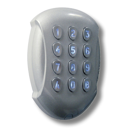
The CP155B keypad provides alarm and or access control
functionality when used on selected Solution security
control panels. It is fitted with built in smart prox reader,
front and read tamper. Constructed from high strength
UV resistant plastic, the CP155B keypad provides a high
level of durability and is also weather resistant to IP65
making it ideal for external installations.
The CP155B includes red, green and blue indicators
which are used to show area or door lock status. Buttons
with backlit make it easy to operate in all lighting condi-
tions.
The keypad connects to the control panel via the RS485
encrypted LAN and occupies a standard keypad position
in the panel configuration.
CP155B Keypad Compatibility
Panels Supported Version Keypads Supported
Solution 6000 2.25 Up to 16
Table 1: CP155B Compatibility
Various keypad options can be configured via the De-
vices - Keypad & Readers menu in panel programming.
User access events are stored in the panel log and can
also be reported if required.
Keypad Addressing
Each keypad fitted to the system must be assigned a
unique address on the LAN. The CP155B includes a DIP
switch for quick address selection. The following table
shows the address setting for each keypad as well as the
number of keypad devices each panels can support.
Keypad Address Setting
Address Switch On
Solution 6000 Panel
1
2 1
3 2
4 1 2
5 3
6 1 3
7 2 3
8 1 2 3
9 4
10 1 4
11 2 4
12 1 2 4
13 3 4
14 1 3 4
15 2 3 4
16 1 2 3 4
Table 2: Keypad Address
CP155B - Weather Resistant Keypad With Prox
DIP Switch 5
LAN Termination if required can be enabled by
placing dip switch 5 in the ON position.
1
ON
2345
Figure1: Keypad Address Switch
i
Note
Only 1 Keypad can be assigned to each address.
All keypads are supplied from the factory set to
address 1. You must power cycle the panel or
perform a LAN scan whenever you change the
keypad address.
Box Contents
The CP155B box contains the following parts.
Keypad and Mounting Plate
Plug On Connection Cable and Grommet
Instruction Sheet
Address Switch Plug
1x Proximity Card
2 x (M3 x 6mm) Hex Screws
1 x 2mm Hex Key
Installation
The keypad should be installed onto a solid surface us-
ing suitable mounting fixtures. Wiring should only be
performed while the control panel is powered down.
Step 1) Mark out the location of the mounting holes
and the cable exit hole before drilling out all
points as necessary. Secure the mounting plate
with approproate fasteners.
Step 2) If the rear tamper is required, fit the tamper
screw securely through the backplate to the
wall.
Step 3) Use the connection diagram [Figure 6] to ter-
minate the supplied cable as required. Unused
wires should be insulated to prevent short
circuits.
Step 4) Remove the address grommet to expose the DIP
switch and set the required address using [table
2] Be sure to refit the address grommet securely
before assembling and mounting the keypad.
Note Each keypad on the system must have a
unique address.

CP155B Installer Reference Guide
3
Bosch Security Systems 02/18 CP155BIRG FTR1.2
Keypad Operation
The CP155B keypad can be configured to provide sys-
tem area control, door access control or both depending
on the installation requirements.
As there is no LCD display on the keypad, feedback is
provided via the red, green, blue LED’s and the keypad
sounder.
The CP155B also includes an egress input and lock out-
put which can be used to control door access if required.
i
Note
Using the on board lock output is not recommend-
ed when the CP155B is being used on an external
wall of the building. In this case it is recommended
that you run the lock control wires directly to an
output located on the main panel or output ex-
pander module located inside the building.
Keypad Button Functions
The CP155B keypad consists of 13 individual buttons
which are used to enter PIN and control the system.
Some buttons have a secondary functions that are acti-
vated by holding the button down for two seconds.
The [#] and [*] buttons perform the same functions as
the ON and OFF buttons on the standard display keypad.
#Button = ON Button
*Button = OFF Button
Keypad Button Functions
Button Description
[0] to [9]
The numeric buttons allow you
to enter PIN numbers and other
functions when required.
[#]
To arm the system enter the user
PIN followed by the [#] key.
The [#] key performs the same
function as the ON button on
display enabled keypads.
[*]
To disarm the system enter the
user PIN followed by the [*] key.
The [*] key performs the same
function as the OFF button on
display enabled keypads.
[ ] TBA
Table 3: Button Functions
Step 5) Attach the connection cable to the keypad by
plugging in the connector. Note the connector
is polarised and will only plug in when correctly
aligned. Do not use excessive force.
Step 6) Fit the cable grommet in place by pressing the
first flange into the hole and leaving the second
flange on the outside of the keypad. Make sure
it sits nealy in all places to insure a correct water
resistant seal.
Step 7) Carefully hook the keypad to the backplate and
fit the 2 Hex screws using the allen key supplied.
See figure 4-5.
Figure 5: Keypad Mounting
angle
Tamper
Screw
Spirit
Level
Mounting
Holes
Cable
Entry
Figure 3: Assembly Side On
Figure 4: Screw In Base To
Mounting Plate.
Figure 2: Mounting Bracket

CP155B Installer Reference Guide
4Bosch Security Systems 02/18 CP155BIRG FTR1.2
LED Operation For Area Control
Led Condition Meaning
Red
On Area All On
Flashing Area Alarm
Green
On Area is OFF
Flashing Area not ready to turn on -
zone(s) unsealed
Red &
Green Both On Area armed in Part mode
and all zones sealed.
Red &
Green
Red On
and Green
Flashing
Area armed in Part mode
with zones unsealed.
Red &
Green
Alternate
Flashing
Keypad initialising during
power up or LAN scan.
Red &
Green Both Off
Home Area and Door As-
signment not programmed
or keypad not powered.
Table 5: Keypad LED’s - Area Control
To have the keypad control an area on the alarm system
you need to assign the keypad to a home area. See the
Devices-Keypads-Home Area menu option in panel pro-
gramming. If alarm system control is not required then
you should set the home area option to No Area.
To have the keypad control a door on the system you
will need to assign a door to the keypad. See the De-
vices-Keypads-Door Assignment menu option in panel
programming.
LED Function For Door Control
Led Condition Meaning
Blue On Door Locked
Blue Fast Flash Door Unlocked
Blue Continuous
Fast Flash
Door manually unlocked
or overridden.
Blue 2 Flashes Door automatically un-
locked by time zone
Red &
Green
Alternate
Flashing
Keypad initialising during
power up or LAN scan.
Blue Off Door not programmed or
keypad not powered.
Table 6: Keypad LED‘s - Door Control
Hold Down Functions
The CP155B keypad supports the following hold down
functions. These functions will only work if the keypad
has been assigned to an area. When keypads are in-
stalled outside the premises and are being used for area
control, it is recommended that you disable the emer-
gency key functions to prevent nuisance alarms.
See the Devices-Keypads & Readers-Emergency Keys
menu option in panel programming to disable these
features.
Hold Down Functions
Function Meaning
Panic
Alarm
Press and hold both the [1] and [3]
keys down for 2 seconds to initiate
a panic alarm.
Fire
Alarm
Press and hold both the [4] and [6]
keys down for 2 seconds to initiate
a fire alarm.
Medical
Alarm
Press and hold both the [7] and [9]
keys down for 2 seconds to initiate
a medical alarm.
All ON
Enter a valid PIN and then press
and hold down the [#] key, the
system will turn On or Arm all areas
that the user belongs to at the
same time.
All OFF
Enter a valid PIN and then press
and hold down the [*] key, the
system will turn Off or Disarm all
areas that the user belongs to at
the same time.
Table 4: Hold Down Functions
i
Note
The hold down 4 - Chime Mode and hold down
6 - Answer Incoming Call features are not currently
supported from the CP155B keypad.
Keypad LED Indicators
The CP155B keypad includes RED and GREEN indica-
tor LEDs which provide visual feedback during system
operation.
The Red & Green indicators will show alarm &/or area
status. The Blue indicator will show door status.
i
Note
The keypad can display alarm and door status at
the same time.

CP155B Installer Reference Guide
5
Bosch Security Systems 02/18 CP155BIRG FTR1.2
Once assigned to a door, the on-board Lock output and
Egress input will automatically be assigned to the same
door as the keypad.
If both alarm area and door control is required then
you will need to assign a home area and a door to the
keypad.
i
Note
The CP155B LED indicators will only display the
status of the programmed home area. You can-
not move between areas from this keypad. If you
require multiple area status visibility you should use
a display keypad like the CP700B.
Keypad Alert Tones
The CP155B keypad emits several distinct tones to alert
you to particular system events. The keypad volume lev-
el cannot be adjusted on the CP155B however it can be
turned off via panel programming by setting the keypad
volume to the lowest level. See Devices-Commands-
Volume menu in panel programming.
i
Note
Setting the keypad volume to off will also stop the
key press beep during normal operation.
Keypad Alert Tones
Event Alert Tone Emitted
Fire
Alarm
If the system registers a fire alarm, the
reader will sound 3 short beeps fol-
lowed by a 1.5 second pause. This will
repeat until reset by the user or until
the siren run time expires.
Burglary
Alarm
If the system registers a burglary
alarm, the keypad will sound a con-
tinuous siren tone until reset by a user
or until the siren run time expires.
Trouble
If a system trouble condition occurs,
the keypad will sound 4 x fast short
beeps followed by a 5 second pause
and will repeat this tone until the user
acknowledges the trouble
condition from a display keypad
Key
Press
The keypad will sound one short beep
every time a button is pressed.
Exit
Delay
The exit delay warning will sound 1
short beep every second when the
area the keypad has been assigned to
is armed. During the last 10
seconds of exit time the warning tone
will speed up indicating that the time
has nearly expired.
Entry
Delay
The hi/lo entry delay warning tone will
sound once every second when an en-
try delay zone in the area the keypad
has been assigned to is triggered. If
the system is not disarmed before the
entry time expires then an alarm will
occur.
Error
If you press an invalid button during
any data entry sequence, the keypad
will sound a 2 second warning tone
indicating that the command was not
accepted.
Chime
Alert
If chime mode is active then the
keypad will sound fast short beeps
to alert the user when a zone pro-
grammed for chime is opened. Chime
mode is only applicable when the area
is disarmed.
Table 7: Keypad Tones
i
Note
When keypads are installed outside the premises,
you may prefer that the alert tones are disabled.
See the Devices-Keypads & Readers-Indicator Op-
tions menu in panel programming to disable these
features.
Egress and Lock Control
The CP155B includes a lock output and egress input
which can be used to simplify the wiring when the
keypad is being used for access control. The lock output
consists of a Form 1c Relay capable of handling 2Amps
@ 24v DC which can drive a door lock or trigger a third
party device like a gate controller. The output is a clean
change over relay contact that is electrically isolated and
will operate for a fixed 5 seconds whenever the associ-
ated door is operated
i
Note
The on board lock output will operate for a fixed
time period of 5 seconds when triggered. If a dif-
ferent time is required then you should use another
output on the system to operate the door lock.
Depending on the system load, the panel power supply
may not be sufficient to operate the door lock, espe-
cially in cases where it is power to lock and a separate
power supply should be fitted. When operating DC door
strikes the back EMF energy generated when the lock is
released should be shunted with a reverse diode and is
not always provided by the door strike manufacturer.
The Egress input [Green Wire] on the CP155B keypad al-
lows you to simplify the wiring required to implement an
egress button on the inside of the door. The egress input
triggers the lock output on the keypad by operating the
associated door that has been assigned to the keypad.
The egress input should be connected via a momentary

CP155B Installer Reference Guide
6Bosch Security Systems 02/18 CP155BIRG FTR1.2
or push button switch to keypad ground [-]. When the
egress button is pressed the lock output on the keypad
will trigger for a fixed 5 second period. For greater se-
curity, if the egress input is not being used it should be
disabled via panel programming. See Devices-Keypads &
Readers-General Options in panel programming.
i
Note
Any zone on the system can be configured to trigger
a door and can therefore also be used to operate
the lock output on the CP155B.
Configuration Examples
Alarm control function only.
1) Install the keypad as per instructions.
2) Set the home area for the keypad.
3) Set keypad options as required remembering to dis-
able keypad emergency alarms and or single button
arming if the unit is being installed externally.
4) Assign users to the area.
Access control function only.
1) Install the keypad as per instructions.
2) Assign the keypad to a door.
3) Set keypad options as required.
4) Set output to door.
5) Set output event assignment.
6) Assign users to the door.
Both Alarm and Access control functions.
1) Install the keypad as per instructions.
2) Set the home area for the keypad.
3) Assign the keypad to a door.
4) Set keypad options as required remembering to dis-
able keypad emergency alarms and or single button
arming if the unit is being installed externally.
5) Set output to door.
6) Set output event assignment.
7) Assign users to the area.
8) Assign users to the door.
Examples show how to configure the CP155B to control
a door. Consult the control panel installation manual for
further programming information.
Smart Card Credentials
There are a number of compatible token styles available
to suite your customer. The PR370 is a grey token that
incorperates both the EM and Smart Card formats with
identical 40bit credential allowing the one token to be
used accross different technologies.
You may have a site that is running the dated EM for-
mat but now installing a new site with the high security
Smart Card Format and want to use the same tokens
across both sites.
PR301
Smart Card Token
PR350
Smart Card
PR370
Dual Smart Card
Token
PR365
Adhesive Sticker

CP155B Installer Reference Guide
7
Bosch Security Systems 02/18 CP155BIRG FTR1.2
Connection Diagram
SW5=LANTERM
CP155
1 2 3 4 5
ON
1
ON K E
2345
Not Used
EGRESS
INPUT
N/O
BK
RD
WH
BL
YL & GY
GN
RED
BLACK
WHITE
BLUE
= LAN +
= LAN -
= LAN A
= LAN B
BROWN
ORANGE
PURPLE
GREEN
= RELAY NO
= RELAY COM
= RELAY NC
= EGRESS
YELLOW
GREY
= NOT USED
= NOT USED
Control Panel
Wiring Legend
CM720 or CM723
Power Supply
(Battery backed up)
+ -
DOOR
LOCK
Egress
Input
BACK EMF
DIODE
+
MODULE LAN
CONTROL PANEL
-A B
+
E
x
t
e
r
n
a
l
K
e
y
p
a
d
PPL - NC
ORG - COM
BRN - NO
LOCK RELAY
PPL - NC
Door Control
Not Used
CP155B Specifications
Part Number: CP155B - External Keypad Weather Resistant With Smart Prox.
Operating Voltage: 10.0V D.C. - 14.5V D.C. @ 100mA Max.
Module Connection:
(RS485 LAN)
Max total LAN length using multi strand security cable = 500m.
Max total LAN length using 2 pair twisted shielded data cable (Belden 8723) = 1200m.
See the control panel manual for complete wiring instructions.
Lock Output: Relay form 1c, 24v DC at 2Amp
Egress Input: Low to trigger. Can be disabled via software control.
Format: 2 way 13.mhz High Security Encrypted smart Card
Compatable Smart Prox Cards: PR301, PR365, PR370, PR350
Dimensions: 83mm(W), 30mm(D), 129mm(H)
Environment: -10˚ to 55˚C RH 5 to 93% non-condensing IP65.
Fixing Method: The CP155B should be mounted on a sturdy vertical wall using fixtures appropriate for the wall
construction type.
Warranty: 3 years from date of manufacture (return to base).
N12138N12138 RoHS
In the interest of ongoing product development this
document is subject to change without notice.
Figure 6: CP155B Connection Diagram
The egress input is low (0V) to
trigger. The input should be
disabled via panel program-
ming if not being used.
Keypad connection point.
Only use the supplied cable to
connect to this keypad.
Address Select Switch. Keypads must be
set to a unique address as per“Table 2:
Keypad Address” on page 2.
All CP155B keypads are supplied from
the factory set to Address 1.
You must power circle the panel or
preform a LAN scan after connecting the
CP155B for the system to initialise the
keypad.
i
Note
CP155B Firmware
must be 2.01 or later.

Bosch Security Systems
Level 2, 21 Solent Circuit
Baulkham Hills, NSW 2153
Australia
Phone: 1300 026 724
www.boschsecurity.com.au
© 2018 Bosch Security Systems
CP155BIRG
Issue FTR1.2
Table of contents
