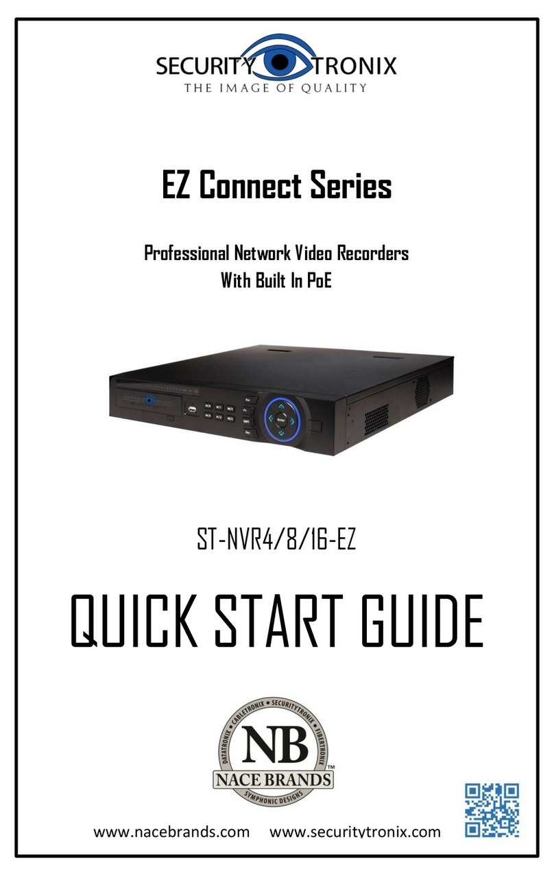
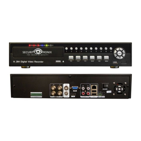
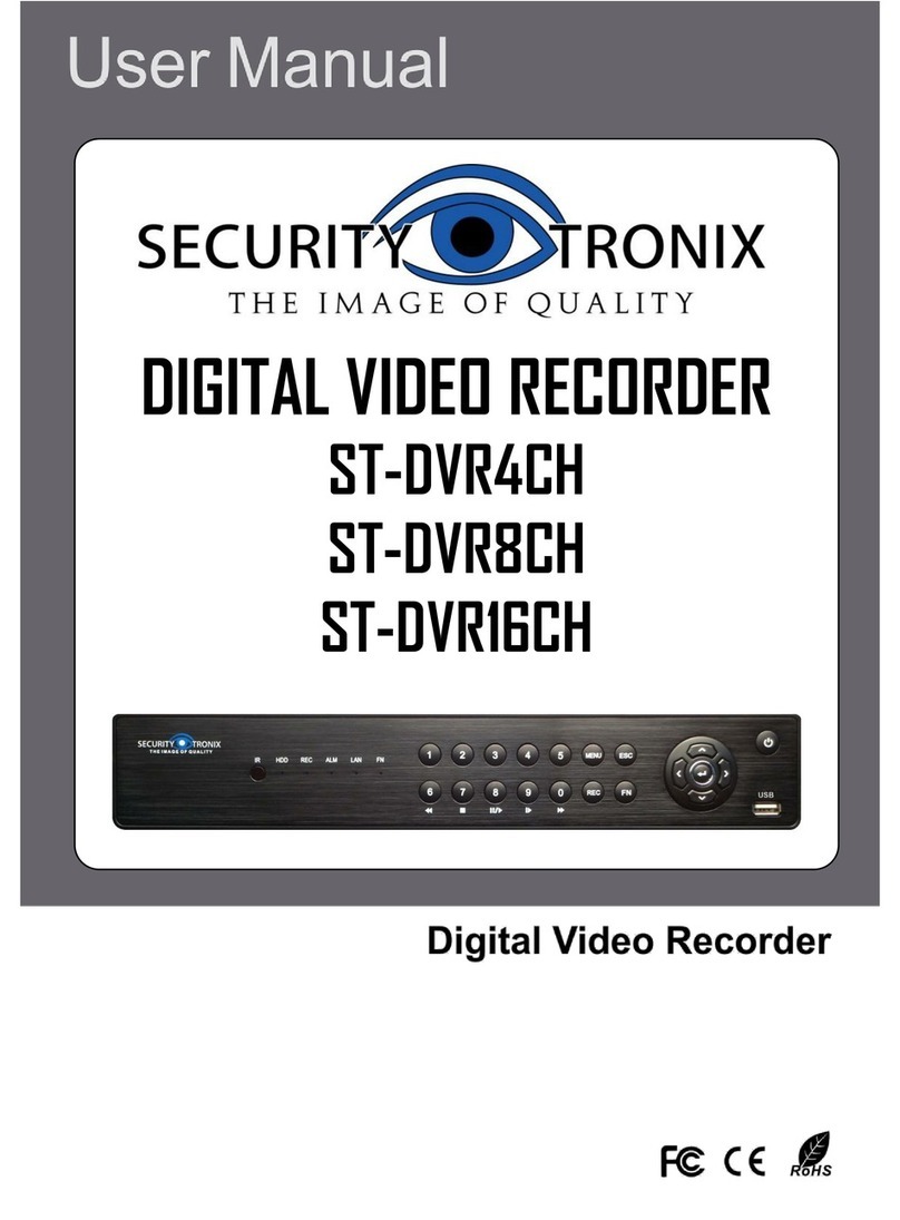
Securitytronix ST-DVR7204G User manual

v2.0 11/8/11
1
USER MANUAL
ST-DVR7204G
4-Channel Digital Video Recorder

v2.0 11/8/11
2
TABLE OF CONTENTS
PACKAGE'CONTENTS....................................................................................................4!
PRODUCT'DESCRIPTION ...............................................................................................4!
SPECIFICATIONS ...........................................................................................................5!
INSTALLATION .............................................................................................................6!
1.!UNPACKING and HANDLING ................................................................................................................. 6!
2.!MECHANICAL INSPECTION ................................................................................................................... 6!
3.!SPECIAL ATTENTION................................................................................................................................. 6!
4.!WIRING CONNECTIONS and HARD DRIVE INSTALLATION.............................................. 7!
5.!HARD DRIVE (HDD) INSTALLATION................................................................................................. 8!
HDD Storage Calculator ......................................................................................................................................8!
CONTROLS .................................................................................................................10!
1.!FRONT PANEL CONTROLS................................................................................................................. 10!
2.!INFRARED REMOTE ................................................................................................................................ 11!
3.!MOUSE CONTROL .................................................................................................................................... 12!
Left Mouse Key –Single Click ...................................................................................................................... 12!
Right Mouse Key –Single Click ................................................................................................................... 12!
OPERATION ...............................................................................................................13!
1.!POWERING ON and SHUTTING DOWN....................................................................................... 13!
Powering On ............................................................................................................................................................ 13!
Shutting Down......................................................................................................................................................... 13!
2.!ACCESSING SYSTEM MENU ............................................................................................................. 14!
3.!USER ACCESS RIGHTS ........................................................................................................................ 14!
4.!PREVIEW MODE......................................................................................................................................... 15!
5.!MAIN MENU ................................................................................................................................................... 15!
6.!RECORDING OPERATION ................................................................................................................... 17!
Manual Recording ................................................................................................................................................ 17!
Auto Recording....................................................................................................................................................... 18!
Auto Recording –Motion Detection Recording................................................................................... 19!
Auto Recording –Video Blind........................................................................................................................ 22!
Auto Recording –Video Loss ........................................................................................................................ 23!
7.!PLAYBACK OPERATION ....................................................................................................................... 24!
8.!BACKING UP RECORDING FILES................................................................................................... 27!
File Backup –PlayBack/File Search Screen ........................................................................................ 27!
File Backup –Direct From Main Menu..................................................................................................... 28!
9.!PTZ CONTROL............................................................................................................................................. 29!
PTZ Camera Connection.................................................................................................................................. 29!
PTZ Camera Configuration ............................................................................................................................. 30!
PTZ Camera Control........................................................................................................................................... 31!
Setting Presets ....................................................................................................................................................... 31!
Tour Between Points........................................................................................................................................... 33!
Pattern......................................................................................................................................................................... 34!
Border Scan ............................................................................................................................................................. 35!
Auto Pan, Flip and Reset .................................................................................................................................37!
Other PTZ Control Functions......................................................................................................................... 37!
v2.0 11/8/11
3
10.!SYSTEM SETTINGS............................................................................................................................... 38!
General Settings.................................................................................................................................................... 38!
Encode Settings..................................................................................................................................................... 40!
Network Settings ................................................................................................................................................... 40!
Network Service Settings.................................................................................................................................42!
GUI Display Settings........................................................................................................................................... 47!
PTZ Configuration Settings............................................................................................................................. 48!
Display Tour (Screen Sequencing) Settings......................................................................................... 48!
11.!ADVANCED FEATURES ...................................................................................................................... 49!
HDD Management................................................................................................................................................ 49!
User Account Management ............................................................................................................................ 50!
Online User............................................................................................................................................................... 52!
Output Adjust........................................................................................................................................................... 52!
Auto Maintain .......................................................................................................................................................... 53!
Restore Defaults.................................................................................................................................................... 53!
Upgrade...................................................................................................................................................................... 54!
Device Information ............................................................................................................................................... 55!
12.!SYSTEM INFORMATION..................................................................................................................... 55!
Hard Disk Information......................................................................................................................................... 55!
BPS Code Stream Statistics........................................................................................................................... 56!
Log Information ...................................................................................................................................................... 56!
Version Information.............................................................................................................................................. 57!
13.!MISCELLANEOUS FUNCTIONS and SETTINGS.................................................................. 58!
Disk Event .................................................................................................................................................................58!
Color Settings.......................................................................................................................................................... 58!
REMOTE'MANAGEMENT'USING'CLIENT'SOFTWARE ...................................................60!
1.!CMS SOFTWARE INSTALLATION ................................................................................................... 60!
CONFIGURING and USING THE CMS CLIENT ............................................................................... 62!
2.!SNS SOFTWARE INSTALLATION .................................................................................................... 74!
CONFIGURING and USING THE SNS CLIENT................................................................................ 76!

v2.0 11/8/11
4
PACKAGE CONTENTS
This package contains:
One ST-DVR7204G 4-channel digital video recorder
One infrared remote control with 2 AAAbatteries
One optical mouse
Two hard drive cables (inside the unit)
Eight hard drive screws
One power supply
One user manual
One CD with manufacturer documentation and remote management software
PRODUCT DESCRIPTION
The ST-DVR7204G is a cost-effective DVR designed for the security professional as a digital
surveillance product. Based on an embedded LINUX operating system the ST-DVR7204G
provides a very stable platform featuring standard H.264mp video compression and G.711A audio
compression to ensure high quality imaging, low error coding ratio and single frame playback. With
TCP/IP protocols this DVR offers remote network communications, surveillance and management
capabilities. The ST-DVR7204G can be deployed standalone or on a network and integrated into a
complete security surveillance network in residences, offices, banks, warehouses, factories,
prisons or any environment requiring surveillance monitoring.
Important Notes
The DVR’s embedded PTZ controller is designed to perform a wide variety of PTZ camera
control functions. However, the utility of any PTZ controller is highly dependant upon the
particular PTZ camera to be controlled as each camera has not only its own functions,but
specific methods of how those native functions are accessed and managed. Further, a
particular PTZ controller’s terminology may differ from that used by a particular PTZ
camera. Therefore, it will be necessary for the installer and/or user to consult BOTH the
DVR manual and PTZ camera’s user manual to ensure proper set-up, configuration and
application.
Securitytronix DVRs are capable of various levels of video quality as set by the user. It is
solely the user’s responsibility to determine the required video quality level during set up.
Should the user believe they will ever need the video quality to be used for evidentiary
purposes, then they should consult with their legal advisor to determine the video quality
level to set the DVR to.

v2.0 11/8/11
5
SPECIFICATIONS
ST-DVR7204G
Specifications (Typical)
1. Compression
H.264
2. Video Signal
NTSC
3. Video Input
4 BNC Female
4. Video Output
1 VGA, 1 BNC
5. Audio Input
1 RCA Female
6 Audio Output
1 RCA Female
7. Record
D1, HD1, CIF, QCIF
8. Recording Modes
Manual, Motion Detect, Schedule
9. Local Playback
25fps for CIF, 12fps for HD1, 6fps for D1
10. Playback Options
Single or Multiple Channels
11. Record Search
Time Search, Calendar Search, Event Search, Channel Search
12. Display FPS
D1: 120fps (NTSC)
13. Record FPS
CIF:120fps, HD1: 120fps, D1: 120fps NTSC
14. Storage
2 pcs (SATA) HDD up to 2TB
15. Backup
Network and USB
16. HDD Capability/Channel
Audio: 28.8Mbytes/hr, Video: 25-450Mbytes/hr
17. Controller
Front Panel Buttons, Remote Controller, USB, Web
18. Operating System
Linux
19. Image Display
Full Screen, 4 Split
20. Network Port
RJ45 10M/100M Adaptive Ethernet Network Port
21. PTZ Control Port
1 RS485
22. USB Port
2 USB Ports
23. Web
DDNS, TCP/IP, PPPoE, IE, & Client Software
24. Operating Temperature
32°F -130°F
25. Operating Humidity
10% -90%
26. Dimensions
13” W x 10.5” D x 2 .8” H
27. Weight
3.3 lbs (without hard drive)
28. Power
DC12V @3.3A

v2.0 11/8/11
6
INSTALLATION
CAUTION: To reduce the risk of electrical shock, only remove the cover after
disconnecting all power to the unit and only to install/remove the hard disk drive. There
are no user serviceable parts inside the unit.
CAUTION: To prevent electric shocks and risk of fire hazards, do not use other than
specified power source.
This DVR has been designed for indoor use only. Outdoor use voids warranty and poses
serious electrical and fire hazard risks to the installer, user and facility.
1. UNPACKING and HANDLING
Each unit is shipped assembled and factory tested.
Ensure that all accessories are removed from the container before discarding packing material
2. MECHANICAL INSPECTION
Inspect the front and rear of the equipment for shipping damage. Make sure the equipment is
clean, and no connectors are broken, damaged, or loose. If equipment appears to be
damaged or defective please contact your distributor or Securitytronix at 1-610-429-1511 for
assistance.
3. SPECIAL ATTENTION
a. The installer must comply with electrical safety standards.
b. This DVR is for indoor use only and must be installed in a safe, ventilated and dry area.
c. Open the DVR case only to install the hard drive(s). There are no serviceable parts inside
the unit.
d. If liquids spill inside the DVR’s case immediately turn off all power to the unit, disconnect
the unit from its power source and have a qualified technician check it for damage.
e. Do not install the DVR in an environment where the temperature is above 104°F.
f. Only use a dry cloth to clean the unit. If there is dirt that is difficult to remove wipe gently
with a mild detergent. Never use strong or abrasive detergents.
g. A minimum 12VDC 5A power supply must be used. AC power cannot be applied. Using
an AC or other incorrect power supply will damage the unit.
h. Only qualified installers are allowed to install, test and disassemble the DVR.
i. As the DVR is a sensitive device any shock or other shaking of the unit will cause damage
and void the warranty.
This symbol is intended to alert the user to the presence of important operating and
maintenance (servicing) instructions.
This symbol is intended to alert the user to the presence of uninsulated “dangerous
voltage” within the product’s enclosure that may be of sufficient magnitude to constitute a
risk of electrical shock.

v2.0 11/8/11
7
4. WIRING CONNECTIONS and HARD DRIVE INSTALLATION
Item
Panel Key/Indicator
Description
1
1CH, 2CH, 3CH, 4CH
Video In BNC ports for cameras 1 through 4
2
V-OUT
Video Out BNC port for connection to a monitor
3
A-IN
Audio In RCA port
4
A-OUT
Audio Out RCA port
5
NET
Ethernet jack for connection to a local area network (LAN)
6
USB
USB ports for the optical mouse and back up drive/flash drive
7
AB 485
RS485 connections for controlling a PTZ camera
8
DC 12V
Port for connecting the included 12VDC power supply
a. Using a quality 75 ohm coaxial cable with a BNC connector,connect the camera(s) to the
DVR’s CAM In port(s).
b. Using a quality 75 ohm coax cable with a BNC connector,connect the video monitor to the
DVR’s MON Out port. If the display is a VGA monitor then connect the monitor’s VGA
cable to the DVR’s VGA port.
c. If audio monitoring is required,connect the audio monitoring device to the DVR’s RCA A-
OUT port.
d. To control a PTZ camera using the DRV’s embedded PTZ controller use the DVR’s
RS485 A and B connections. A is positive (+), B is negative (-). Be sure the polarities are
correct and consistent with the camera. You may also use the RS485 AB connections for
an external PTZ controller.
e. If the DVR is to be networked for remote monitoring and/or management connect the unit
to the network using the Ethernet jack.
f. USB ports –The DVR has 2 USB portslocated on the back of the unit. One port is
intended for the optical mouse. The second USB port is can be used for backing up files to
a separate drive (e.g., flash drive, CD/DVD burner, etc.).
g. Hard Drive Installation – Unless ordered with and preconfigured at the factory, the DVR
requires a DVR hard drive to be installed. This unit will support a single hard drive up to
2TB. Secure the drive in the bottom of the case using the four included screws. Then
connect the drive to the SATA hard drive cable and power cable. Be sure the drive is
installed securely in the case. When applying power to the DVR the unit should
automatically (i) detect the drive, (ii) alert the user to confirm initialization and (iii) begin to
initialize it. Note that when the drive is initialized it will be formatted. Formatting the drive
will erase any existing data on the drive.
Important Note Regarding Hard Drives – Not all hard drives are fully compatible with
DVRs. If you have an existing hard drive you wish to use with the DVR you may install it at
your own risk and determine if the DVR recognizes the drive and correctly records data to
it. If you are considering the purchase of a hard drive, contact Securitytronix for

v2.0 11/8/11
8
recommended manufacturers and models.
h. Connect the included power supply to the DVR’s power port. Then plug the power supply
to an appropriate AC outlet.
5. HARD DRIVE (HDD) INSTALLATION
Remove all cover screws Remove the cover
Install the HDD screws Connect the SATA cable Connect the power cable
Replace the cover Reinstall the cover screws
NOTE: Upon first powering up the DVR after installing the hard drive the DVR will prompt for HDD
formatting.
HDD Storage Calculator
Selecting the appropriate size hard disk drive is dependent upon a number of variables including:
Recording Mode: D1, HD1, CIF, QCIF
Recording Quality
Number of Cameras
Frames per Second
Hours per Day to Record
Using the
included HDD
screws,
install the
hard drive
through the
holes in the
bottom of the
DVR unit

v2.0 11/8/11
9
Securitytronix provides a DVR Hard Disk Drive Storage Calculator to help determine the number
of days of recording are possible based upon HDD capacity. To access the calculator go to the
following link:
http://www.securitytronix.com/support.asp

v2.0 11/8/11
10
CONTROLS
1. FRONT PANEL CONTROLS
Item
Panel Key/Indicator
Description
1
SHIFT LED
Indicates the SHIFT function is engaged
2
POWER LED
Indicates unit is powered.
3
1/5
Physical keypad for numbers 1 and 5. Select 5 by pressing
SHIFT.
4
2/6
Physical keypad for entering numbers 2 and 6. Select 6 by
pressing SHIFT.
5
3/7
Physical keypad for entering numbers 3 and 7. Select 7 by
pressing SHIFT.
6
4/8
Physical keypad for entering numbers 4 and 8. Select 8 by
pressing SHIFT.
7
PTZ
Display the PTZ Control Toolbar
8
UP
Up cursor key and pan up under PTZ Control
9
IR
Infrared remote receiver lens.
10
REC
Display the Recording Control Window
11
PLAY
Display the Record Search Window and Video Playback
Control Toolbar
12
STOP
Stop playback while in playback video mode
13
ESC
Exit the current function or operation
14
SHIFT
Allows for the selection of the second number of the
“slashed” pair: 1/5, 2/6, 3/7 and 4/8
15
LEFT
Left cursor key and pan left under PTZ Control
16
DOWN
Down cursor key and pan down under PTZ Control
17
RIGHT
Right cursor key and pan right under PTZ Control
18
ENTER
Switch between full frame and quad display; Enter function

v2.0 11/8/11
11
2. INFRARED REMOTE
Keypad Key
Description
POWER
Power DVR On/Off
DEV
If using multiple DVRs, select DVR1, DVR2, …
BK-UP
Displays the File Backup Screen
MUTE
Places audio into mute
T-SRH
VGA & BNC shift
MENU
Displays the Main Menu
UP
Up cursor key; pan up under PTZ Control
LEFT
Left cursor key; pan left under PTZ Control
RIGHT
Right cursor key; pan right under PTZ Control
DOWN
Down cursor key; pan down under PTZ Control
AUTO
Feature not implemented in this model
0-9
Numeric keypad
PTZ
Displays the PTZ Control Toolbar
ZOOM +/-
Camera zoom in and out under PTZ Control
PLAY
Display the Record Search Window and Video Playback Control
Toolbar
PLAYBACK
Initiates playback under the video playback mode. Also displays
the Record Search Window and Video Playback Control Toolbar
SLOW
Slow playback under video playback mode
REC
Displays the Recording Control Window
LOCK
DVR will lock the password
FN
Display the short-cut menu; function key
SWITCH
Change from single to quad view and back
ALARM
Alarm function not implemented
Selects multiple windows (1,4, 8, 9) in Preview mode
ESC
Exit the current function or operations
ENTER
Switch between full frame and quad display; Enter function
QUAD
Switch between full frame and quad display
FOCUS +/-
Camera focus adjustment under PTZ Control
IRIS +/-
Camera iris adjustment under PTZ Control
STOP
Stop playback while in video playback mode
FAST
Fast playback while in video playback mode

v2.0 11/8/11
12
3. MOUSE CONTROL
Plug the optical mouse into a USB port on the DVR’s real panel. The DVR’s optical mouse
operates in the same manner as the typical computer mouse. The information below identifies key
mouse control functions using the mouse left and right keys.
Left Mouse Key –Single Click
Point the cursor to any menu icon and click the left key once to make a selection.
To select a drop-down menu and select an option in that menu.
To input data (e.g., login, camera name, etc.) This is accomplished using the soft
keyboard, moving the cursor to the appropriate character and clicking the left mouse
button.
Right Mouse Key –Single Click
The right mouse key is used to activate a pop-up menu. This menu is simply a short-cut menu for
select DVR functions. The Short-cut Menu is similar to the one displayed below.
Main Menu –Calls up the Main Menu
Record Mode –Calls up the Record Mode Screen
Play Back –Calls up the playback interface for playback control
PTZ Control –Calls up the PTZ Control Interface
HighSpeed PTZ –Allows the user to control PTZ functions with the
moue
Alarm Output – Alarm Output is not implemented in this model
Color Setting –Calls up the Color Setting window to adjust display per
camera
Output Adjust –Calls up the Output Adjust screen to set display borders
on monitor
Logout – Calls up the Logout screen to logout, shutdown or reboot the
DVR
View 1 –Calls up a short-cut menu to select a single channel display
View 4 –Calls up a short-cut menu to select a quad display

v2.0 11/8/11
13
OPERATION
1. POWERING ON and SHUTTING DOWN
Powering On
a. Plug the included power supply into the DVR’s power port and into an appropriate AC
power outlet.
b. Once there is power to the DVR, POWER indicator light will be displayed on the DVR’s
front panel.
c. Press the Power button on the DVR’s infrared remote controller.
d. A multi-window display is the DVR’s default display setting once the unit powers up. The
user may configure the DVR so the Time Recording Setting is the default so the DVR will
automatically begin to start the Time Recording function once it is turned on.
e. If a hard disk drive has not been installed or has not been formatted prior to turning on the
DVR a “HARD DISK DRIVE NOT DETECTED” message will be displayed.
If no hard drive is installed power down the DVR, install the hard drive and turn on the
DVR. The system will then detect the drive and request to format if necessary.
If a hard drive is installed but the DVR issues the “not detected” message (i) the hard
drive could be faulty and require replacement and/or (ii) the power and SATA cable
connections between the hard drive and DVR motherboard came lose and need to be
reseated.
Shutting Down
There are two methods for shutting down the DVR:
a. Enter the MAIN MENU select LOGOUT then select SHUTDOWN or right-click the mouse
and from the Short-cut Menu select LOGOUT followed by SHUTDOWN. Note the user
must be logged in to shut down the DVR. A Logout/Shutdown screen similar to the one
below is displayed.
b. Remove power to the unit by simply disconnecting the power supply. This, however,
should not be done repeatedly as doing so may corrupt and/or damage the hard drive.
Only remove power from the unit if the DVR will not respond to a shutdown through the
Main Menu as described above.

v2.0 11/8/11
14
If the DVR is recording (normal recording or time recording) at the time the unit is turned off the
DVR will automatically save the recording before shutting down. When the DVR is powered back
on it will automatically revert to that recording condition prior to it being turned off.
2. ACCESSING SYSTEM MENU
There are several methods for accessing the DVR’s menus:
a. Press the button on the DVR’s front panel for the Main Menu.
b. Click the Mouse’s Right Key for the pop-up Short-cut Menu.
c. Press the PLAY button on the DVR’s front panel for the Video Playback Toolbar and
Recording Search window.
d. Press REC on the DVR’s front panel or remote control for the Record Mode window.
e. Press PTZ on the DVR’s front panel or remote control for the PTZ Control window.
Menus may also be accessed using the infrared remote controller’s buttons.
Use ESC to exit any operation.
The ability to access menus and make menu selections will depend upon the user’s access rights
as described below.
3. USER ACCESS RIGHTS
There are 2 default access settings from the factory:
Admin – Top authority with all privileges/permissions.
Guest –Privileges/permissions limited to preview and video playback.
Admin and User privileges/permissions cannot be changed. However, their passwords can be
modified.
In addition, there is a Default user whose privileges/permissions are initially limited to preview and
video playback. However, default privileges/permissions and passwords can be set and modified
on a user-by-user basis.
Out of the box, Admin, User and Default have no passwords. Passwords and
privileges/permissions by going to Main Menu, Advanced and Account.
After setting account passwords password protection goes into effect. If a password is wrong three
consecutive times an alarm will start. If the password is wrong five consecutive times the account
will be locked. Locked accounts will automatically be unlocked 30 minutes or manually unlocked
by rebooting the DVR.
User selection is done through the drop-down menu. Password input is accomplished using the
Mouse Left Key and soft keyboard.

v2.0 11/8/11
15
4. PREVIEW MODE
Once logged into the system the DVR enters the Preview Mode. The Preview Mode displays
current monitoring activity in a single or multiple windows. The user may right click the mouse to
switch between preview windows. The date, time, channel name and channel status are
displayed. Key icons in the Preview Mode are:
Icon
Description
Recording taking place for that channel
Indicating motion detection if that channel has a motion detection alarm setting
No video or video loss for that channel
Camera lock – current user login does not have rights to view that channel
5. MAIN MENU
The Main Menu provides user access to all DVR functions and operations. This section will
highlight each Main Menu function with detailed operational instructions provided in subsequent
sections.
Accessing the Main Menu can be done by pressing MENU on the DVR’s front panel or by clicking
on the Right Mouse Button to display the pop-up Short-cut Menu. Note to enter the Main Menu
the user must have access privileges. Upon accessing the Main Menu the following graphical user
interface (GUI) will be displayed (note that due to software revisions the actual GUI may appear
slightly different that what is depicted in this manual).

v2.0 11/8/11
16
When moving the mouse cursor to any of the above GUI’s icons, a brief description of that menu
function is displayed.
Each menu option (as represented by an icon) may have multiple functions in sub-menus. It is
important to remember that when making a menu or sub-menu setting, the user must SAVE or
CONFIRM that setting prior to exiting the menu or sub-menu. Failure to do so will keep the new
requested setting from taking effect. Further, some setting options can be selected via a
“checkbox”. If the checkbox is “filled” then the setting has been selected. Again, if prompted, the
user must click OK or CONFIRM so the new setting takes effect.
To exit the main menu click Cancel or click the right mouse button to display a pop-up menu
showing UpWindow (return to previous screen or menu) and Show Desktop (return to preview
display).
Main Menu
Sub-Menu
Description
Record Config
Set the recording configuration, recording type, time session
Playback
Playback a recorded file. Includes file search capability by
record mode, channel, time, etc.
Record
Backup
Detect or format backup storage; backup selected files
Motion
Detection
Configure and/or change video motion detection settings
Video Blind
Configure and/or change video blind detection settings
Video Loss
Configure and/or change video loss detection settings
Alarm Input
Not implemented for this model
Alarm Output
Not implemented for this model
Disk Event
Set alarm for no disk, disk error, no disk space
Alarm
General
Set system time, date, time format, language, DVR ID, etc.
Encoding
Encode mode, bit rate, quality parameters, etc. Can change
encode size, stream control, frame rates, etc.
Network
Set network parameters including network ID, video data
transmission protocols, etc.
System
System
Net Service
Network server settings.

v2.0 11/8/11
17
GUI Display
Settings for menu GUI display
PTZ Config
Configure PTZ cameras per channel
Display Tour
Set sequential screen display by single or multiple windows
HDD
Management
Hard disk status and configuration settings
User Account
Management
Set and modify user accounts, permissions and passwords
Online User
Sever connection between an online user and the DVR
Output Adjust
Adjust monitor display borders
Automatic
Maintenance
Set conditions for DVR auto-reboot and auto file deletion
Restore
Restore specific settings to the DVR’s factory default
Upgrade
Interface for upgrading DVR software
Advanced
Device Info
Display DVR audio in, alarm in, alarm out configuration.
HDD Info
Hard disk capacity and free space. View recording times.
BPS Code
Stream
Statistics
Display code stream statistics
Log
Information
Select and display various log data
System
Information
Version
Information
DVR serial number, software version, build date, etc.
Logout
User logout, DVR shutdown and DVR reboot.
6. RECORDING OPERATION
Manual Recording
a. Right click the Mouse to display the pop-up Short-cut Menu and select Record Mode
or press the REC button on the DVR’s front panel. The Record Mode screen similar to
the one below will be displayed on the monitor.
!

v2.0 11/8/11
18
b. There are three recording options under Record Mode:
Schedule – Recording to take place per a schedule created under Record Config
(Main Menu, click the Record icon,then the Record Config icon).
Manual –Under manual recording the DVR records regardless of any condition.
Recording begins once a channel is selected under Manual and confirmation is made.
Stop –All recording (manual or schedule) will cease or not begin once the channel is
selected and confirmation is made.
c. Independent settings can be made for each channel. White indicates the recording option
is selected for that channel; black indicates the recording function has been disabled for
that channel. If ALL is selected then the recording function is selected for all channels.
d. After settings are completed the user must click OK and exit.
Auto Recording
Automatic recording can take 3 forms:
Regular – The default setting is 24 hours, non-stop recording after the DVR’s initial boot.
Detection – Allows automatic recording when the camera detects motion in a given area,
the camera is blinded or there is video signal loss.
Alarm – Allows the automatic recording when an external event triggers an alarm (e.g., a
door opening). Note the alarm function is not implemented in this model DVR.
The setting of automatic recording conditions per channel is done via the Record Config screen.
Go to Main Menu, click the Record icon,then the Record Config icon and a screen similar to the
one below will be displayed.
a. CHANNEL – From the drop-down menu select the corresponding channel or select ALL if
the configuration is to be applied to all channels.
b. REDUNDANCY – If the DVR has two hard disk drives Redundancy allows the writing of
the video file to both drives. Click and highlight the Redundancy check box if desired.

v2.0 11/8/11
19
NOTE: Using redundancy will double the hard disk usage, essentially cutting recording time
in half.
c. LENGTH – Using the mouse enter the duration of each video file. 60 minutes is the
default.
d. PRERECORD –If desired, the DVR can record from 1 to 30 seconds before an event
happens. The time length is determined by the code stream.
e. RECORD MODE – Set the recording condition: scheduled, manual or stop.
f. WEEK and PERIODS – Select the day and time slot the camera and DVR are to perform
the recording function. Select ALL for every day of the week.
g. REGULAR, DETECT AND ALARM RECORDING TYPE – Highlight the desired
checkbox for the desired recording type.
Regular –Common, non-stop recording (unless Period set for specific time slot).
Video file type is “R”
Detect –Recording is triggered by a motion detection, video blind or video loss event.
The video file type is “M”.
Alarm –Recording is triggered by an external alarm. The video file type is “A”. The
alarm function is not implemented in this model.
h. Upon completing all desired settings click SAVE.
Note: If the recording configuration requires Detection (Motion Detection, Video Blind or Video
Loss) and/or Alarm, additional settings must be made under the Alarm Menu by going to Main
Menu and clicking the Alarm icon.
Auto Recording –Motion Detection Recording
a. To setup Motion Detection Recording go to Main Menu, click the Alarm icon,then the
Motion Detectionicon.The Motion Detect setup screen similar to the one below will
appear.
b. CHANNEL – Select the camera for the motion detection area from the drop-down
menu.

v2.0 11/8/11
20
c. ENABLE –Highlight the checkbox if motion detection is to be enabled.
d. SENSITIVITY – Select from the six levels of motion sensitivity from the drop-down
menu.
e. REGION – The viewable area where the camera is to detect motion and the DVR is to
record. By setting a region it is possible to reduce intermittent and/or low priority
events that could trigger motion detection (e.g., a ceiling fan, a breeze moving
curtains). To define the motion detection region:
Click SET. This will present a display similar to the one below. The red blocks
represent the area where motion will be detected and recorded. The non-colored
boxes represent the regions where motion will not trigger recording.
To adjust the motion detection region position the mouse cursor on a block,click
the right mouse button and drag the mouse over the area to be defined. Use the
left mouse button to de-select.
Right click the mouse button and select UpWindow from the pop-up menu and
return to the Motion Detection setup screen.
f. PERIOD –To set the day and time period for the motion detection function to take
place click SET and a screen similar to the one below will appear:
Table of contents
Other Securitytronix DVR manuals

Securitytronix
Securitytronix ST-DVR8708BG User manual

Securitytronix
Securitytronix HD-COAXINATORTVI ST-HDC8 User manual

Securitytronix
Securitytronix ST-HVR8704 User manual

Securitytronix
Securitytronix P2P User manual

Securitytronix
Securitytronix ST-NVR4-EZ User manual

Securitytronix
Securitytronix HD-COAXINATORTVI ST-HDC8HD-COAXINATORTVI... User manual

Securitytronix
Securitytronix ST-DVR4CH User manual