6
List of Figures
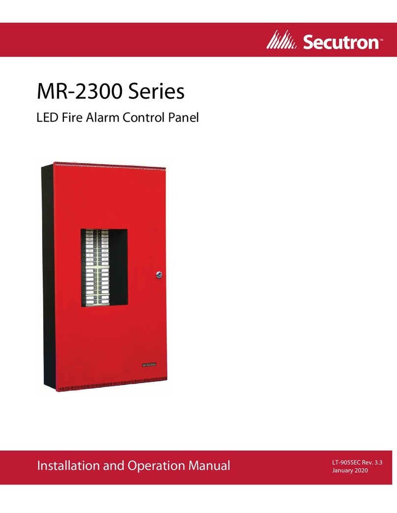
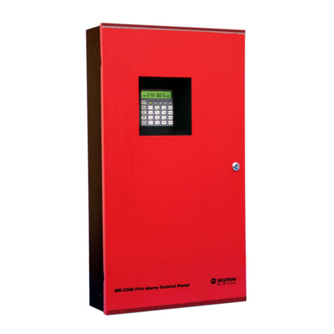
Figure 1 MR-2300 LCD Series ..................................................................................................... 13
Figure 2 Enclosure dimensions, surface mount ........................................................................... 18
Figure 3 Enclosure dimensions, semi-flush mounting and trim ring ............................................. 19
Figure 4 Backbox and Trim Ring Dimensions for Models MR-2306-DR/MR-2306-DDR ............. 20
Figure 5 Flush trim detail (from above) ........................................................................................ 20
Figure 6 MMX-BBX-1024DS and MMX-BBX-1024DSR installation instructions and dimensions 21
Figure 7 Installation of adder modules for MR-2312 LCD ............................................................ 22
Figure 8 Installation of adder modules for MR-2306 LCD ............................................................ 23
Figure 9 Main fire alarm board connections, DIP switches and jumpers for MR-2312 LCD ........ 24
Figure 10 Main fire alarm board connections, DIP switches and jumpers for MR-2306 LCD ........ 25
Figure 11 MR-2300-A Input Class A converter adder module ....................................................... 26
Figure 12 MR-2300-NC4/MR-2300-NC2 Output Class A converter adder module ........................ 27
Figure 13 MR-2312-R12 twelve relay adder module ...................................................................... 28
Figure 14 MR-2312-R12/MR-2306-R6 Relay programming ........................................................... 28
Figure 15 MR-2306-R6 six relay adder module ............................................................................. 29
Figure 16 Polarity reversal and city tie module .............................................................................. 29
Figure 17 Initiating circuit – Class B wiring ..................................................................................... 31
Figure 18 Initiating circuit– Class A wiring ...................................................................................... 32
Figure 19 Indicating circuit – Class B wiring ................................................................................... 32
Figure 20 Indicating circuit –Class A wiring .................................................................................... 33
Figure 21 Four-wire smoke detector - Class B wiring .................................................................... 33
Figure 22 Dialer wiring ................................................................................................................... 34
Figure 23 Relay per zone (MR-2312-R12) Terminal connection .................................................... 34
Figure 24 Relay per zone (MR-2306-R6) Terminal connection ...................................................... 35
Figure 25 Connecting an FACP to a 3G4010CF Interface Device ................................................. 36
Figure 26 Polarity reversal and city tie module terminal connection .............................................. 37
Figure 27 Power supply connection ............................................................................................... 38
Figure 28 Battery connections ........................................................................................................ 42
Figure 29 LCD Display and control buttons .................................................................................... 44
Figure 30 Lamp test ....................................................................................................................... 46
Figure 31 Evacuation Codes .......................................................................................................... 49
Figure 32 MR-2300 main LCD display ........................................................................................... 54
Figure 33 Enter passcode .............................................................................................................. 54
Figure 34 Command Menu ............................................................................................................. 55
Figure 35 MR-2300 Config menu ................................................................................................... 56
Figure 36 Feature Config menu ..................................................................................................... 56
Figure 37 The event log ................................................................................................................. 65
Figure 38 Walk test confirmation .................................................................................................... 66
Figure 39 Walk test zones .............................................................................................................. 66
Figure 40 Walk test active .............................................................................................................. 66
Figure 41 i3 loop test confirmation ................................................................................................. 67
Figure 42 i3 test zones ................................................................................................................... 67
Figure 43 i3 test not ready .............................................................................................................. 68


