6
List of Figures
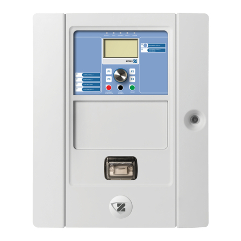
Figure 1 MR-2312-LDR ................................................................................................................ 13
Figure 2 Box dimensions .............................................................................................................. 18
Figure 3 Box dimensions, semi-flush mounting and trim ring ....................................................... 19
Figure 4 Flush trim detail (from above) ........................................................................................ 19
Figure 5 MMX-BBX-1024DS and MMX-BBX-1024DSR Installation Instructions and Dimensions 20
Figure 6 Installation of Adder Modules ......................................................................................... 21
Figure 7 Main Fire Alarm Board cable connector and jumper settings ........................................ 22
Figure 8 MR-2300-A Input Class A Converter Adder Module ...................................................... 23
Figure 9 MR-2300-NC4/MR-2300-NC2 Output Class A Converter Adder Module ...................... 24
Figure 10 MR-2312-R12 twelve relay adder module ...................................................................... 25
Figure 11 MR-2312-R12/MR-2306-R6 Relay programming ........................................................... 25
Figure 12 MR-2306-R6 six relay adder module ............................................................................. 26
Figure 13 Polarity reversal and city tie module .............................................................................. 26
Figure 14 Initiating circuit – Class B wiring ..................................................................................... 28
Figure 15 Initiating circuit– Class A wiring ...................................................................................... 29
Figure 16 Indicating circuit – Class B wiring ................................................................................... 30
Figure 17 Indicating circuit –Class A wiring .................................................................................... 30
Figure 18 Four-wire smoke detector - Class B wiring .................................................................... 31
Figure 19 Dialer wiring ................................................................................................................... 31
Figure 20 Relay per zone (MR-2312-R12) Terminal connection .................................................... 32
Figure 21 Relay per zone (MR-2306-R6) Terminal connection ...................................................... 32
Figure 22 Connecting an FACP to a 3G4010 Interface Device ..................................................... 33
Figure 23 Connecting an FACP to a 3G4010CF Interface Device outside Canada ....................... 34
Figure 24 Polarity reversal and city tie module terminal connection .............................................. 35
Figure 25 Power supply connection ............................................................................................... 36
Figure 26 Battery connections ........................................................................................................ 40
Figure 27 LED indicators and control buttons ................................................................................ 42
Figure 28 Alarm Circuit Indicator .................................................................................................... 46
Figure 29 LAMP TEST ................................................................................................................... 50
Figure 30 Evacuation and Alert Codes ........................................................................................... 54
Figure 31 Open Circuit Trouble ...................................................................................................... 58
Figure 32 Communication Trouble ................................................................................................. 58
Figure 33 Dirty Device Trouble ....................................................................................................... 58
Figure 34 Out of sensitivity Trouble ................................................................................................ 58
Figure 35 Freeze Trouble ............................................................................................................... 59
Figure 36 MR-2300 Configuration .................................................................................................. 62
Figure 37 Enter passcode .............................................................................................................. 63
Figure 38 Command Menu ............................................................................................................. 63
Figure 39 MR-2300 Config menu ................................................................................................... 64
Figure 40 Feature Config menu ..................................................................................................... 65
Figure 41 The event log ................................................................................................................. 77
Figure 42 Select Log ...................................................................................................................... 78
Figure 43 Clear all the selected logs .............................................................................................. 78


