See Water Oil Smart User manual

Oil Smart® Simplex Panel
Installation Manual
Oil Smart® Simplex System:
The Oil Smart® OSSIM-30 System incorporates pump
controls and alarm sensors that differentiate between
oil and water, allowing companies to responsibly
discharge the water without the risk of pumping oil.
Installation of the Simplex Panel keeps companies
in compliance with Elevator Code ASME A17.1 and
State/Federal regulations while reducing the risk of
adverse publicity, nes and expensive cleanup costs.
OSSIM-30
Single Phase 120/208/240V 60Hz.
(0-16.0 Pump Full Load Amps)
Features:
• Oil Smart® and Liquid Smart® Controls with 20’
cords and mounting hardware
• NEMA 4X Panel Enclosure: Heavy Duty
Polycarbonate, 10″x8″x4″, Clear Front
• CSA International Certied No. 229294
• UL Listed for the United States and Canada
• High Liquid Alarm with Test and Silence Features,
Red Beacon Alarm Light, White Light for Water
Present, Yellow Light for Oil Present
• Alarm Horn that Sounds at 85 Decibels at 10 Feet
• Complete Panel Remote Monitoring Dry Contacts:
Oil, Water, High Liquid
• HOA Switch and Green Light for Pump Run
Panel and Component Installation:
1. Caution: To maintain the NEMA 4X rating, make
all wiring connections with seal tight cable grips or
conduit connections (supplied by end user).
2. Determine mounting location for control panel. Mount
panel using mounting feet supplied.
3. The control panel should not be mounted in an
area that is subject to submersion.
4. It is recommended to use separate 120VAC sources
for the pump and alarm circuits.
5. Run pump cable, Liquid Smart® cable, and Oil
Smart® cable through conduit. Make eld connections
as shown on wiring diagram.
6. Run power line conductor through conduit. Wire to
terminals per enclosed schematic. Branch circuit
protection to be provided by end-user.
7. Mount Oil Smart Pump Control and Liquid Smart
Sensor with provided mounting hardware to pump
discharge pipe. The off sensor of the Oil Smart Switch
shall be positioned at least 3” above the impeller
of the pump. The Liquid Smart Sensor shall be
positioned at the appropriate high liquid level point.
Start up:
1. When power is applied, the green power light located
on the white front swing panel shall light.
2. The Pump HOA Switch shall be placed to the A (auto)
position to ensure the system will pump. The pump
can be tested or turned on manually if the HOA switch
is in the H (Hand-Manual) position.
To test the alarm circuit, push the test button on the front
panel, the audible alarm shall sound and the red beacon
will light.
Service:
Caution: Before checking electrical connections within
the control or attempting to replace any components,
turn off all branch circuits supplying power to the main
control panel.
Protecting the Environment since 1995.
www.seewaterinc.com
or www.oilsmart.org
951.487.8073 • 888.733.9283
Email: info@seewaterinc.com
121 North Dillon Avenue • San Jacinto, CA 92583
P.O. Box 1269 • San Jacinto, CA 92581
lacirtcelElanoitaNehthtiwecnadroccaniebtsumsnoitallatsnillA.1
Code, and any other applicable state and local electrical
requirements.
1. The switch and pump are not rated for explosive environments.
This product is intended for hydraulic oils only.
IM 701, Rev. 0515

Oil Smart® Simplex Panel
Installation Manual
WATER
WATER
OIL
LAYER
WATER
OIL
LAYER
Normal Condition (Water Only)
When water comes in contact with
the short (on) sensor, the pump will
turn on. The pump will remain on
until water clears the long (off) sen-
sor.
Oil Present Condition
If oil comes in contact with the (on)
sensor, the pump will not turn on.
Water (Oil Present Condition)
If the water level rises enough to
contact the (on) sensor under the oil
layer, the pump will turn on and re-
main on until the (off) sensor clears
of water.
Oil Smart® Switch Operation:
Testing:
Liquid Smart® Alarm Testing
Oil Test: Submerge both sensors in oil and the
amber oil indicator on the front panel will light.
Water Test: Submerge both sensors in water and
the white water indicator on the front panel will
light.
Both tests will turn on the red beacon alarm light
and sound the alarm buzzer.
Oil Smart® Pump Switch Testing
Place your thumb on the short sensor of the Oil
Smart® Pump Switch and the pump will turn
on. While touching the short “on” sensor, touch
the long “off” sensor with your ngers. Remove
your thumb from the on sensor and begin to
move your ngers down the off sensor. Remove
your ngers from off sensor and the pump will
turn off. Optional: Fill up sump area with water,
when water reaches the on sensor, the pump will
turn on and remain on until water clears the off
sensor.
Typical Installation for Oil Smart® Pump Switch
and Alarm System
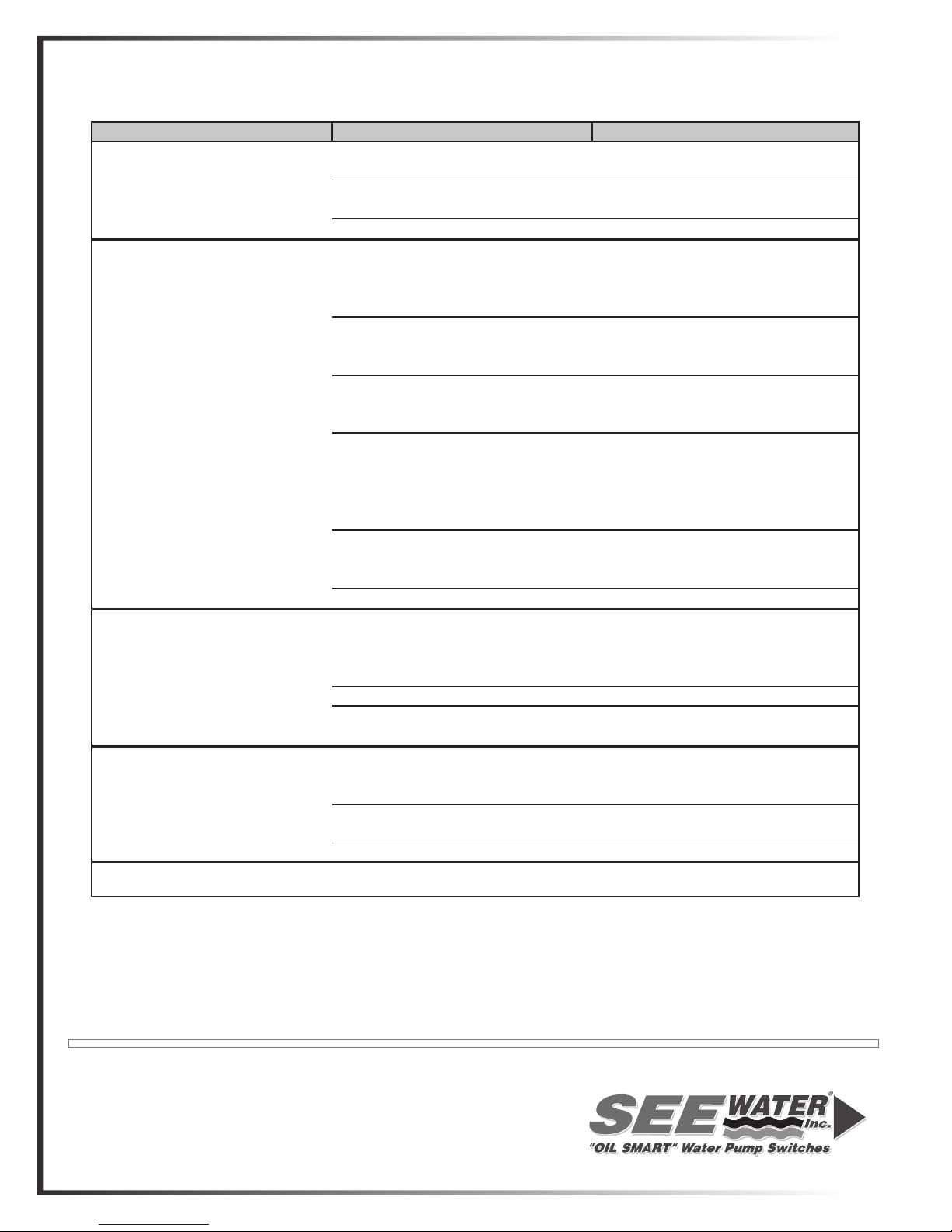
Problem Possible Cause Solution
Pump Control does not activate Incorrect Polarity Make sure phase and neutral are
the pump. Pump does not run. not reversed.
Loose connection in control panel. Confirm all connections are tight
or electrical system. and secure.
Defective Control Replace Control
Pump Control is not operating Problem with electrical system Check electrical circuits for
properly; not consistant or common neutrals;
staying on. may cause switch to not function
correctly.
Improper Field Wiring Do not run DC conductors
through same conduit as AC
conductors.
Control is not clean of conductive White plastic case must be kept clean.
material. Clean with houehold rubbing
alcohol and rag.
Improper Mounting of Components Keep control (1" to 2") clear of
any metallic material. Mount to pvc
pipe or if mounting to metal pipe, make
sure to mount with See Water
quick mount PVC bracket.
Float switch attached to pump Float switch must be removed,
secured in manual operation, or
replaced with correct pump.
Defective Control and/or Pump(s) Replace Control and/or Pump(s)
Alarm will not activate Power supply failure Confirm separate 120V power to
circuit board. Can be jumpered
from incoming power on pump
terminal if 120v is available.
Defective Alarm Sensor Replace Alarm Sensor
Loose connection in control panel. Confirm all connections are tight
or electrical system. and secure.
Pump will not turn on or pump is Incorrect match on control panel Confirm correct pump voltage and
not functioning properly. and pump. wires matched to correct control
panel
Loose connection in control panel. Confirm all connections are tight
or electrical system. and secure.
Defective Pump(s) Replace Pump(s)
Oil Smart Control Panel Troubleshooting Guide
Any technical questions on this product should be directed to See Water, Inc at 888-733-9283.
Protecting the Environment since 1995.
www.seewaterinc.com or www.oilsmart.org
951.487.8073 • 888.733.9283 • Email: [email protected]
121 North Dillon Street • San Jacinto, CA 92583
P.O. Box 1269 • San Jacinto, CA 92581
This manual suits for next models
1
Popular Control System manuals by other brands


Aqua Control
Aqua Control DOS CL 2 Deluxe WIFI Salz manual

flakt woods
flakt woods eq Controls Assembly and installation

WatchDog
WatchDog 3452H product manual

A/DA
A/DA Platinum Elite installation manual

Fly Sky
Fly Sky Paladin PL18 user manual

Securakey
Securakey Radio Key RK-600 Installation & operating guide


