A/DA Platinum Elite User manual

INSTALLATION MANUAL
ZONE CONTROL SYSTEM

2
CONTENTS
3
1
1.Precautions 2
2.EnvironmentalInformation 2
3.Components 3
4.OptionalComponents 3
5.MountingtheControlBox
Assembly 4
6.ConnectingtheZoneDampers 4
7.ConnectingtheAC 5
8. 6
9.ACControl-SamsungNASA
WiringDiagram 8
CommissioningNotes 9
MountingtheTablet
10.ACControl-SamsungNoNASA
WiringDiagram 10
CommissioningNotes 11
11.ACControl-Daikin
WiringDiagram 12
CommissioningNotes 13
12.ACControl-Fujitsu
WiringDiagram 14
CommissioningNotes 15
13.ACControl-MitsubishiElectric
WiringDiagram 16
CommissioningNotes 17
1
14.ACControl-MitsubishiHeavy
WiringDiagram 18
CommissioningNotes 19
15.ACControl-Panasonic
WiringDiagram 20
CommissioningNotes 21
16.ACControl-Toshiba
WiringDiagram 22
CommissioningNotes 23
AccessingSystemSetUp
25.ResetDefault 39
17.ZoneSetUp 24
18.SettingACControl 28
19.Wi-FiConnection 30
20.SoftwareUpdate 31
21.DownloadingandInstalling
PlatinumEliteApp 32
22. 33
23.AddingaZone 37
24.AddingaSensor 37
25.AddinganAC 38
26.Warranty 41
27.Troubleshooting 42
28.ZoneSetupSheet 44

3. Components
4. Optional Components
Tablet (TB01) Control Box Assembly (RMC04 & MA01)
240V Twin IEC AC Power Cord (PETWP) 15m Cat6 Coms Cable (PECC15)
24V DC Power Supply (PEPS)
Platinum Elite Gateway - to suit AC brand
PEGSN (NASA) PEGM
PEGS (NO NASA) PEGMHI
PEGD PEGP
PEGF PEGT
2, 3 & 4-core AC Link Cable (PETCW, PE3CW, PE4CW) -for use with Platinum Elite Gateway
Wireless Temperature Sensor (PEWZS) Duct Sensor (PEDS) Wireless Receiver (PEWRM)
Plug-in Temperature Sensor (PEPZS)
30m Cat6 Coms Cable (PECC30)
1. Precautions
2. Environmental Information
Refer to these installation instructions before commencing the installation or service of this
product.
WARNING
This product should be installed and setup by qualified personnel.
To reduce the risk of fire, electric shock or product damage:
DO NOT expose to rain or moisture of any kind
DO NOT place articles filled with water on or near this appliance
DO NOT remove covers – there are no serviceable part inside
DO use only genuine Air Diffusion Agencies components
Ensure all electrical connections are made before connecting power to the Control Box
Assembly.
Installation setup changes should only be attempted by qualified personnel.
This product (including packaging) is manufactured from fully recyclable components.
Please dispose of in an appropriate manner.
RECYCLE
PRECAUTIONS
INSTALLATION MANUAL
23
COMPONENTS
DAIKIN

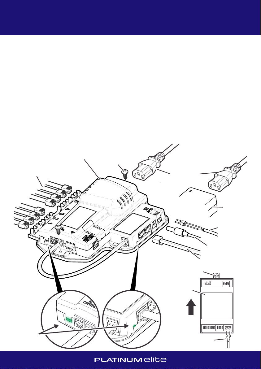
5. Mounting the Control Box Assembly
6. Connecting the Zone Dampers
7. Connecting the AC
ŸMount the Control Box Assembly in the roof space in a location central to all of the Zone
Dampers, ideally near a ceiling access panel.
ŸMount in a well ventilated area and as far away from the roof surface as possible.
ŸThe Control Box Assembly should be screwed to the roof structure at a level to provide
easy access for the connection of cables.
DO NOT cover the Control Box Assembly with insulation
DO NOT mount below water heaters.
DO NOT mount near or below water pipes.
DO NOT mount near power cables or other sources of electrical noise.
ŸPlug in the DC power supply to the Modbus Adapter socket and connect the twin plug IEC
power cord to the Control Box Assembly and the DC Power Supply.
ŸPlug in the Coms Cable from the wall mounted Tablet.
Ÿ
ŸThe last step is to plug in the power cord to a standard power outlet. The power outlet
must be fitted by a licenced electrician.
DO NOT power up the Control Box Assembly until all connections are made.
ŸPlug in the Zone Damper cables to the Control Box, starting at position number 1 and
continuing with adjacent consecutive sockets.
Ÿ
ŸRecord the position and size of each Zone Damper on the record sheet in the back of this
manual, noting which, if any, are designated as Relief Zones.
It is recommended to use an off-the-shelf cable tester to check the Coms Cable prior to
installation and in particular, after being pulled through a wall cavity.
Only Zone Damper cables and joiners (if necessary) supplied by Air Diffusion Agencies
must be used. It is recommended to use an off-the-shelf cable tester to check Zone
Damper cables prior to installation.
more information r
All AC systems must be fully commissioned and tested with a standard AC Wall Controller
connected to the AC Indoor Unit to complete necessary field settings and to confirm the AC
runs normally.
efer to the relevant brand AC
Commissioning Notes provided and the Platinum Elite Gateway instruction sheet. In
general, to connect the AC to the Zone Control System:
Ideally, the standard AC Wall Controller should be mounted away from the
Platinum Elite Tablet, ie. in a discrete but accessible location such as a utility room, a
cupboard or in the roof space near a ceiling access panel. This allows for easy access should
the AC unit require adjustments to the factory settings by qualified personnel. The system
will use the default return air temperature of the AC Indoor Unit as the reference
temperature for AC control. For
MOUNTING THE CONTROL BOX CONNECTING THE AC
INSTALLATION MANUAL
45
240VAC
Power Cord
Control Box Assembly
Zone Damper Cables
Mounting Screw
Coms Cable (to Tablet)
24VDC
Power
Supply
From 24VDC
Power Supply
AC Link Cable
to Gateway
Ÿ
as far from the roof surface as possible and
Ÿ
Ÿ
Ensure power is off and refer to the relevant brand AC Control Wiring Diagrams to connect
the Gateway. All Gateways require the 2-core AC Link Cable (PETCW) for the A+B-
connection to the Control Box Assembly.
ŸIt is recommended to mount the Gateway
vertically, using the pull-out mounting tabs provided.
ŸRefer to DIP switch settings (if applicable) on the AC Control Wiring Diagrams.
After completing wiring and setting the DIP switches, power up the system. AC Unit,
Platinum Elite Gateway and Platinum Elite Zone Control System can be powered up at the
same time, but if powered up separately, ensure AC Unit and Platinum Elite Gateway are
on before the Platinum Elite Zone Control System.
The system should automatically detect the Platinum Elite Gateway during the setup
process. (If the Gateway is added after the initial setup process, on the Zone Setup screen
it will be necessary to perform a ‘Recheck’ to allow the Gateway to be detected.) Follow
the onscreen prompts to complete the AC setup.
supplied
LED light
indicates
power
Mounting Screw
AC Link Cable to
Control Box Assembly
AC Link Cable to
Control Box Assembly
A+B-
Platinum Elite
Gateway
Platinum Elite
Gateway
UPUP
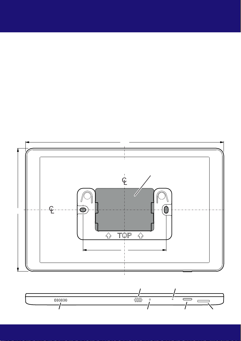
MOUNTING THE TABLET
8. Mounting the Tablet
ŸMount the Tablet where the standard AC wall control would normally be mounted,
approximately 1.5m above floor level and preferably on an internal wall in the return air
flow. Ensure at least a 100mm ‘exclusion zone’ to any other wall mounted item.
ŸIf using in conjunction with a standard AC wall control, it is recommended not to mount
the Tablet below the AC control to prevent any radiant heat inadvertently affecting the AC
temperature sensor.
ŸAvoid mounting in direct sunlight.
ŸAvoid mounting in direct airflow of an AC vent.
ŸThe Mounting Plate is used as a template for marking the wall before mounting. Refer
diagram below to cut the hole required in the wall to accommodate the socket on the
back of the Tablet.
ŸThe Mounting Plate can be attached to a wall using or to a standard wall
switch bracket. supplied fixings
INSTALLATION MANUAL
67
124124
Plug Coms Cable into socket on
the back of the Tablet, then
simply push Tablet onto the
Mounting Plate and slide down
so it clips into place
Mounting Plate
Mounting Screw
Coms Cable
Tablet
200200
8484
Speaker
Factory ResetTemperature Sensor
SD Card
Power LED Power On/Off
MOUNTING THE TABLET
NOTE: Ensure wall behind opening in
Mounting Plate is completely clear
100mm ‘exclusion zone’ to any
other wall mounted items
100100
100100

MOUNTING THE TABLET
8. Mounting the Tablet
ŸMount the Tablet where the standard AC wall control would normally be mounted,
approximately 1.5m above floor level and preferably on an internal wall in the return air
flow. Ensure at least a 100mm ‘exclusion zone’ to any other wall mounted item.
ŸIf using in conjunction with a standard AC wall control, it is recommended not to mount
the Tablet below the AC control to prevent any radiant heat inadvertently affecting the AC
temperature sensor.
ŸAvoid mounting in direct sunlight.
ŸAvoid mounting in direct airflow of an AC vent.
ŸThe Mounting Plate is used as a template for marking the wall before mounting. Refer
diagram below to cut the hole required in the wall to accommodate the socket on the
back of the Tablet.
ŸThe Mounting Plate can be attached to a wall using or to a standard wall
switch bracket. supplied fixings
INSTALLATION MANUAL
67
124124
Plug Coms Cable into socket on
the back of the Tablet, then
simply push Tablet onto the
Mounting Plate and slide down
so it clips into place
Mounting Plate
Mounting Screw
Coms Cable
Tablet
200200
8484
Speaker
Factory ResetTemperature Sensor
SD Card
Power LED Power On/Off
MOUNTING THE TABLET
NOTE: Ensure wall behind opening in
Mounting Plate is completely clear
100mm ‘exclusion zone’ to any
other wall mounted items
100100
100100
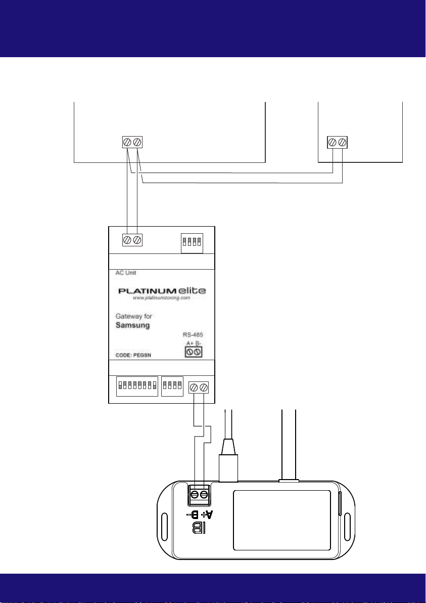
AC CONTROL - SAMSUNG NASA
9. AC Control - Samsung NASA
Wiring Diagram Commissioning Notes
Advanced Installation
NOTE: This Gateway will only work with a Samsung Wall Controller with NASA protocol.
ŸWire Platinum Elite Zone Control System, Gateway and AC Indoor Unit as shown ensuring
all wires are securely connected. Unless otherwise specified, leave DIP switches in their
default position.
ŸInitialise the AC Unit with the Samsung Wall Controller connected.
Ÿ
The Wall Controller
can be wired in parallel with the Gateway. Ensure the AC control temperature is set to be
measured from the AC return air sensor.
ŸFollow the Platinum Elite onscreen prompts to complete the AC setup.
The Platinum Elite system is capable of providing an external reference temperature to
compatible AC Units from either the temperature sensor in the Tablet or one of the
connected Temperature Sensors. Utilising this feature will potentially modify the control
loop for the AC Unit and as such requires precise configuration of the AC Unit, the Platinum
Elite Gateway and the Platinum Elite Tablet software to ensure the system functions
correctly.
For detailed information on Samsung AC Unit system compatibility utilising external
reference temperatures and related Advanced Installation options, please visit the Platinum
Elite Zone Control System website www.platinumzoning.com or contact your ADA
distributor.
AC Unit, Gateway and Platinum Elite Zone Control System can be powered up at the same
time, but if powered up separately, ensure AC Unit and Gateway are on before the
Platinum Elite Zone Control System.
INSTALLATION MANUAL
89
2-core cable (PETCW)
supplied with Platinum
Elite Cable Kit
Tablet
Cat6 cable
24VDC
Power
Supply
AC Indoor Unit PCB
Platinum Elite
Gateway
PEGSN
SW1
SW3 SW4
Gateway Address Setting
Gateway No.
ON 1 (Default)
SW3
ON
ON
ON
2
3
4
A+ B-
F3 F4
F3 F4
2-core cable (PETCW)
supplied with Platinum
Elite Cable Kit
F3 F4
Wall Controller
SW1 ON
Default Gateway Setting
Down/OFF Up/ON
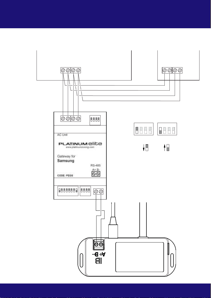
AC CONTROL - SAMSUNG NO NASA
INSTALLATION MANUAL
10 11
10. AC Control - Samsung No NASA
Wiring Diagram Commissioning Notes
Advanced Installation
ŸWire Platinum Elite Zone Control System, Gateway and AC Indoor Unit as shown ensuring
all wires are securely connected. Unless otherwise specified, leave DIP switches in their
default position.
ŸInitialise the AC Unit with the Samsung AC Wall Controller connected.
Ÿ
The Wall Controller
can be wired in parallel with the Gateway. Ensure the AC control temperature is set to be
measured from the AC return air sensor.
After commissioning, SW1.1 is left OFF. Gateway is in Slave mode.
ŸAC Unit, Gateway and Platinum Elite Zone Control System can be powered up at the same
time, but if powered up separately, ensure AC Unit and Gateway are on before the
Platinum Elite Zone Control System.
ŸFollow the Platinum Elite onscreen prompts to complete the AC setup.
The Platinum Elite system is capable of providing an external reference temperature to
compatible AC Units from either the temperature sensor in the Tablet or one of the
connected Temperature Sensors. Utilising this feature will potentially modify the control
loop for the AC Unit and as such requires precise configuration of the AC Unit, the Platinum
Elite Gateway and the Platinum Elite Tablet software to ensure the system functions
correctly.
For detailed information on Samsung AC Unit system compatibility utilising external
reference temperatures and related Advanced Installation options, please visit the Platinum
Elite Zone Control System website www.platinumzoning.com or contact your ADA
distributor.
Tablet
Cat6 cable
24VDC
Power
Supply
AC Indoor Unit PCB
Platinum Elite
Gateway
PEGS
SW1
SW3 SW4
SW1 Slave Master
ON ON
Gateway Master/Slave Setting
A+ B-
F3 F4V1 V2
F3 F4V1 V2
2-core cable (PETCW)
supplied with Platinum
Elite Cable Kit
4-core cable (PE4CW)
supplied with Platinum
Elite Cable Kit
Down/OFF Up/ON
F3 F4
Wall Controller
V1 V2
SW1 ON
Default Gateway Setting
Down/OFF Up/ON
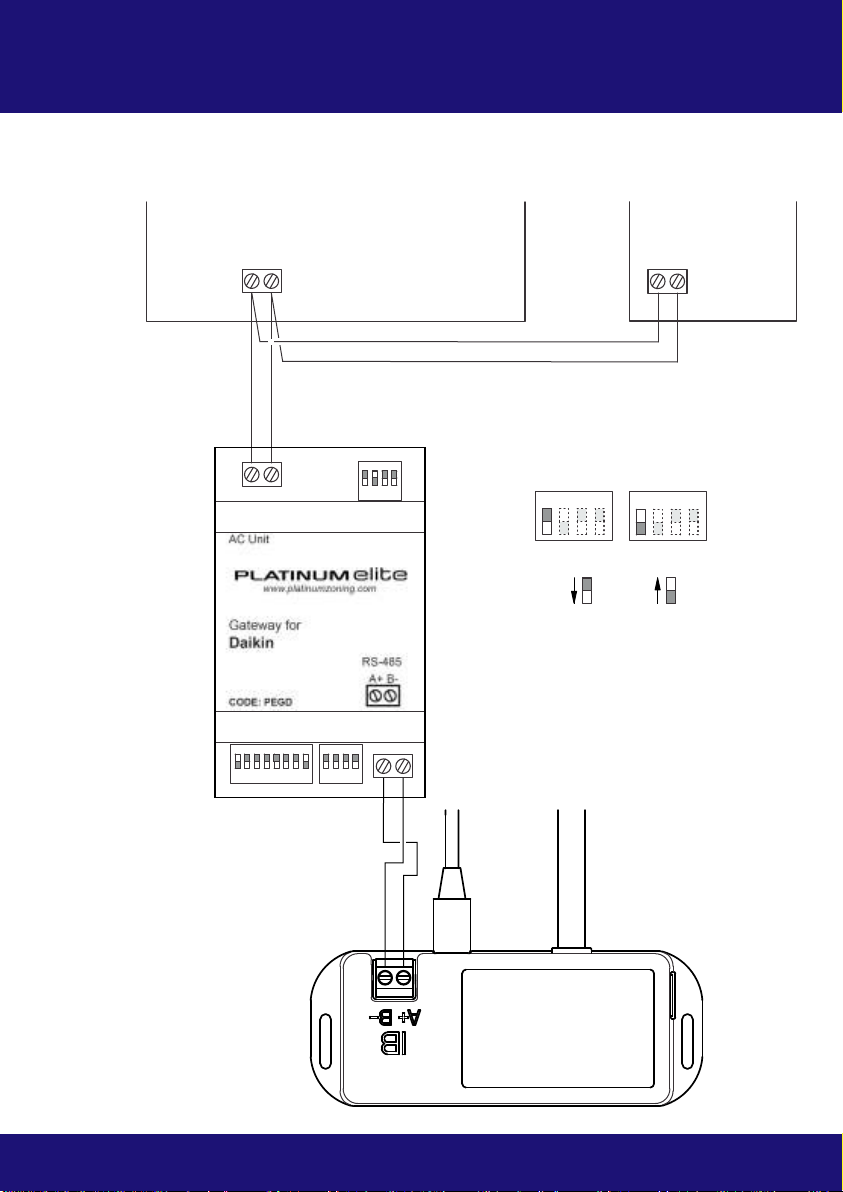
AC CONTROL - DAIKIN
11. AC Control - Daikin
Wiring Diagram
INSTALLATION MANUAL
12 13
Commissioning Notes
Advanced Installation
ŸWire Platinum Elite Zone Control System, Gateway and AC Indoor Unit as shown ensuring
all wires are securely connected. Unless otherwise specified, leave DIP switches in their
default position.
NOTE: In early models, the Daikin Gateway was supplied with SW1.4 ON as default - this
must be changed to OFF as shown by Default Gateway Setting above.
ŸInitialise the AC Unit with the Daikin AC Wall Controller connected.
Ÿ
The Wall Controller
can be wired in parallel with the Gateway. Ensure the AC control temperature is set to be
measured from the AC return air sensor.
ŸAfter commissioning, SW1.1 is left OFF. Gateway is in Slave mode.
ŸFollow the Platinum Elite onscreen prompts to complete the AC setup.
The Platinum Elite system is capable of providing an external reference temperature to
compatible AC Units from either the temperature sensor in the Tablet or one of the
connected Temperature Sensors. Utilising this feature will potentially modify the control
loop for the AC Unit and as such requires precise configuration of the AC Unit, the Platinum
Elite Gateway and the Platinum Elite Tablet software to ensure the system functions
correctly.
For detailed information on Daikin AC Unit system compatibility utilising external reference
temperatures and related Advanced Installation options, please visit the Platinum Elite Zone
Control System website www.platinumzoning.com or contact your ADA distributor.
AC Unit, Gateway and Platinum Elite Zone Control System can be powered up at the same
time, but if powered up separately, ensure AC unit and Gateway are on before the
Platinum Elite Zone Control System.
Tablet
Cat6 cable
24VDC
Power
Supply
AC Indoor Unit PCB
Platinum Elite
Gateway
PEGD
SW1
SW3 SW4
SW1 Slave Master
ON ON
Gateway Master/Slave Setting
A+ B-
P1 P2
P1 P2
2-core cable (PETCW)
supplied with Platinum
Elite Cable Kit
2-core cable (PETCW)
supplied with Platinum
Elite Cable Kit
(P1P2 connection has
no specific polarity)
Down/OFF Up/ON
DAIKIN
Wall Controller
P1 P2
SW1 ON
Default Gateway Setting
Down/OFF Up/ON

AC CONTROL - FUJITSU
INSTALLATION MANUAL
14 15
12. AC Control - Fujitsu
Wiring Diagram
Tablet
Cat6 cable
24VDC
Power
Supply
AC Indoor Unit PCB
Platinum Elite
Gateway
PEGF
SW1
SW3 SW4
SW1 Slave Master
ON ON
Gateway Master/Slave Setting
A+ B-
B W R
(3 2 1)
B W R
(3 2 1)
Commissioning Notes
Advanced Installation
ŸWire Platinum Elite Zone Control System, Gateway and AC Indoor Unit as shown ensuring
all wires are securely connected. Unless otherwise specified, leave DIP switches in their
default position.
ŸInitialise the AC Unit with the Fujitsu AC Wall Controller connected.
ŸAfter , SW1.1 is left OFF - Gateway is in Slave mode.
Ÿ
The Wall Controller
can be wired in parallel with the Gateway.
commissioning
Ensure the AC control temperature is set to be
measured from the AC return air sensor.
Follow the Platinum Elite onscreen prompts to complete the AC setup.
The Platinum Elite system is capable of providing an external reference temperature to
compatible AC Units from either the temperature sensor in the Tablet or one of the
connected Temperature Sensors. Utilising this feature will potentially modify the control
loop for the AC Unit and as such requires precise configuration of the AC Unit, the Platinum
Elite Gateway and the Platinum Elite Tablet software to ensure the system functions
correctly.
For detailed information on Fujitsu AC Unit system compatibility utilising external reference
temperatures and related Advanced Installation options, please visit the Platinum Elite Zone
Control System website www.platinumzoning.com or contact your ADA distributor.
ŸAC Unit, Gateway and Platinum Elite Zone Control System can be powered up at the same
time, but if powered up separately, ensure AC unit and Gateway are on before the
Platinum Elite Zone Control System.
2-core cable (PETCW)
supplied with Platinum
Elite Cable Kit
3-core cable (PE3CW)
supplied with Platinum
Elite Cable Kit
Down/OFF Up/ON
Wall Controller
B W R
(3 2 1)
SW1 ON
Default Gateway Setting
Down/OFF Up/ON
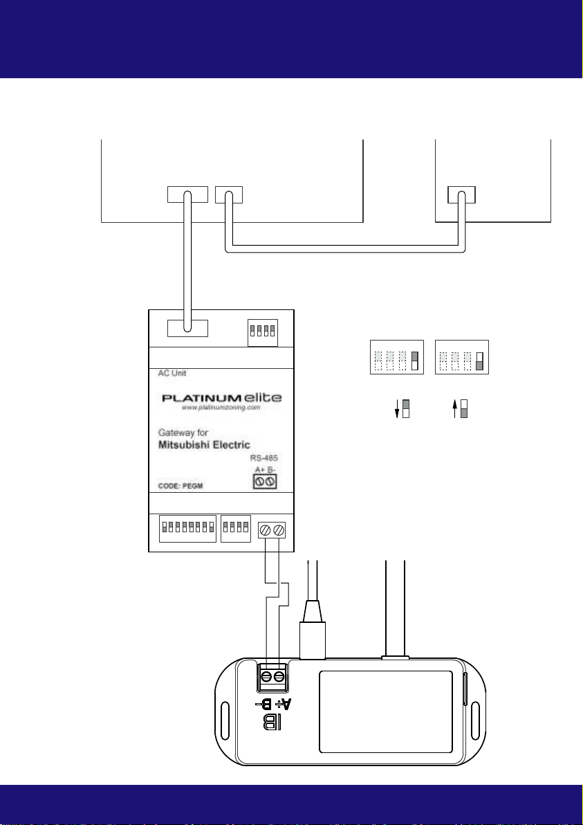
AC CONTROL - MITSUBISHI ELECTRIC
INSTALLATION MANUAL
16 17
13. AC Control - Mitsubishi Electric
Wiring Diagram
Cable with plugs,
supplied with Gateway
Tablet
Cat6 cable
24VDC
Power
Supply
AC Indoor Unit PCB
Platinum Elite
Gateway
PEGM
SW1
SW3 SW4
SW1 3 or 4 2
ON ON
Fan Speed Setting
A+ B-
CN105
Commissioning Notes
Advanced Installation
ŸWire Platinum Elite Zone Control System, Gateway and AC Indoor Unit as shown ensuring
all wires are securely connected. Unless otherwise specified, leave DIP switches in their
default position.
ŸCheck the number of fan speeds available on the AC Indoor Unit and if necessary, modify
the SW1.4 switch as shown by the Fan Speed Setting on the Wiring Diagram page. The
default setting is 3 or 4.
ŸInitialise the AC Unit with the Mitsubishi Electric AC Wall Controller connected.
Mitsubishi Electric
Ensure the
AC control temperature is set to be measured from the AC return air sensor.
ŸFollow the Platinum Elite onscreen prompts to complete the AC setup.
The Platinum Elite system is capable of providing an external reference temperature to
compatible AC Units from either the temperature sensor in the Tablet or one of the
connected Temperature Sensors. Utilising this feature will potentially modify the control
loop for the AC Unit and as such requires precise configuration of the AC Unit, the Platinum
Elite Gateway and the Platinum Elite Tablet software to ensure the system functions
correctly.
For detailed information on AC Unit system compatibility utilising
external reference temperatures and related Advanced Installation options, please visit the
Platinum Elite Zone Control System website www.platinumzoning.com or contact your ADA
distributor.
ŸAC Unit, Gateway and Platinum Elite Zone Control System can be powered up at the same
time, but if powered up separately, ensure AC Unit and Gateway are on before the
Platinum Elite Zone Control System.
2-core cable (PETCW)
supplied with Platinum
Elite Cable Kit
Down/OFF Up/ON
Wall Controller
SW1 ON
Default Gateway Setting
Down/OFF Up/ON

AC CONTROL - MITSUBISHI HEAVY
INSTALLATION MANUAL
18 19
14. AC Control - Mitsubishi Heavy Industries
Wiring Diagram
Tablet
Cat6 cable
24VDC
Power
Supply
AC Indoor Unit PCB
Platinum Elite
Gateway
PEGMHI
SW1
SW3 SW4
SW1 Slave Master
ON ON
Gateway Master/Slave Setting
A+ B-
X Y
X Y
SW1 12
ON ON
Fan Speed Setting
34
ON ON
Commissioning Notes
Advanced Installation
ŸWire Platinum Elite Zone Control System, Gateway and AC Indoor Unit as shown ensuring
all wires are securely connected. Unless otherwise specified, leave DIP switches in their
default position.
ŸCheck the number of fan speeds available on the AC Indoor Unit and if necessary, modify
the SW1.2 and SW1.3 switches as shown by the Fan Speed Setting on the Wiring Diagram
page. The default setting is 4.
ŸInitialise the AC Unit with the Mitsubishi Heavy Industries AC Wall Controller connected.
ŸAfter , SW1.1 is left OFF - Gateway is in Slave mode. The AC return air
sensor will be used as the default reference temperature sensor for AC control.
Mitsubishi Heavy Industries
The Wall Controller can be wired in parallel with the Gateway.
commissioning
Ensure the AC control
temperature is set to be measured from the AC return air sensor.
ŸFollow the Platinum Elite onscreen prompts to complete the AC setup.
The Platinum Elite system is capable of providing an external reference temperature to
compatible AC Units from either the temperature sensor in the Tablet or one of the
connected Temperature Sensors. Utilising this feature will potentially modify the control
loop for the AC Unit and as such requires precise configuration of the AC Unit, the Platinum
Elite Gateway and the Platinum Elite Tablet software to ensure the system functions
correctly.
For detailed information on AC Unit system compatibility
utilising external reference temperatures and related Advanced Installation options, please
visit the Platinum Elite Zone Control System website www.platinumzoning.com or contact
your ADA distributor.
ŸAC Unit, Gateway and Platinum Elite Zone Control System can be powered up at the same
time, but if powered up separately, ensure AC unit and Gateway are on before the
Platinum Elite Zone Control System.
2-core cable (PETCW)
supplied with Platinum
Elite Cable Kit
2-core cable (PETCW)
supplied with Platinum
Elite Cable Kit
(XY connection has no
specific polarity)
Down/OFF Up/ON
Wall Controller
X Y
SW1 ON
Default Gateway Setting
Down/OFF Up/ON
Other manuals for Platinum Elite
1
Table of contents
Other A/DA Control System manuals


Popular Control System manuals by other brands


Simple
Simple XWS7-1001 user manual

Whelen Engineering Company
Whelen Engineering Company CanTrol Installation & operating guide

BRONKHORST
BRONKHORST E-7000 Series instruction manual

TouchTronics
TouchTronics 1210-R Service manual

Elstat
Elstat ems25 Series product manual

Raven
Raven SCS 360 Installation & service manual