See Water Radar Pro RPRO-2000 User manual

Radar Pro™ Level Sensor
Installation and Operation Manual
RPRO-2000
Electrical Properties:
Mechanical Properties:
Operating Condition:
Features:
Dimensions:
• Power Requirement: 12-30 VDC
• Output Signal: 4-20 mA DC, two wire
• Scanning Frequency: 76-81 GHz
• Electrical Connection: Wire pigtail
• Accuracy: ±2 mm
• Working Pressure: -1~3 bar
• Material: Polycarbonate & Fiberglass
• Wetted Materials: PVDF
• Protection Class: IP67
• Operating Temperature: -40 - 85°C
(-104 - 185°F)
72
∅76
29.5
G1-1/2
G1
24
125.5
• High precision ±2mm
• No-contact measurement
• Resistant to condensation, rain, and corrosion
• Operation is unaected by temperature, pressure or vacuum; provides
accurate readings under all environmental conditions
• High sensitivity, lightweight, easy integration
• Two-year limited warranty
Page 1-2 IM 5311 REV. 12/23
Model Range: ft(m) Cable Length: ft(m)
RPRO-2000 32ft (10m) 50ft (15m)
www.seewaterinc.com
951.487.8073 • 888.733.9283 • [email protected]
22220 Opportunity Way, Suite 101 • Riverside, CA 92518
Radar Pro™ Level Sensor
See Water’s Radar Pro™ Level Sensor is a high-precision ultra-low-power
millimeter-wave radar level sensor developed and designed for high
measurement accuracy, high sensitivity, easy integration, and superior
interaction performance.
The Radar Pro™ uses non-contact technology, eliminating the need for physical
contact with the measured substance, preventing contamination and minimizing
maintenance requirements. This sensor can be used in various industries and
applications, including liquids, distance, and harsh environments—such as
chemical, oil and gas, wastewater treatment, and food processing.
Radar Pro™ Level Sensor
Installation and Operation Manual
RPRO-2000
Warranty:
1. Wiring diagram of current (voltage) output connect with secondary unit.
2. Wiring diagram of serial output connecting with PC
External power / instrument / 485-232 / PC
Wiring Connection:
Instrument Secondary Instrument
Red
Yellow
Black
Supply + DC24V / 100mA Voltage Output
Input
GND
Output Supply -
DC Regulated
Voltage
Standard
Serial Port
Supply +
A
B
Output A
Output B
Supply -
Page 2-2 IM 5311 REV. 12/23
See Water, Inc. warrants that products of its
manufacture are free from defects in material and
workmanship for a period of 2 years from the date of
purchase. This date shall be determined by the date
on the invoice and the serial number on the product.
Replacement of the product is at the discretion of See
Water, Inc. This warranty is valid when the product
is installed in compliance with the manufacturer’s
installation instructions. The manufacturer’s obligation
under this warranty shall be limited to the repair or
replacement of any parts found by the manufacturer
to be defective.
www.seewaterinc.com
951.487.8073 • 888.733.9283 • [email protected]
22220 Opportunity Way, Suite 101 • Riverside, CA 92518
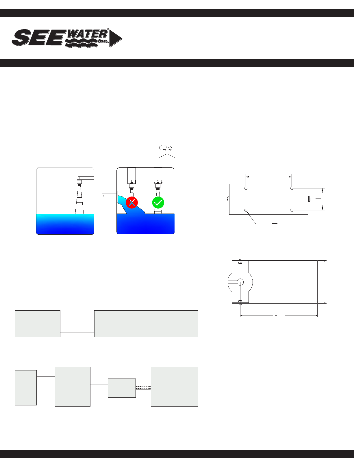
Installation:
Radar Sensor:
The Radar Pro™ should be installed over the top of the tank. The vertical
xed method is best for highest accuracy. The measure reference surface is
the bottom line of the sensor. The highest solid level cannot enter the blind
area.The level measurement should avoid the feeling hole; aim toward the
smoother level surface. It is better to use a sun/rain shade when mounting in
an application that is exposed to weather elements. When mounting, sensor
should be kept a distance from the wall surface because of the beam. When
measuring the object level, the feeding hole should be avoided to prevent
interference with the ultrasound echo.
Mounting Bracket:
Using the bracket as a template, place a level
across the top and hold it in the desired location.
Mark the four 3/16” holes. Use a drill bit suitable
for the intended substrate and screw diameter and
drill out the four holes (A 10-32 x 1 1/2” stainless
steel screw is recommended). The mounting holes
can be bored to 1/4” to accept a larger screw (A
minimum of 1” penetration into the substrate is
recommended).The tolerances of the drill bit used
should meet the requirements of ANSI Standard
B212.15. Position the bracket, insert the screw
through the mounting hole of the bracket and
tighten the screw until it is fully embedded.
Slide the cord of the sensor through the slot in the
mounting bracket and use the included nut to secure
the sensor to the mount.
3 [76]
17
16 [37]
4X Ø 3
16 [Ø5]
53
16 [131]
91
4 [235]
TOP VIEW
Inowing medium: Do not mount the sensor in or above the lling stream.
Make sure to detect the medium surface, not the inowing liquid.
It is possible to achieve both horizontal and vertical mounting orientations
by rotating the sensor holder to the appropriate angle. The sensor holder
can also be adjusted to compensate for out of plumb conditions allowing the
sensor to be perpendicular to the medium.
Green
Blue
Other See Water Security Sensor manuals

Popular Security Sensor manuals by other brands

Paradox
Paradox NV37MX installation manual

Honeywell Home
Honeywell Home PROSiXFLOOD Installation and setup guide

RKI Instruments
RKI Instruments 35-3001-01H Operator's manual

MIREL
MIREL VZ1 MAINTENANCE AND DIAGNOSTICS MANUAL

GTE
GTE ADICOS M-BUSMASTER S operating manual

Interlogix
Interlogix DI601AM Installation sheet


