SeeEyes SC-16MHD User manual
Release Version 1.2
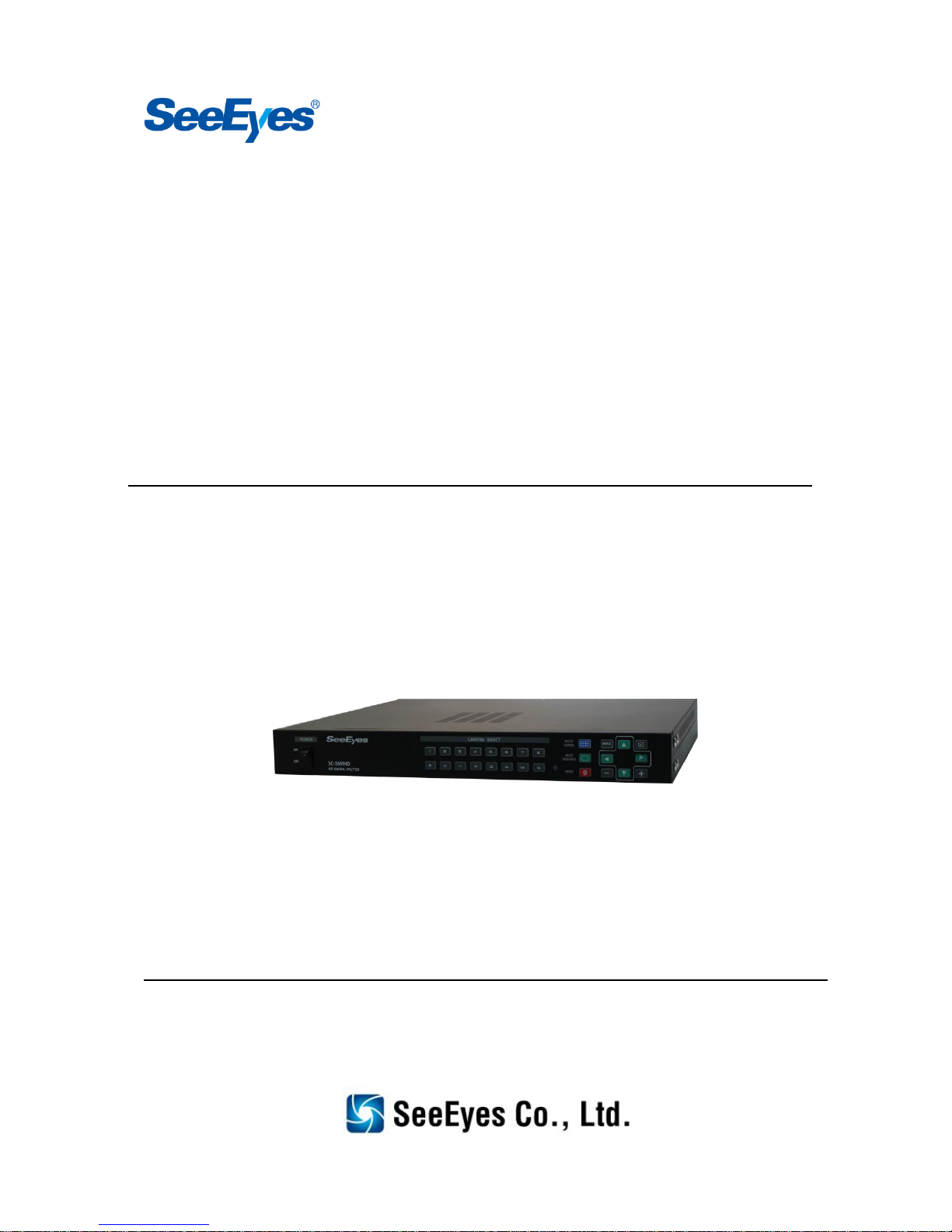
16 Channel video input HD analog splitter
SC-16MHD
User's Manual

Release Version 1.2
1
Please read this user’s manual thoroughly prior to the use this unit for its easy and convenient
use.
Caution (If you do not keep any of the below guidelines, you may get seriously
injured or cause somebody’s death)
■Please make sure to install this product after unplugging power plug. Also, do NOT use this
product by connecting many power plugs simultaneously.
- It may cause abnormal heat, fire or electric shock.
■Do NOT leave this product at any place that water falls or splashes. Also, do NOT put
anything, which is full of water such as a flower vase, on this product.
- It may cause the malfunction or fire of the product if liquid goes into it.
■Do NOT open the product case randomly, disassemble, repair or remodel this product on
your own because there is some high voltage parts.
- It may cause fire, electric shock or injury due to abnormal operation.
■Do Not install this product at a place where there is high humidity, dust or soot.
- It may cause electric shock or fire.
■Please keep the installation place clean and wipe the place with a dry towel. Also, do NOT
use water, thinner or organic solvent.
- It may cause damage on the product surface and may cause product problem or electric shock.
■Please leave this product at a cool place which does not have direct rays of the sun, keep the
temperature optimal in the installation place, and leave the installation equipment or tools
far away from where is crowded.
- It may cause fire.
■Be careful of the danger that may be caused at humid floor, ungrounded power extension
cable, worn-out power cord, lack of safety ground connection. If any problem is found,
please contact where you purchased this product.
- It may cause fire or electric shock.
■Please keep at least 15 Cm for the back of this device from the wall and keep at least 5Cm
for the sides of this device from the wall. Otherwise, the cables may be bent and/or cut due
to the narrow space between the device and the wall, and may cause malfunction or fire.
- It may cause fire, electric shock or injury.
■In case of the input voltage for the operation of this device, the voltage fluctuation must be
within 10% of the rated voltage and the power outlet must be grounded. In addition, the
power outlet for this device shall not be used for other electric heating appliances such as
hairdryers, irons, refrigerators, etc.
- It may cause abnormal overheat, fire or electric shock.
■When thundering or lightning, please unplug the power plug for your safety.
Caution (If you do not keep any of the below guidelines, you may get seriously
injured or loss of property.)
■Do NOT install this product at where is exposed to strong magnetic or radio waves (RF) and
adjacent to wireless devices such as radio or TV, etc.
■Do NOT install this product at where has too high or low temperature or humidity.
Precaution and Safety Guidelines

Release Version 1.2
2
- The appropriate temperature for this product is between 0°C and 40°C.
■Please take special care not to have this product any foreign substances inside, and do NOT
put any heavy objects on this product.
- It may cause the malfunction of this product.
■Please install this product at an well ventilated place and avoid of installing it near direct rays
of the sun or hot-air balloon.
■Do NOT install this product at where has strong shock or vibration. Otherwise, it may cause
some malfunction of this product.
■Do not use this product and please and please pull off the power plug immediately and
contact to sales shop or service center when any smoke or sound is produced from the unit.
- It may cause fire or electric shock.
■Please fix the product cover firmly and circulate air in the system operation center.
- The surrounding environment may cause the malfunction of this product.
■Please have regular product inspection at the service center to keep the good condition of
system function.
- We are not responsible for the product problem that is caused due to user’s carelessness.
■Please connect power plug to the grounded outlet.
- If you do not follow this manual, you may get electric shock or injury.
■Please put power plug at where is available to be controlled easily.
- When any trouble occurs, the power plug shall be taken off for power down.
Power cannot be shut off completely by using power button of the product only.
■When using this product adjacent to equipment which generates strong radio waves such as
radio transceivers (walkie-talkies), repeaters, it may influence video signals, cause a
malfunction of the device or some noise on the screen, or the screen may be broken, etc.
Therefore, please do not use the influencing and relevant equipment where this device is
installed and/or used.
■Please pull the power plug out when lightning strikes or it thunders.
■Transmission distance may vary, depending on coaxial cable type.
■If you need any other technical support except for things mentioned above, please do NOT
hesitate to contact our A/S center.
■Please install this item into a flat and safe place. Do not stand it vertically or put it obliquely
for use.
- It may cause the malfunction of this product or this item may fall and hurt others.
■When a coaxial cable is being extended or terminated, it should be connected in the
following way.
- BNC-M(Male) - BNC-JJ - BNC-M(Male): BNC Connector
■Please make the joint part of the cables insulated completely not to expose the metal parts.
Release Version 1.2
3
1. Introduction
1-1. Overview
SC-16MHD is a 16 channel multiformat video digital splitter, which provides high-resolution display
in various split modes in real time. This item supports various input such as AHD, TVI, CVBS and has
various output ports to be compatible with many different external devices. Also, remote control
operation is available through the RS-485 port. It displays the date, time and the name of channel on
the monitor as well as any channel loss.
1-2. Features
•Various video input (AHD, TVI, CVBS)
•Support Loop through output
•Display video of 16 channels in real time
•Various split mode: 4, 6, 8, 9, 10, 16
•Auto sequence function
•RS-485 communication port for a remote control
•Alarm port: D-SUB(26Pin) Input, 1(Relay contact) Output
•Display and save the date and time when alarm and signal loss are generated
•Various video output resolution
HDMI: 1920x1080p 50/60Hz, 1280x720p 50/60Hz, 1024x768@60Hz
VGA: 1920x1080p 50/60Hz, 1280x720p 50/60Hz, 1024x768@60Hz
CVBS: NTSC, PAL
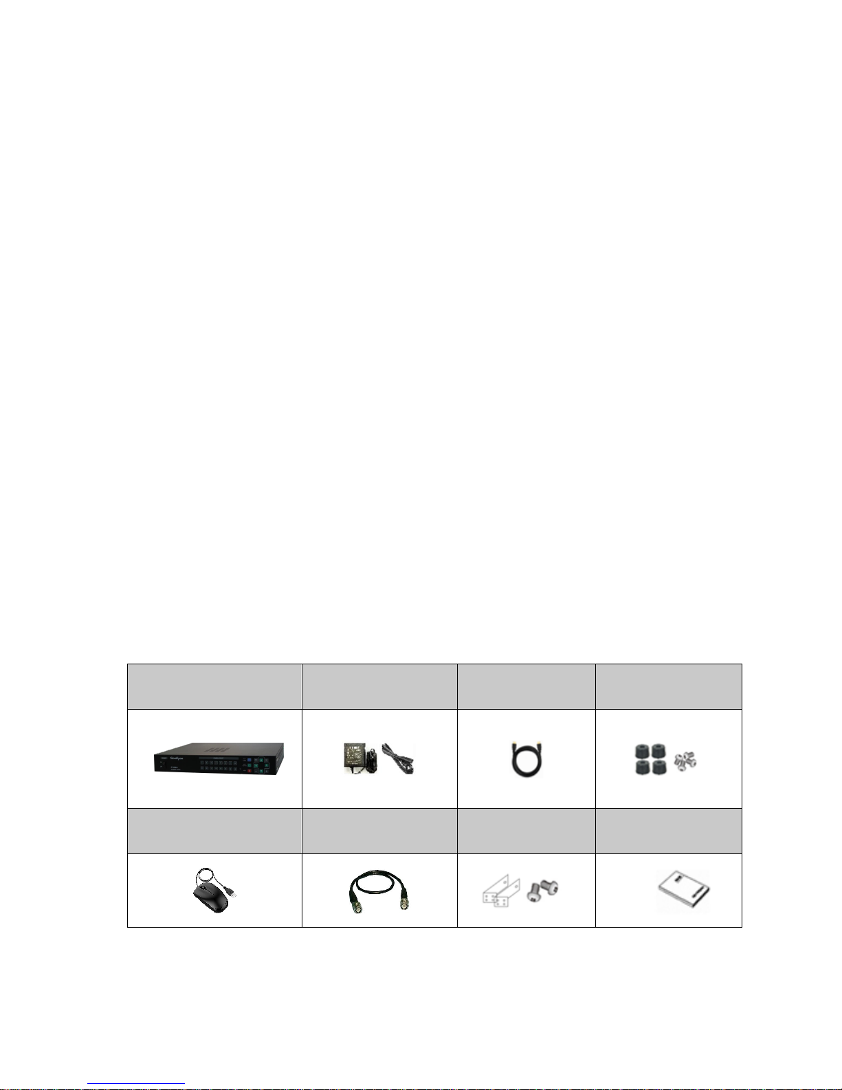
2. Components
SC-16MHD
DC 12V
Adapter
HDMI Cable
Rubber Feet
& Screw
Mouse
BNC Cable
Rack Brackets
& Screws
User’s Manual

Release Version 1.2
4
3. Product Parts and Peripheral Device Connection
3-1. Front Interface
①POWER: To turn the power on/off.
②CHANNEL DISPLAY: To display a selected channel in Full screen.
③MENU: To set up this item and/or check the current settings.
④AUTO SEQUENCE: To enable auto sequence mode.
Once you press this button, the LED will be on and the set video will be displayed successively. Once
you press other buttons in the auto sequence mode again, the auto sequence mode will be terminated
and the function related to the pressed button will start.
⑤MULTI SCREEN: To set video screen split mode. The locations of split channels can be changed in
the Setup menu.
Split Screen
Full
Quad
6 Split
8 Split
9 Split
10 Split
16 Split
⑥ESC: To terminate sub-menus in the menu.
⑦D-pad: To move to the relevant sub-menu in the menu.
⑧ENTER: To set or check sub-menu in the menu.
⑨MINUS: To go to the previous channel or channels (available in split mode as well)
e.g.) When pressing this button in quad screen of 5CH, 6CH, 7CH and 8CH, the screen will be changed
to the quad screen of 1CH, 2CH, 3CH and 4CH.
⑩PLUS: To go to the next channel or channels (available in split mode as well)
e.g.) When pressing this button in quad screen of 5CH, 6CH, 7CH and 8CH, the screen will be changed
to the quad screen of 9CH, 10CH, 11CH and 12CH.

Release Version 1.2
5
3-2. Backside Interface
①VIDEO OUTPUT: Looped through output (AHD, TVI, CVBS).
②VIDEO INPUT: HD Analog (AHD, TVI) and CVBS video input (up to 16 channels).
③CVBS OUT: CVBS video output.
④VGA: VGA output.s
⑤ALARM IN: Alarm input.
⑥HDMI: HDMI output.
⑦USB: To connect with a mouse.
⑧ALARM OUT: Relay contact output.
- To operate a light or an emergency bell by using electric signal when any alarm occurs.
- N.O: Normal Open: The contact point is off. (Default setting)
- N.C: Normal Close: The contact point is on.
* Please refer to the ‘5-4. Alarm Input’ and/or ‘5-5. Alarm Output’ for more information of alarm.
⑨DC 12V IN:Power input.
⑩RS-485: RS-485 communication by an external device for a remote control. (e.g. PTZ camera)
Release Version 1.2
6
4. Menu Setup
4-1.SYSTEM
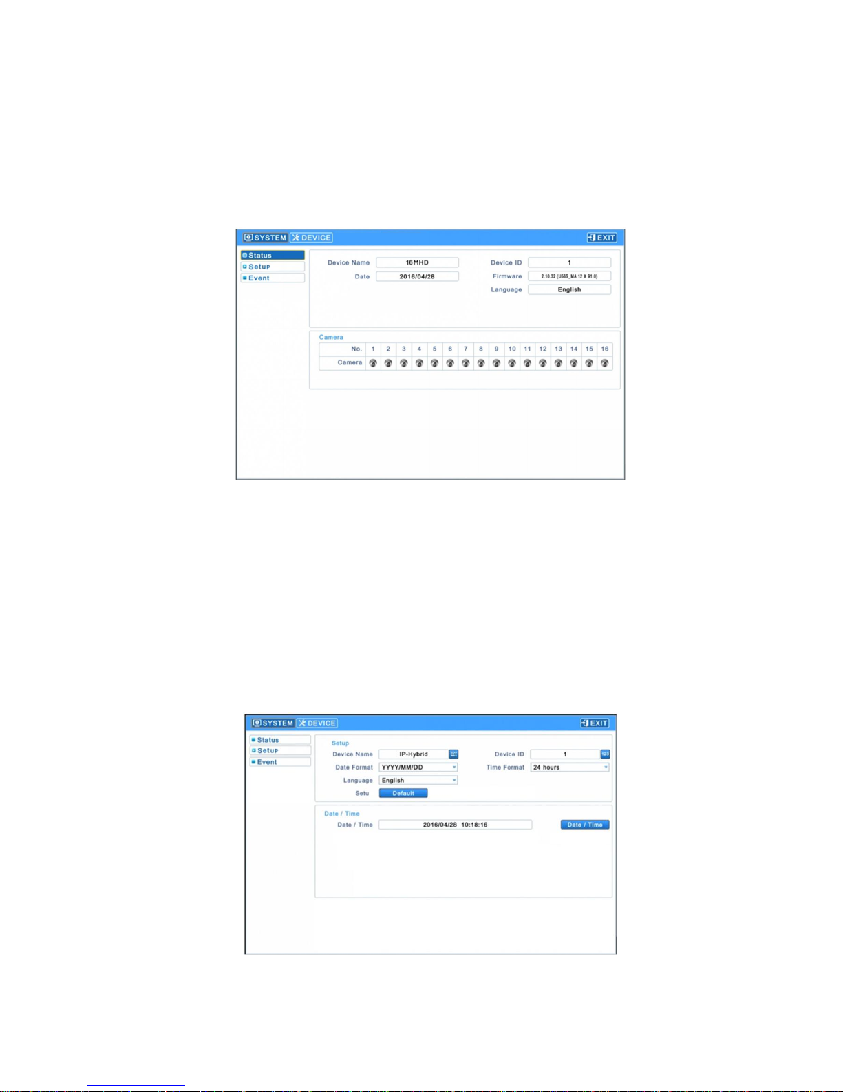
4-1-1. Status
▶Use a mouse for the menu settings.
▶Enter the Setup menu to show the following screen.
- Device Name
- Device ID
- Date
- Firmware (Firmware version)
- Language (Language settings)
- Camera (Camera status)
4-1-2. Set up
▶Enter [System] →[Set up] to show the following screen.
Release Version 1.2
7
4-1-2-1. Set up
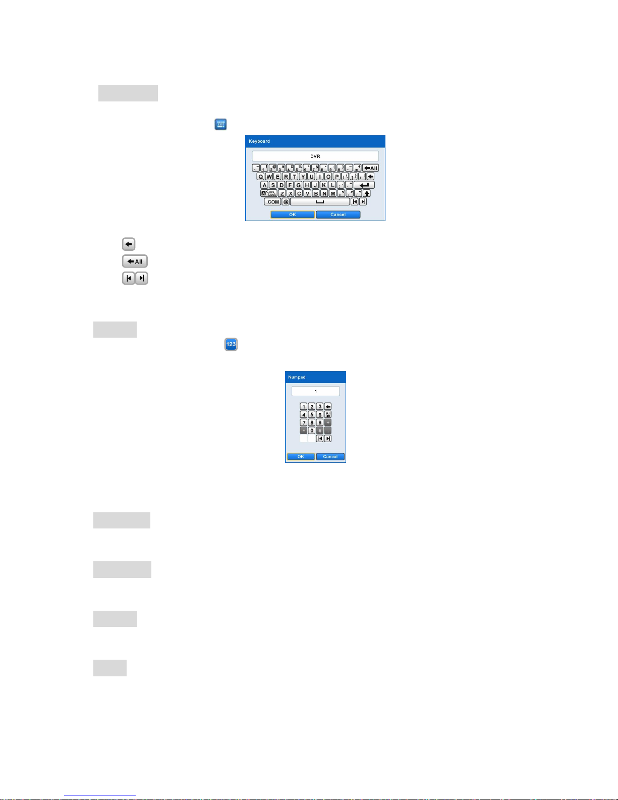
Device Name
- Set up the device name.
- Click the keyboard icon( ) on the right side to display the following keyboard on the screen.
- Enter a device name by using the above keyboard popped up.
①: To delete letters/words from the right end of the entered device name.
②: To delete all letters/words of the entered device name.
③: To move the cursor.
- Click ‘OK’to save the entered device name. Click ‘Cancel’ not to save the entered device name.
Device ID
- Click the numeric pad icon( ) on the right side to display the following numeric pad on the
screen and use it for RS-485 related device ID settings.
- Enter any number from 1 to 255 to set up RS-485 device ID.
- Click ‘OK’ to save the entered device ID and click ‘Cancel’ not to save the entered values.
Date Format
- Set up the way of the displayed date.
Time Format
- Set up the way of the displayed time.
Language
- Set up the language.
Default
- Reset this device to the factory default settings.

Release Version 1.2
8
4-1-2-2. Date / Time
- Click the date and time menu ( ) to see the calendar as follows.
- Set up the date (year/ month/ day) by using following arrow keys.
∙: To change the year.
∙: To change the month.
∙The selected date will be shown in blue.
- Set the time by selecting the time section.
∙Any selected item(AM/PM, Hour, Minute, Second) will be marked in blue.
∙Change numbers by clicking ▲, ▼buttons on the right side.
- Click ‘OK’ to save the setting values and click ‘Cancel’ not to save them.
4-1-2-3. Firmware
- Indicate this splitter’s software version.
4-1-3. Event
▶Enter [System] →[Event] to show the following screen.
- Event items are as follows:
∙System Start
∙System Reboot
∙Setup Default/Imported/Exported
∙Resolution Changed
∙Video out Changed
∙Time Adjust Before/After
∙Setup Enter/Exit
∙Video Loss Occurred

Release Version 1.2
9
4-2. DEVICE
4-2-1. DISPLAY
▶Enter [Device] →[Display] to show the following screen.
4-2-1-1. General
- Set video output resolutions.
- Set the CVBS video to NTSC, PAL or AUTO.
- The default setting is ‘AUTO’.
- Reboot this splitter after changing the settings to recognize the video signal again.
- Transparency setting values are adjustable by +, - buttons on OSD menu.
Video Output
- Select video output (Main Screen, Spot)
- Click ‘Apply’ on the right side to complete the setup.
- Reboot this splitter after changing the settings to recognize the video signal again.
* Some LEDs on the front interface may not be turned on when rebooting, and after completing its
reboot, the LED will be working properly.

Release Version 1.2
10
4-2-1-2. OSD Icon
▶Enter [Display] →[OSD Icon] to show the following screen.
- Select which items will be shown on the screen (OSD).
- Reset it to the factory default settings by clicking ‘Default’ on the right side.
- Adjust the position of OSD icons by the OSD position options at the bottom.
∙Horizontal: Set the horizontal interval of OSD icons (Range: 0~50). Bigger number means more
interval.
∙Vertical: Set the vertical interval of OSD icons (Range: 0~50). Bigger number means more
interval.
∙Adjust the range by using ▲, ▼buttons.
4-2-1-3. Menu Icon
▶Enter [Display] →[Menu Icon] to show the following screen.
- Select which items will be shown on the screen (Icons that will be shown on the left/right sides)
- Click ‘All’ to select or not to select all sub-items.
- Reset it to the factory default settings by clicking ‘Default’ on the right side.
Release Version 1.2
11
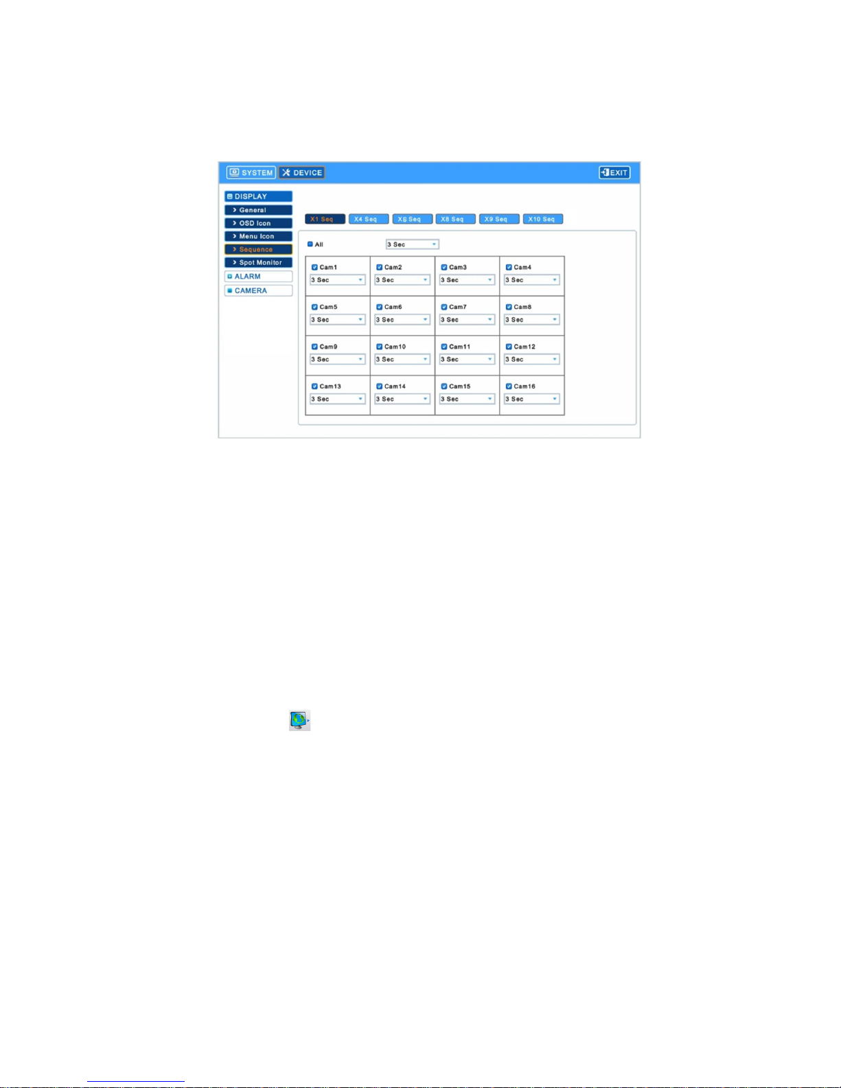
4-2-1-4. Sequence
▶Enter [Display] →[Sequence] to show the following screen.
- Select the channels to be in Auto Sequence mode and set the display switching time.
∙X1 Seq: Set the display switching time in Full screen.
∙X4 Seq: Set the display switching time in Quad screen.
∙X6 Seq: Set the display switching time in 6-split screen.
∙X8 Seq: Set the display switching time in 8-split screen.
∙X9 Seq: Set the display switching time in 9-split screen.
∙X10 Seq: Set the display switching time in 10-split screen.
- Select() the cameras to be added into Auto Sequence mode. Non-selected cameras will not be in
the Auto Sequence mode.
- Set up the display switching time among 3, 5, 10, 15, 30, 60 seconds in the list.
- Click ‘All’ to set up the display switching time for every camera at once.
- Click the sequence icon( ) on the OSD menu by a mouse or press the Auto Sequence button
on the front interface after closing the setup menu and changing the split mode.
- Available to set each camera video to the position where a user prefers in X4, X6, X8, X9, X10 Seq
modes.
Release Version 1.2
12
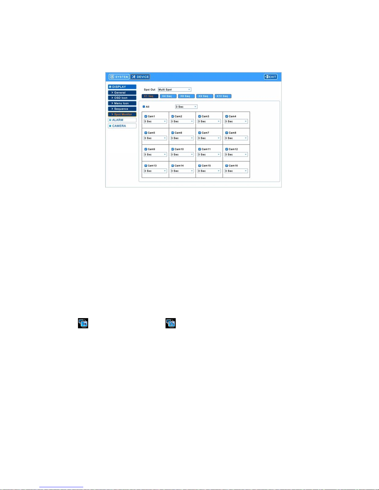
4-2-1-5. Spot Monitor
▶Enter [Display] →[Spot Monitor] to show the following screen.
- Select the channels to be in Auto Sequence mode of Spot monitor and set the display switching
time
∙X1 Seq: Set the display switching time in Full screen.
∙X4 Seq: Set the display switching time in Quad screen.
∙X8 Seq: Set the display switching time in 8-split screen.
∙X9 Seq: Set the display switching time in 9-split screen.
∙X10 Seq: Set the display switching time in 10-split screen.
- Select() the cameras to be added in to the Spot monitor’s Auto Sequence mode. Non-selected
cameras will be eliminated from the sequence mode.
- Set up the display switching time among 3, 5, 10, 15, 30, 60 seconds in the camera list.
- Click ‘All’ to set up the display switching for every camera at once.
- Close the setup menu, move the mouse cursor to the left side and click the Spot Out split mode
icon ( ) or Spot Out Sequence icon( ) to start the mode in demand for SPOT.
- Available to set each camera video to the position where a user prefers in X4, X8, X9, X10 Seq
modes.
Release Version 1.2
13
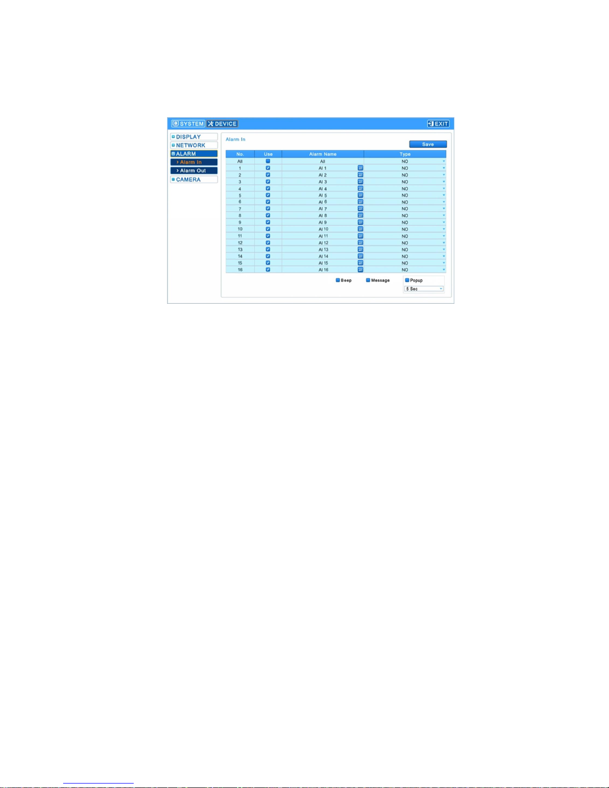
4-2-2. ALARM
▶Enter [Device] →[Alarm] to show the following screen.
4-2-2-1. Alarm-In
- Select alarm names and types in this menu.
- Click the keyboard icon in the ‘Alarm-in’ menu to show the keyboard and enter the name.
- Available to set specific channels for Alarm input. Select() the relevant channels in the ‘Use’ items
shown right left to each alarm name. If you do not use any specific channel’s ‘Alarm In’ function,
please do not mark(□) there.
- Click ‘All’ to change every alarm type at once.
∙NO(Normally Open): The contact sensor is open (Factory default setting).
∙NC(Normally Closed): The contact sensor is closed.
- Available to set up the event when generating an alarm by the menus at the right bottom.
∙Beep: Buzzer out when an alarm is generated.
∙Message: An alarm message pops up and stay on the screen for around 30 seconds when an
alarm is generated.
∙Popup: The relevant channel’s video pops up and stay on the screen for 5, 10, 30 seconds or
keep being shown on the screen in Full Screen mode, when an alarm is generated.

Release Version 1.2
14
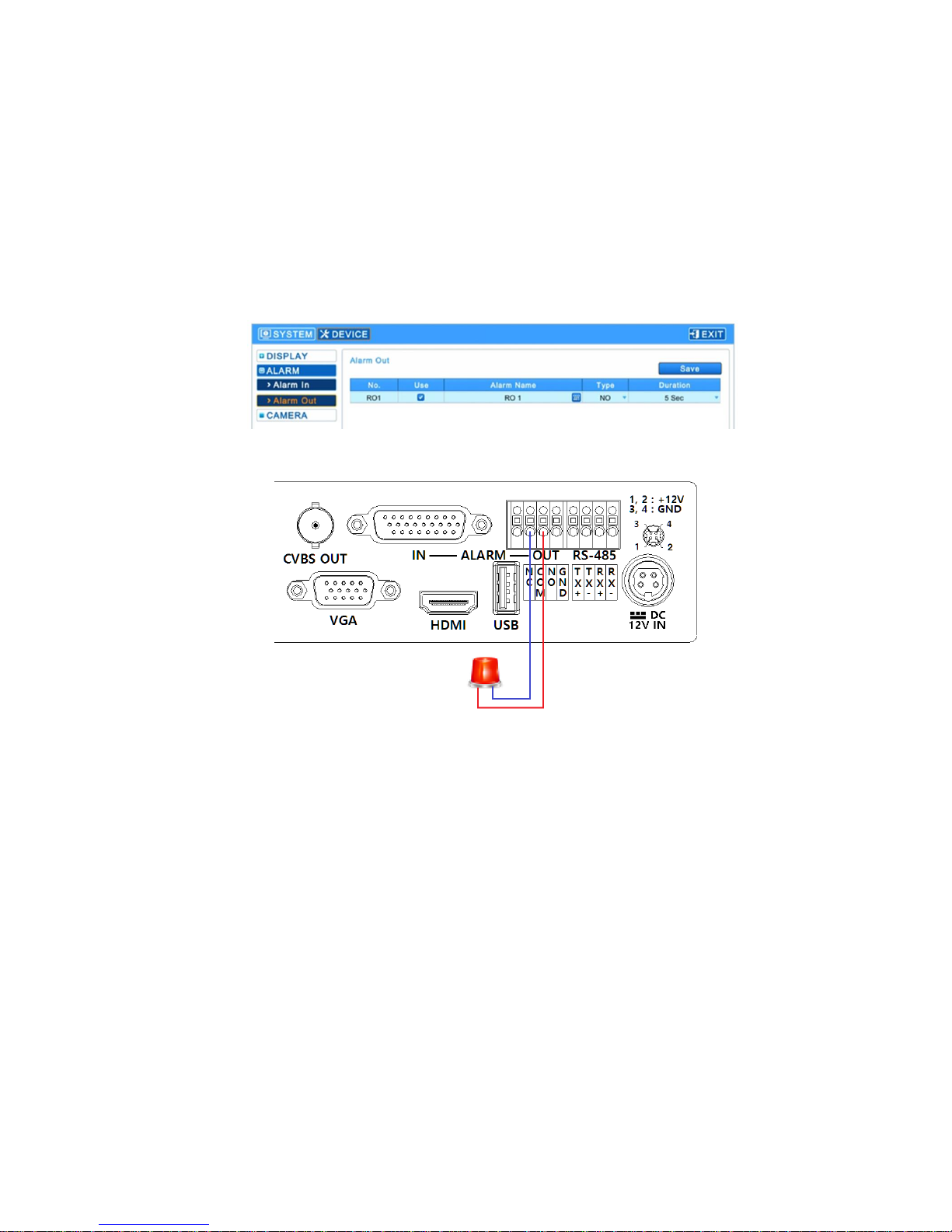
4-2-2-2. Alarm-Out
▶Enter [Alarm] →[Alarm-Out] to show the following screen.
- Select alarm names and types in this menu.
- Click the keyboard icon in the ‘Alarm-in’ menu to show the keyboard and enter the name.
- Select types of alarm out in the ‘Type’ item.
∙NO(Normally Open): Relay signal output when the contact sensor is open (Factory default
setting)
∙NC(Normally Closed): Relay signal output when the contact sensor is closed.
- Available to change the operating time or period of Alarm Out in the Duration item.
Release Version 1.2
15
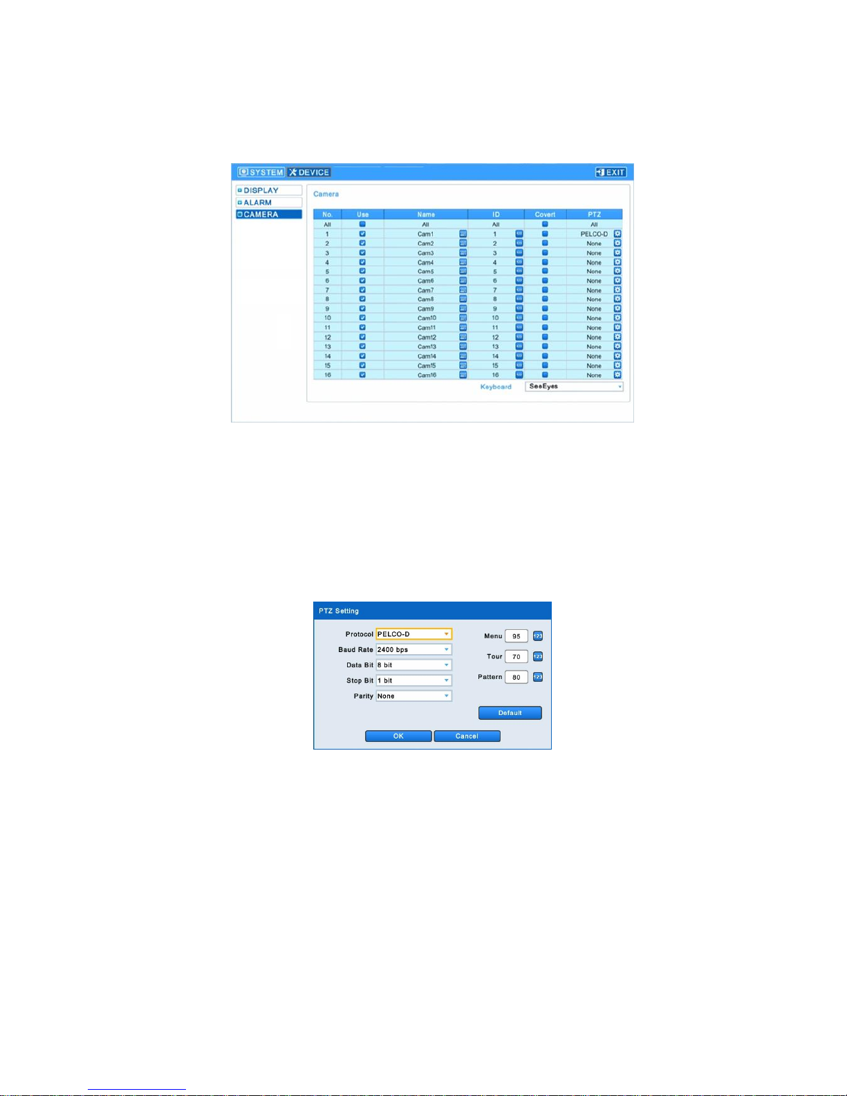
4-2-3. CAMERA
▶Available to contact a PTZ camera when connecting your PTZ camera to the RS-485 Tx. terminal.
▶Enter [Device] →[Camera] to show the following screen.
- Click the keyboard icon in each ‘Name’ menu to show the keyboard and enter each camera name.
- Click the number icon in each ‘ID’ menu to show the numeric pad and set up each camera’s ID
(0~9999).
- Select any checkbox in the ‘Covert’ menu to hide the selected part from the monitor screen.
Click ‘All’ to select or hide all at once.
- Select any specific camera in ‘PTZ’ menu to change the PTZ setting of the selected camera and
show the following on the screen.
∙Set up Protocol / Baud Rate / Date Bit/ Stop Bit/ Parity.
∙Set up a PTZ camera’s menu in the Menu, Tour, Pattern menus.
> If the OSD entry value is 95 + PSET, please set the Menu to 95.
> If the Tour shortcut value is 71~79 + PSET, please set the Tour to 70.
> If the Pattern shortcut value is 81~89 + PSET, please set the Pattern to 80.
> Please refer to the PTZ camera’s instructions for more details of its settings.
∙Reset it to the factory default settings by clicking ‘Default’ button.
∙Click ‘OK’ to save the setting values and click ‘Cancel’ not to save them.
Release Version 1.2
16
5. Operation
5-1. Functions of the Mouse
Press the right button of the mouse to who the following menus.
Key Name
Functions
Color
Set up specific channel’s brightness/ darkness/ chroma values
PTZ
Activate or deactivate PTZ control function
PIP
Picture in Picture function
Position
Change the position of camera video
5-2. Display Mode
▶The available display mode for the main monitor is Full screen mode, Split screen mode, Channel
Auto Sequence mode, PIP mode.
- Full screen: Press the relevant channel number key on the front interface to turn to the channel in
Full screen. If you use a mouse, please double-click the relevant channel to turn the
video to Full screen and double-click it again to go back to the previous split mode.
- Split screen: Press the ‘MULTI SCREEN’ on the front interface or click ‘ ‘ icon to turn to split
screen.
- Auto sequence: Press the ‘AUTO SEQUENCE’ key on the front interface or click ‘ ‘ icon to set
up Auto Sequence mode.
5-3. Digital Zoom
- Select the channel to display in Full screen mode.
- Press the left button of the mouse and drag out the part to zoom in.
- Click the left button of the mouse twice to release the zoom in.
- The digital zoom-in function is available in Full screen mode only, so please do not use this
function in split screen, auto sequence mode and PIP mode.
5-4. Alarm-In functions
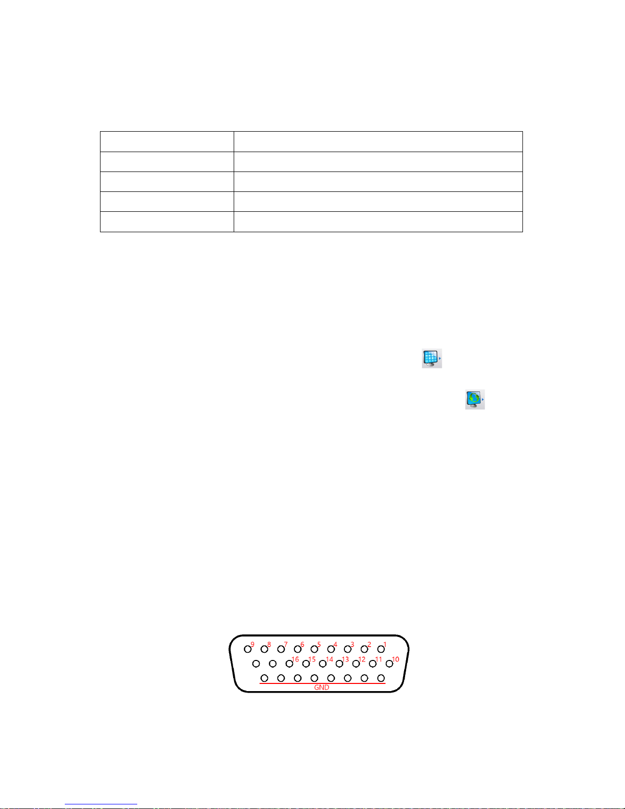
5-4-1. Alarm-In Port
▶The Alarm-In input port consist of D-SUB 26Pin(Female) connector and the channels of this pin
are as follows.
※The relevant video channel screen will be shown when the alarm input.
※‘Alarm-In’ OFF =”0”, ‘Alarm-In’ ON =”1” (GND and input signal are shorted out)
※‘Alarm-In’ is deactivated for loss channels.
Release Version 1.2
17
5-4-2. Alarm-In Operation
▶Connect the relevant channel’s alarm signal line(contact signal, which does not have electric signal)
and GND line.
5-5. Alarm-Out function
5-5-1. Alarm-Out port
- Connect the signal port to COM port and NC or NO..
Example for Alarm-Out
Release Version 1.2
18
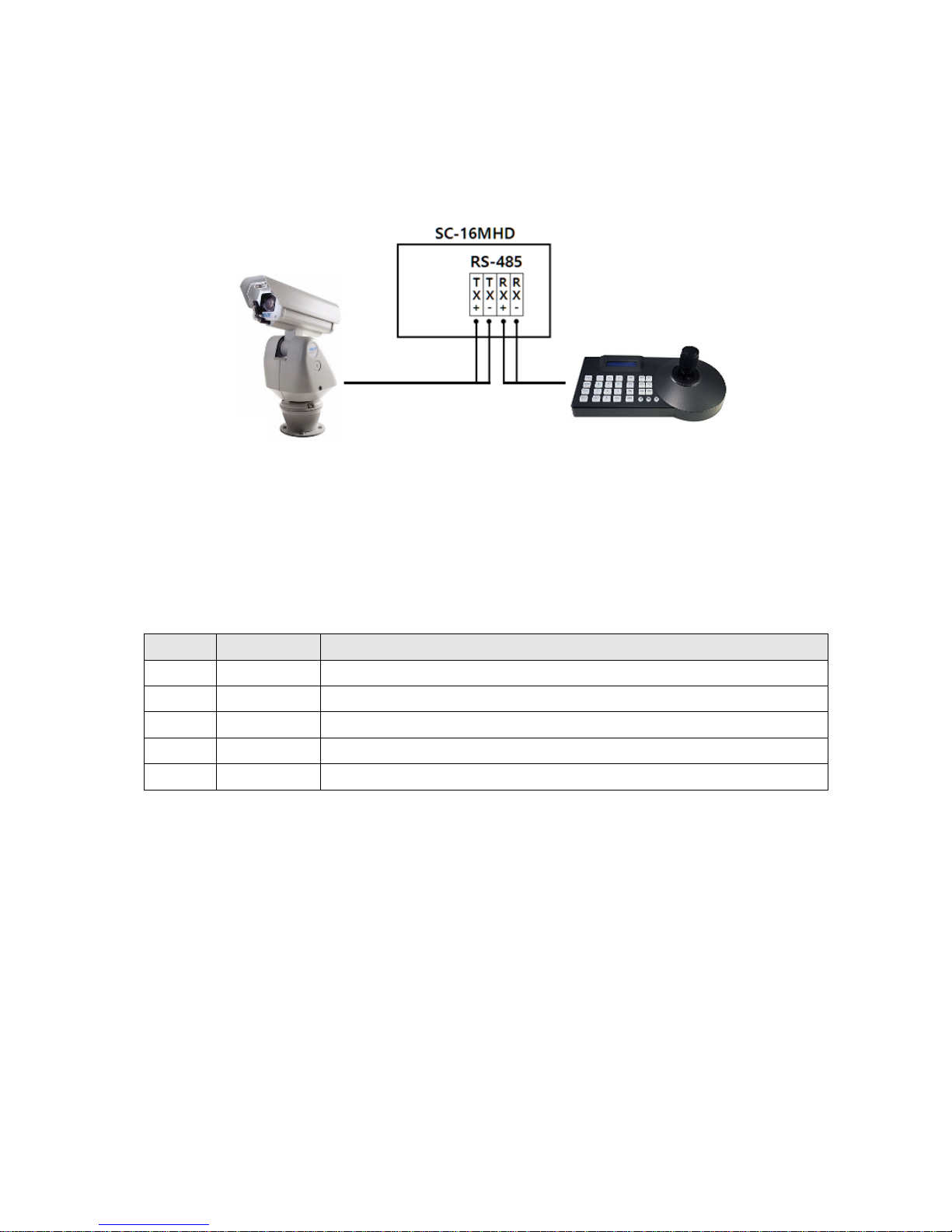
5-6. RS-485
5-6-1. Connection Method
▶Refer to the ‘4-2-3. CAMERA’ for more information on camera settings.
5-6-2. Control communication data format
▶Set up the split screen or others by a RS-485 controller in remote distance.
- Data Length: 8 Bit, Start/Stop Bit: 1Bit, Parity Bit: None, Baud Rate: 9600
Byte
Value
Function
1
0xA0
STX (Launching data)
2
0x16
Device Code
3
0x01 ~ 0xFF
Address (Device ID)
4
Data Byte
Control Data
5
Check Sum
Check Sum = Byte2 + Byte3 + Byte4

Release Version 1.2
19
5-6-3. RS-485 Control Data Code
Hex
Function
Packet
30
1CH Full Display
0XA0 0X16 0X01 0X30 0X47
31
2CH Full Display
0XA0 0X16 0X01 0X31 0X48
32
3CH Full Display
0XA0 0X16 0X01 0X32 0X49
33
4CH Full Display
0XA0 0X16 0X01 0X33 0X4A
34
5CH Full Display
0XA0 0X16 0X01 0X34 0X4B
35
6CH Full Display
0XA0 0X16 0X01 0X35 0X4C
36
7CH Full Display
0XA0 0X16 0X01 0X36 0X4D
37
8CH Full Display
0XA0 0X16 0X01 0X37 0X4E
38
9CH Full Display
0XA0 0X16 0X01 0X38 0X4F
39
10CH Full Display
0XA0 0X16 0X01 0X39 0X50
41
11CH Full Display
0XA0 0X16 0X01 0X41 0X58
42
12CH Full Display
0XA0 0X16 0X01 0X42 0X59
43
13CH Full Display
0XA0 0X16 0X01 0X43 0X5A
44
14CH Full Display
0XA0 0X16 0X01 0X44 0X5B
45
15CH Full Display
0XA0 0X16 0X01 0X45 0X5C
46
16CH Full Display
0XA0 0X16 0X01 0X46 0X5D
47
Multi screen
0XA0 0X16 0X01 0X47 0X5E
48
Menu
0XA0 0X16 0X01 0X48 0X5F
49
Enter
0XA0 0X16 0X01 0X49 0X60
4A
ESC
0XA0 0X16 0X01 0X4A 0X61
50
4-Split Display
0XA0 0X16 0X01 0X50 0X67
56
6-Split Display
0XA0 0X16 0X01 0X56 0X6D
51
8-Split Display
0XA0 0X16 0X01 0X51 0X68
52
9-Split Display
0XA0 0X16 0X01 0X52 0X69
53
10-Split Display
0XA0 0X16 0X01 0X53 0X6A
55
16-Split Display
0XA0 0X16 0X01 0X55 0X6C
5A
Auto Sequence
0XA0 0X16 0X01 0X5A 0X71
64
Down
0XA0 0X16 0X01 0X64 0X7A
6C
Left
0XA0 0X16 0X01 0X6C 0X83
72
Right
0XA0 0X16 0X01 0X72 0X89
75
Up
0XA0 0X16 0X01 0X75 0X8C
6D
-(Minus)
0XA0 0X16 0X01 0X6D 0X84
70
+(Plus)
0XA0 0X16 0X01 0X70 0X87
Table of contents
Other SeeEyes Media Converter manuals

SeeEyes
SeeEyes SC-HDR01S User manual

SeeEyes
SeeEyes SC-IPH3002DC User manual

SeeEyes
SeeEyes SC-90DS User manual

SeeEyes
SeeEyes SC-MHC01 User manual

SeeEyes
SeeEyes SC-MAC02 User manual

SeeEyes
SeeEyes SC-HDT0801S User manual

SeeEyes
SeeEyes SC-SDHD01 User manual

SeeEyes
SeeEyes SC-MA8VDA User manual

SeeEyes
SeeEyes SC-40DQH User manual

SeeEyes
SeeEyes SC-HMC16E User manual


