SeeEyes SC-IPH3002DC User manual

Release Version 1.0
PoE ALL IN ONE(Injector & Extender & Splitter)
SC-IPH3002DC
User’s Manual
SC-IPH3002DC

Release Version 1.0
1
Precaution and Safety Guidelines
The content of this guideline is to protect the safety of users and prevent property damage.
Please be sure to read this user’s manual thoroughly and use the device correctly.
Warning (If you do not keep any of the below guidelines, you may get seriously injured
or cause somebody’s death.)
■Be sure to install the product after unplugging power cord. Also, do not use many power
plugs at the same time.
- It may cause abnormal heat, fire and electric shock.
■Do not leave the device at any place that water falls or splashes. Also, do not put anything
full of water such as a flower vase on the device.
- It may cause malfunction or fire if liquid goes into the device
■Do not open the lid arbitrarily as this device has high voltage part inside. Never disassemble,
repair or modify it.
- By abnormal working, it may cause fire, electric shock and personal injury.
■Do not install this product in places with high humidity, dust, or soot.
- It may cause electric shock and fire.
■Always keep the location of the appliance clean during or after installation to prevent dust.
Especially when cleaning the device, wipe it with dry towel and do not use water, thinner or
organic solvent.
- It may cause damage to the surface of the device, malfunction or electric shock.
■Keep the device in a cool place where doesn’t let direct sunlight. Keep it at a proper
temperature and avoid heating appliances like candle or heater. Also, keep the equipment or
tools away from places where people come and go.
- It may cause fire.
■Pay attention to possible hazards in the workplace, such as wet floor, ungrounded power
extension cables, old power cords and a lack of safety earth. Consult your place of purchase or
professional if problems arise.
- It may cause fire and electric shock.
■Concerning the input voltage for operating this device, a voltage range must be within 10%
of rated voltage. Also, do not use a heat source such as a hair dryer, iron and refrigerator to the
same power unit.
- It may cause abnormal heat, fire and electric shock.
■Disconnect the power plug with care during thunder and lightning.
■Do not bend the power cord by excessive force. Make sure the power cord is not crushed by
heavy things.
- It may cause fire.
■Install the cable as “U” shape in order to prevent rain water/dew/fog, etc. from falling
through the cable.

Release Version 1.0
2
Caution (If you do not keep any of the below guidelines, you may get injured or suffer
property loss.
■Avoid installing near strong magnetic fields or radio waves and wireless devices such as radio
or TV.
- Install in a place that is free from magnetic, radio, or excessive vibration.
■Proper ambient temperature and humidity are recommended.
- Avoid extremely high temperatures(over 50°C) or low(below -10°C), and humid conditions.
■Do not place heavy items on the product or let foreign substances enter inside the device.
- It may cause failure.
■Install in well ventilated place, and avoid direct sunlight or heat appliance.
■Strong shock or vibration may cause device failure. Be careful when using the device.
- Install in a place without severe vibration.
■If you notice any unusual noise or smell, unplug the power supply immediately and contact
the place of purchase or service center.
- There may be a risk of fire and electric shock.
■Rotate the air properly in the system operating room and secure the cover of the main body.
- It may be the cause of failure by environmental factors.
■Refer the device to the service center and get regular checkup to maintain the performance
of the system.
- We are not responsible for any damages caused by user’s carelessness.
■Be sure to plug the power cord with grounded outlet.
- There is a risk of electrical shock and personal injury.
■Place the power plug in a location that is easy to operate.
- If a failure of the product occurred, the power plug must be unplugged to power down
completely. The power button on the main body does not completely disconnect power.
■Do not use this device in close proximity to a device that produces strong waves such as
radio set(TRANCEIVER, Walkie-talkie, etc.) or repeater. It may affect HD-SDI and EX-SDI signal,
or cause disorders such as noise or crack on the screen.
■The transmission medium(CABLE) must be a UTP(CAT.5e) cable.
■Be careful not to change the cable configuration during installation. (Refer to ‘4. CABLE PIN
Configuration’ on page 5.)
■This product’s CAMERA PORT has a maximum output power of 30W and the EXTENSION
PORT has a maximum output power of 30W. Please check the output power of each port when
connecting a camera or more than two product in series.
- The supply power is limited by the camera’s power consumption, transmission distance and cable loop
resistance, and may affect other channels.
■UTP(Unshielded Twisted Pair) Cable is for indoor use only. Use a STP(Shield Twisted Pair)
Cable which is covered for outdoor use.
■Transmission distance may vary depending on the type of UTP cable.
■Refer to the user’s manual for problems or questions besides the above. Contact our service
center if you need assistance from a professional technician.

Release Version 1.0
3
1. Introduction
1-1. Overview
SC-IPH3002DC is an all-in-one product that combines PoE injector/extender/splitter functions and can
be used in various network construction environments. In addition, the Ethernet data transmission
distance can be extended by using the Ethernet bandwidth adjustment switch of the product, and it
is a suitable product to save construction costs by supplying power to peripheral devices using DC
power input using the PoE splitter function.
1-2. Features
•Support Ethernet injector function
•Ethernet extender function support
•PoE splitter function supported (DC 12V Max. 1A Output)
•Transmission distance can be extended by changing the bandwidth switch setting value
(100Mbps/10Mbps).
100Mbps switch setting: transmission possible up to 100m (based on CAT.5e)
10Mbps switch setting: transmission possible up to 250m (based on CAT.5e)
•Power input method: DC 48~56V Adapter or PoE (DC Adapter power supply priority)
•Auto MDI/MDIX function support
•Built-in surge protection circuit
2. Components
SC-IPH3002DC
User’s Manual
Adapter(DC 48V, 1.0A),
(Optional)
※The accessories included in the package may be changed.
Release Version 1.0
4
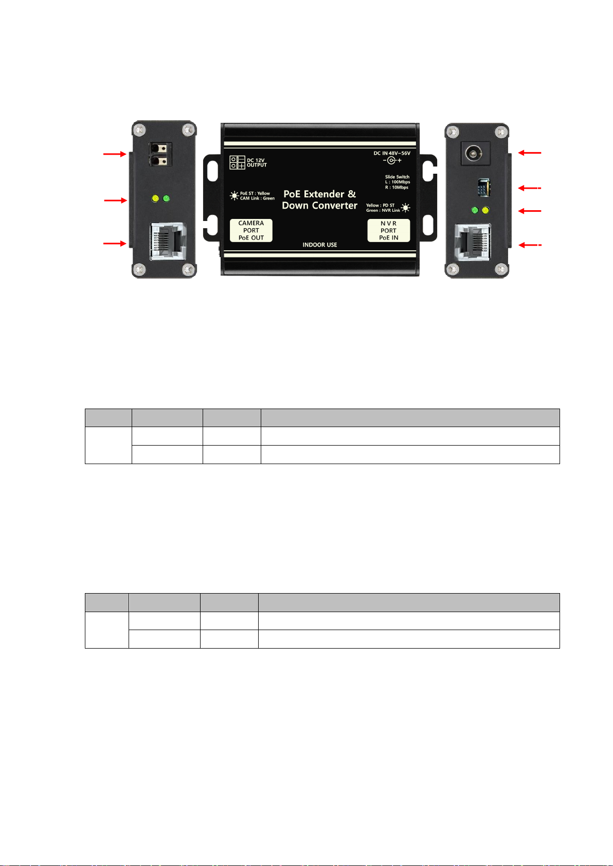
3. Product Parts & Functions
①DC12V Output : DC 12V power output terminal (Max. 1.0A)
※When connecting the power output cable, pay attention to the polarity.
②Camera Port LED : Camera Port Link LED, PoE Output Status LED
< LED status indication >
③Camera Port : RJ-45 connector for IP Camera connection
- Endspan PoE function (Mode A) supported. (IEEE802.3 AF/AT)
④NVR Port : RJ-45 connector for NVR or PoE Switch HUB connection
- PoE Mode A, B support. (IEEE802.3 at type-2)
⑤NVR Port LED: NVR Port Link LED, PoE Input Status LED
<LED status indication >
⑥Slide Switch: Slide switch for bandwidth setting
⑦DC IN 48V ~ 56V: DC adapter 48V to 56V power input terminal
※When the PoE power supplied to the NVR PORT is insufficient, connect an external adapter to
use it.
LED Color
Status
Description
Camera
Port
Yellow
On/Off
On for PoE output
Green
Off/Blink
Camera Port Data Link 시Blink
LED Color
Status
Description
NVR
Port
Yellow
On/Off
On for PoE input
Green
Off/Blink
NVR Port Data Link 시Blink
⑦
①
⑤
②
③
④
⑥
Release Version 1.0
5
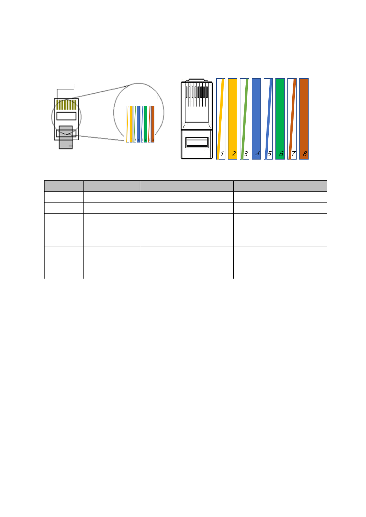
4. CABLE PIN arrangement (TIA / EIA 568B method)
No.
Color
Color
Function
1
Orange + White
White
Orange
TX+
2
Orange
Orange
TX-
3
Green + White
White
Green
RX+
4
Blue
Blue
PWR+
5
Blue + White
White
Blue
PWR+
6
Green
Green
RX-
7
Brown + White
White
Brown
PWR-
8
Brown
Brown
PWR-
co
pp
er
co
nn
ect
io
nc
op
pe
r
co
nn
ec
op
pe
r
co
nn
ect
io
nc
tio
n

Release Version 1.0
6
5. Connection Diagrams
5-1. IPH3002DC application case 1 (when using LED signage to notify CCTV
installation)
5-2. IPH3002DC application case 2 (when configuring an emergency call system)
5-3. IPH3002DC application case 3 (when configuring a wireless bridge system)
※Additional power supply may be required depending on camera power consumption.
※Please design a separate network for general communication (Internet/in-house, etc.) and
CCTV network.
IR floodlight
LED billboard
IP Camera
PoE switch
PoE Passive Injector
Warning
light
SC-ECS30CWP
(IP Emergency bell)
PoE Passive Injector
PoE switch
Wireless bridge
PoE Passive Injector
PoE switch
or

Release Version 1.0
7
5-4. IPH3002DC Power available by distance
Cable type
Tx to Rx Distance (m/km)
100m
250m
CAT.5e
Bandwidth (TCP)
100Mbps
10Mbps
Loop resistance (Ω)
9.5Ω
23.75Ω
Available power (W)
DC48V(IEEE802.3 af)
~14W
~11W
DC12V Output
Max. 6W
Max. 6W
DC56V(IEEE802.3 at)
~20W
~17.6W
DC12V Output
Max. 12W
Max. 12W
※PoE camera recommended power consumption table may change depending on camera
and cable type
※Power consumption table may change depending on PoE switch hub performance
※When connecting a camera with high consumption current or high inrush current, use a DC
56V adapter or apply PoE+ power to the product.
※When using as a simple switch hub, it can be used after external power is applied.
※If you cross cables between the Camera PORT and NVR PORT terminals, power may not be
supplied and video may not be output.

Release Version 1.0
8
6. Troubleshooting method
Condition
Check Method
Power is not
supplied.
•Check the power cable connection state.
•Check if the exclusive adapter is used.
•Check the PoE switch hub connection state.
•Check the CABLE PIN configuration state.
•Check if the connection to EXTENSION PORT and NVR PORT are
correct.
Video is not
displayed.
•Check the CABLE PIN configuration state.
•Check the cable transmission distance.
•Check the ground state.
•Check if the camera model is able to input PoE.
•Check if the camera is compatible with NVR.
•Check if the connection to EXTENSION PORT and NVR PORT are
correct.
Video status is
uneven.
•Check the CABLE PIN configuration state.
•Check the cable transmission distance.
•Check the ground state of the product.
•Check the set value of camera.
(Transmission video quality, frame rate, resolution, etc.)
•Check if the bandwidth is over 10Mbps after setting Bandwidth
Switch as 10M.
Network connection
state is abnormal.
•Check the NETWORK CABLE configuration.
•Check if there is any equipment that generates radio or strong
waves in the surrounding environment.
•Check if the Network configuration is installed properly.

Release Version 1.0
9
7. Specifications
Model No.
SC-IPH3002DC
Power
Input
DC Power
DC 48V 또는 DC 56V Adaptor
PoE Power
PoE IEEE 802.3af / 802.3at, Endspan / Midspan (Mode A / Mode B)
Feature
Power input DC Adaptor and DC Adapter power supply priority
among PoE
PoE Output
CAMERA PORT
Max 30W, Standard PoE Support, IEEE802.3 af/at Mode A
Power Consumption
Max 1W (No-load Condition)
Max. Transmission Distance
When setting 100Mbps: Max. based on CAT.5e. 100m
When setting 10Mbps: Max. 250m
Connection
Port
NVR PORT
RJ-45 1Port (TIA/EIA568B Type)
CAMERA PORT
RJ-45 1Port (TIA/EIA568B Type)
POWER
DC JACK
RJ-45 Connector
Pin Assignment(Polarity)
1Pin: TX(+), PWR(+) 2Pin: TX(-), PWR(+)
3Pin: RX(+), PWR(-) 6Pin: RX(-), PWR(-)
LED
Indicator
Camera
Side
Yellow
On for PoE output
Green
Camera Port Data Link 시Blink
NVR
Side
Yellow
On for PoE input
Green
NVR Port Data Link 시Blink
Slide switch
change the transmission bandwidth (100Mbps , 10Mbps)
Transmission Bandwidth
10/100Mbps support (Full duplex)
Operating Temperature /
Operating Humidity
-10°C ~ +50°C / 0 ~ 80%
Material / Weight
aluminum / 104g
Dimensions
77(W) x 60(H) x 25(D)mm
※Using a LAN cable extension gender (coupler) causes signal attenuation. The use of multiple
extended gender connections is not recommended.
※Cable transmission distance may vary depending on camera and NVR specifications.
※When using the camera PoE function, the transmission distance may vary depending on the camera
type.

Release Version 1.0
10
8. Warranty Certificate
Product No.
Model No.
Date of Purchase
Place of Purchase
Purchaser
Name
Address & Contact No.
Distributor
Name
Address & Contact No.
Warranty Period
Two(2) years from the date of purchase
Any failure that occurs in the normal use for only two years after purchase will be
repaired free of charge.
Contact the phone number listed on the user’s manual for repair.
When reporting the failure, please inform the model name and condition of the
product accurately. It is convenient to know the name and department of the person
in charge.
Please check this user’s manual again before reporting the failure.
Product shapes and circuits are subject to change without notice to improve
performance.
Faults following will be treated as a charge:
•Failure by user’s handling without care
•Not connecting the rated power
•Disassembled or repaired arbitrarily by user
•When replacing consumables
•Failure caused by natural disaster(lightning, fire, flood, tsunami, etc.)

Table of contents
Other SeeEyes Media Converter manuals

SeeEyes
SeeEyes SC-MA1VDA User manual

SeeEyes
SeeEyes SC-MAC02U User manual

SeeEyes
SeeEyes SC-MAC02 User manual

SeeEyes
SeeEyes SC-HDR01S User manual

SeeEyes
SeeEyes SC-MA8VDA User manual

SeeEyes
SeeEyes SC-HDT0801S User manual

SeeEyes
SeeEyes SC-16MHD User manual

SeeEyes
SeeEyes SC-MHC01 User manual

SeeEyes
SeeEyes SC-16HDS User manual

SeeEyes
SeeEyes SC-90DS User manual


Popular Media Converter manuals by other brands


Hall Research Technologies
Hall Research Technologies UV232-2 manual

OBSIDIAN CONTROL SYSTEMS
OBSIDIAN CONTROL SYSTEMS Netron RDM6XL installation guide

Solid State Logic
Solid State Logic XLogic Alpha-Link AX user guide

DMT
DMT LS-120 user manual

World Uniqueen
World Uniqueen WU-632 user manual

CYP
CYP AU-D6-192 Operation manual