SeeEyes SC-MAC02U User manual
Release Version 1.0
HD Analog to HDMI, CVBS
Converter
SC-MAC02U
User’s Manual

Release Version 1.0
1
Precaution and Safety Guidelines
The content of this guideline is to protect the safety of users and prevent property damage.
Please be sure to read this user’s manual thoroughly and use the device correctly.
Warning (If you do not keep any of the below guidelines, you may get seriously injured or
cause somebody’s death.)
■Be sure to install the product after unplugging power cord. Also, do not use many power plugs at the
same time.
- It may cause abnormal heat, fire and electric shock.
■Do not leave the device at any place that water falls or splashes. Also, do not put anything full of water
such as a flower vase on the device.
- It may cause malfunction or fire if liquid goes into the device
■Do not bend the power cord by excessive force. Make sure the power cord is not crushed by heavy
things.
- It may cause fire.
■Do not open the lid arbitrarily as this device has high voltage part inside. Never disassemble, repair or
modify it.
- By abnormal working, it may cause fire, electric shock and personal injury.
■Do not install this product in places with high humidity, dust, or soot.
- It may cause electric shock and fire.
■Do not tug at the power cord section or unplug the power plug with wet hands. If the power cord is
loose, do not plug in.
- There may be a risk of fire and electric shock.
■Always keep the location of the appliance clean during or after installation to prevent dust. Especially
when cleaning the device, wipe it with dry towel and do not use water, thinner or organic solvent.
- It may damage the case of this device, and cause malfunction or electric shock.
■Keep the device in a cool place where doesn’t let direct sunlight. Keep it at a proper temperature and
avoid heating appliances like candle or heater. Also, keep the equipment or tools away from places where
people come and go.
- It may cause fire.
■Pay attention to possible hazards in the workplace, such as wet floor, ungrounded power extension
cables, old power cords and a lack of safety earth. Consult your place of purchase or professional if
problems arise.
- It may cause fire and electric shock.
■Keep the back of the product more than 15cm and the sides more than 5cm from the wall. If you install
the product too close to the wall, it can cause the cable to be bend, compressed too hard or break, as
various external input/ouput ports such as power cords protrude from the back of the product.
- It may cause fire, electric shock and personal injury.
■Concerning the input voltage for operating this device, a voltage range must be within 10% of rated
voltage, and the power outlet must be grounded. Also, do not use a heat source such as a hair dryer, iron
and refrigerator to the same power unit.
- It may cause abnormal fire or electric shock.

Release Version 1.0
2
Caution (If you do not keep any of the below guidelines, you may get injured or suffer
property loss.)
■Avoid installing near strong magnetic fields or radio waves and wireless devices such as radio or TV.
- Install in a place that is free from magnetic, radio, or excessive vibration.
■Proper ambient temperature and humidity are recommended.
- Avoid extremely high temperatures(over 50°C) or low(below -10°C), and humid conditions.
■Do not place heavy items on the product or let foreign substances enter inside the device.
- It may cause failure.
■Install in well ventilated place, and avoid direct sunlight or heat appliance.
■Install at a flat and stable place. Do not use an upright or slanted position.
- It may not operate properly or might be dangerous due to the fall of the device.
■Strong shock or vibration may cause device failure. Be careful when using the device.
- Install in a place without severe vibration.
■If you notice any unusual noise or smell, unplug the power supply immediately and contact the place of
purchase or service center.
- There may be a risk of fire and electric shock.
■Rotate the air properly in the system operating room and secure the cover of the main body.
- It may be the cause of failure by environmental factors.
■Refer the device to the service center and get regular checkup to maintain the performance of the
system.
- We are not responsible for any damages caused by user’s carelessness.
■Place the power plug in a location that is easy to operate.
- If a failure of the product occurred, the power plug must be unplugged to power down
completely. The power button on the main body does not completely disconnect power.
■The transmission medium(CABLE) must be a coaxial cable
■Do not use this device in close proximity to a device that produces strong waves such as radio
set(TRANCEIVER, Walkie-talkie, etc.) or repeater. It may affect video signal, cause disorders such as noise or
crack on the screen, or cause malfunction to the product.
■Transmission distance may vary depending on the type of coaxial cable.
■Disconnect the power plug with care during thunder and lightning.
■Refer to the user’s manual for problems or questions besides the above. Contact our service center if
you need assistance from a professional technician.
■To extend or terminate the coaxial cables, the connection must be as the following way.
- BNC-M(Male) - BNC-JJ - BNC-M(Male): BNC Connection
■The joint part of the connectors must be insulated to prevent the metal part from exposure.
Release Version 1.0
3
1. Introduction
1-1. Overview
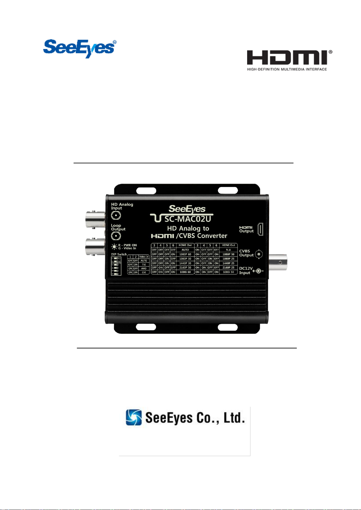
SC-MAC02U is a converter that converts HD Analog video signal into HDMI and CVBS signals.
Through loop output port, the input video can be output without converting signal. Also, you can
control the camera by connecting DVR or splitter to loop output port to send UCC signal to
camera side.
1-2. Features
•Converts HD Analog signal into HDMI, loop out and CVBS
•Camera control through loop output port
•Built-in surge protection circuit
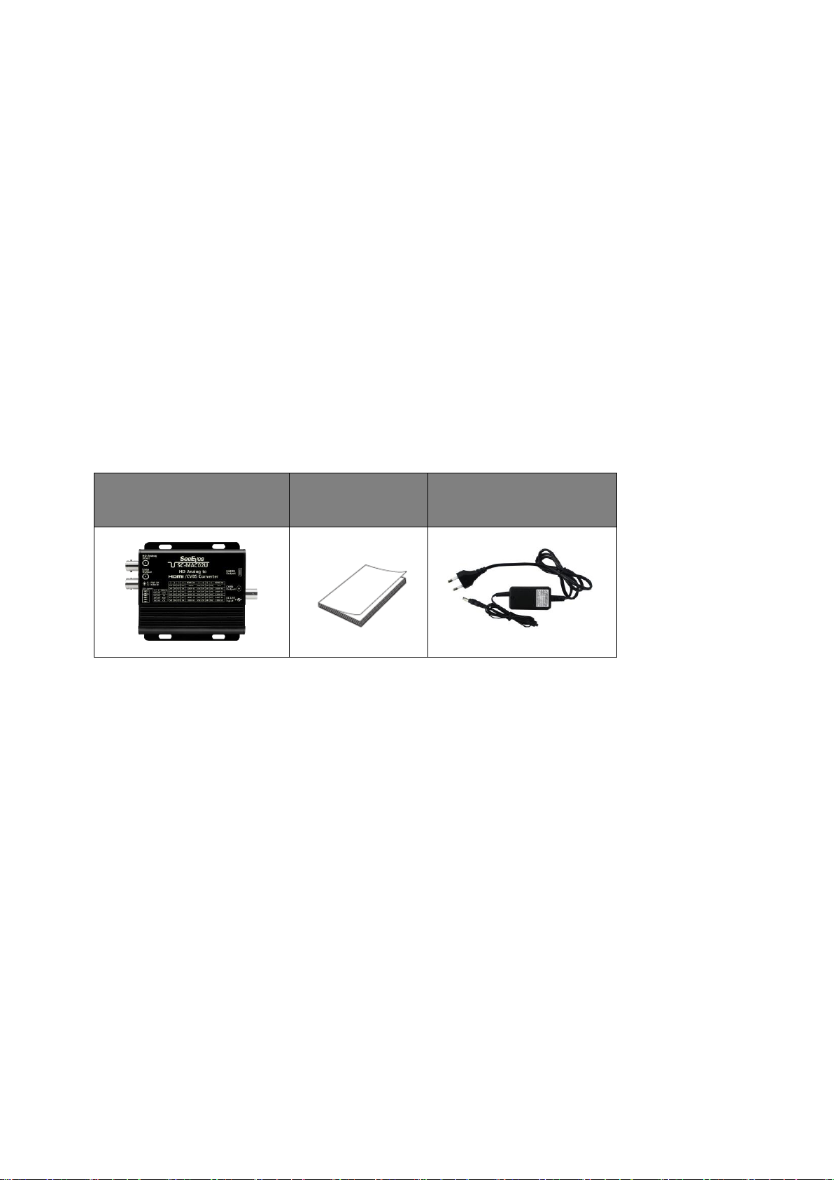
2. Components
SC-MAC02U
User’s Manual
DC 12V Adapter
(Optional)

Release Version 1.0
4
3. Product Parts & Functions
①HD Analog Input : HD Analog camera connection port.
②Loop Output : Video output port and UTC communication port.
③STATE LED : LED to display video signal input status and power input information.
LED Color
State
Description
Red
ON
Power input
OFF
No power input
Green
ON
Signal input
④Program update port (for manufacturer only) : Port to update the product.
⑤Switch Setting : Switch to select HD Analog input video and HDMl output resolution.
⑥HDMI Output : HDMI video output port.
⑦CVBS Output : Port to convert HDMI output video to CVBS video.
⑧DC 12V Input : DC 12V power input port.
②
④
⑤
⑥
⑦
⑧
①
③

Release Version 1.0
5
4. Switch Setting
4-1. Video Input Type Setting
Dip switch #1, #2 : Set the type of input video signal.
1) Auto Mode : Automatically set the type of input video.
Caution #1) Auto mode takes a little longer to display videos than Manual mode,
since Auto mode searches video signal by type.
Caution #2) In Auto mode, the video may not be displayed properly.
In this case, change the mode into Manual.
2) Manual Mode (TVI, CVI, AHD Mode) : Manually set the type of input video.
Caution) If the input video type is different with the video type selected with dip switch,
the video will not displayed properly. In this case, change the mode same as
input video type, or change the mode into Auto.
3) In case of CVBS(NTSC, PAL) input, set to Auto mode.
4-2. Video Output Resolution Setting
With the dip switch #3~6 on the side of this product, It is possible to adjust HDMI output
resolution to the resolution that you would like to display regardless of the input resolution.
CVBS output is automatically displayed as NTSC or PAL according to the output resolution selected
with the dip switch.
1) Select HDMI output resolution with dip switch #4~6.
2) Switch #3 adjusts the output resolution selected with switch #4~6 as NTSC or PAL.
Example) #3 : OFF, #4 : OFF, #5 : OFF, #6 : ON => 1080P 60
#3 : ON, #4 : OFF, #5 : OFF, #6 : ON => 1080P 50
3) You can select between two types of Auto modes.
a) Auto Mode with scaler
Set dip switch #3~6 as OFF.
Auto Mode with scaler automatically changes the HDMI output resolution according to the
input resolution.

Release Version 1.0
6
Example) If Auto Mode (scaler) is selected, the output resolution is changed as follows:
- If input resolution is CVBS, HD or FHD, the output resolution is FHD.
- If input resolution is 3MP, 4MP or 5MP, the output resolution is 4MP.
- If input resolution is 4K, the output resolution is 4K.
b) Auto Mode without scaler
Set dip switch #3 as ON, and #4~6 as OFF.
Auto Mode without scaler outputs as a higher resolution than the input resolution.
Example) Input resolution : 2048x1536(3MP18)
Output resolution : 8MP 25(3840x2160)
The different between input and output image may occur as the scaler is not used.
The different part is output as a black screen.
8MP 25 resolution is used because the vertical line of 3MP 18 (1536) is higher than
4MP 25 (1440), even though 4MP 25 (2560x1440) is also a higher resolution than
3MP 18.
<Example of Auto Mode with Scaler>
<Example of Auto Mode without Scaler >

Release Version 1.0
7
4-3. Video Information Display
When a video is input, the information of input video and HDMI output are displayed on the upper
left of the HDMI screen.
The first line indicates the type and resolution of the input video, and the second line indicates the
HDMI output resolution.
<Example of Display>
TVI : 2048x1536P 18Hz
HDMI:2560x1440P 30Hz
Video information is displayed for about 30 seconds.
This information is displayed on the screen after recognizing the video when the input video is
turned off/on or the output resolution is changed.
Caution) In other modes except Auto Mode, the video information is displayed in the video
mode set by switch #1 and #2 regardless of input video.
Example) Even if you input TVI video, the video information is displayed in AHD when the dip
switch setting is set as AHD.
Release Version 1.0
8
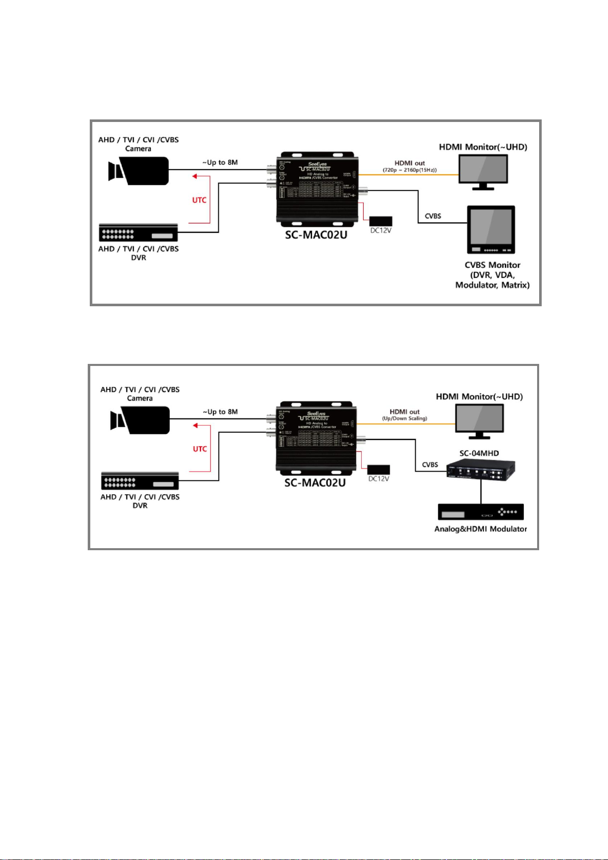
5. Connection Diagrams
5-1. Basic Connection
5-2. Connection with Quad Splitter (SC-04MHD)
※Cable transmission distance may vary depending on specifications of camera, DVR, etc.
※As AHD, TVI, CVI cameras are not standardized in signal format, the video may not be output
properly or UTC control may not work properly depending on the manufacturer.
Release Version 1.0
9
6. Transmission Distance
6-1. Video Transmission Distance (Example)
ㆍRG-59 Coax. Cable
CAM Out - DVR In
CAM Out - HD Analog In
Loop Out - DVR In
SD/CVBS Out
300m
100m
200m
100m
150m
150m
100m
200m
100m
100m
300m
1m
100m
ㆍRG-6 Coax. Cable
CAM Out -DVR In
CAM Out - HD Analog In
Loop Out - DVR In
SD/CVBS Out
500m
300m
200m
200m
350m
150m
200m
400m
100m
200m
500m
1m
200m
※Cable transmission distance may vary depending on the specifications of the camera, DVR, etc.
Above transmission distance is based on 2MP camera. In case of cameras over 4MP resolution, the
transmission distance may be decreased compared to 2MP camera.
※Even the cable length is same, the video quality and UTC transmission distance may vary
depending on the resolution of the input video.
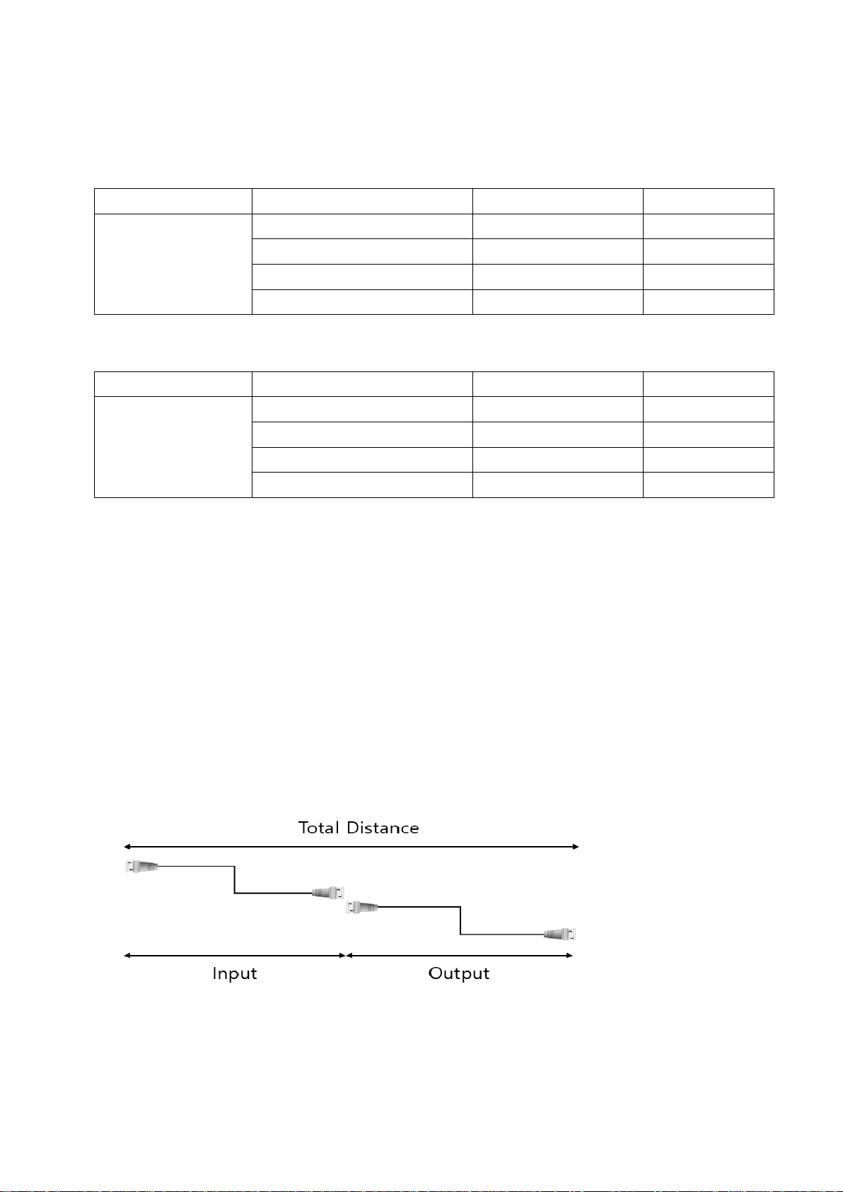
※Total distance
= (Distance from camera to HD Analog input port) + (Distance from Loop output port to DVR)
It is recommended to use HD Analog input distance and Loop output distance within total
transmission distance.
※CVBS signal does not support UTC.
※Example for Transmission Distance

Release Version 1.0
10
7. Specifications
MODEL
SC-MAC02U
HD Analog Input
- SD/CVBS : NTSC, PAL
- AHD : 720P25/30Hz, 1080P25/30Hz, 4MP15/25/30Hz,
5MP12/20Hz, 8MP12/15Hz
- TVI : 720P25/30Hz, 1080P25/30Hz, 3MP18Hz,
4MP15/25/30Hz, 5MP12/20Hz, 8MP12/15Hz
- CVI : 720P25/30Hz, 1080P25/30Hz, 4MP25/30Hz,
8MP12/15Hz
Loop Output Resolution
Same as input
HDMI Output Resolution
- 1080P25Hz, 1080P30Hz, 1080P50Hz, 1080P60Hz, 1080i50Hz,
1080i60Hz
- 1440P25Hz, 1440P30Hz
- 2160P25Hz, 2160P30Hz
SD/CVBS Output Resolution
NTSC, PAL
In/Output
Transmission
Distance
HD-Analog
In/Out
Max. 400m over RG-59 (200m/20Ω, in case of 2MP camera)
Max. 600m over RG-6 (300m/12Ω, in case of 2MP camera)
HDMI Out
HDMI Cable 3m
SD/CVBS Out
1Vp-p (75ΩTermination 시, 3C-2V Max. 100m)
Power Input / Power Consumption
DC 12V / 180mA (Max.)
Connection
Port
HD Analog Input
BNC-F 75Ω
Loop Output
BNC-F 75Ω
HDMI Output
A Type
SD/CVBS Output
BNC-F 75Ω
Switch
HD Analog Input
#1,2 (Select HD Analog input)
HDMI Output
#3,4,5,6 (Select HDMI output resolution)
LED
RED
Power ON
GREEN
Signal input ON
Temperature / Humidity
-10℃~ +50℃/ 0 ~ 80%
Case Body / Weight
Aluminum / 210g
Dimensions
93(W) x 34.7(D) x 92.5(H) mm
* 1920 x 1080i 60 HDMI resolution indicates 59.94i resolution.
60i resolution is an optional specification. Please consult with manufacturer to order it.

Release Version 1.0
11
8. Trouble Shooting Method
Symptom
Checking Method
Power is
not supplied.
•Check the adapter input state.
•Check if the exclusive adapter (DC12V, over 500m) is used.
•Check if the RED LED on the product is ON.
HDMI video is
not displayed.
•Check if the GREEN LED on the product is ON.
•Check if the input resolution is supported by the product.
•Check the HDMI cable connection state.
•Check if the resolution is supported by your monitor.
•Check the length and performance of HDMI cable.
SD/CVBS is
not displayed.
•Check if the GREEN LED on the product is ON.
•Check if the input resolution is supported by the product.
•Check the BNC connection state.
•Check if the resolution is supported by your monitor.
•Check the length and performance of BNC cable.
Video is
not clear.
•Check if the cable is properly connected.
•Check the cable connection state (length, type).
•Check if the camera is compatible with DVR.
•Check if the switch setting is properly done.
Camera control
does not work.
•Check if the camera is compatible with DVR.

Release Version 1.0
12
9. Warranty Certificate
Product No.
Model No.
Date of Purchase
Place of Purchase
Purchaser
Name
Address & Contact No.
Distributor
Name
Address & Contact No.
Warranty Period
Two(2) years from the date of purchase
Any failure that occurs in the normal use for only two years after purchase will be
repaired free of charge.
Contact the phone number listed on the user’s manual for repair.
When reporting the failure, please inform the model name and condition of the
product accurately. It is convenient to know the name and department of the person
in charge.
Please check this user’s manual again before reporting the failure.
Product shapes and circuits are subject to change without notice to improve
performance.
Faults following will be treated as a charge:
•Failure by user’s handling without care
•Not connecting the rated power
•Disassembled or repaired arbitrarily by user
•When replacing consumables
•Failure caused by natural disaster(lightning, fire, flood, tsunami, etc.)

Release Version 1.0
13
[MEMO]

Release Version 1.0
14
[MEMO]

Table of contents
Other SeeEyes Media Converter manuals

SeeEyes
SeeEyes SC-HDR01S User manual

SeeEyes
SeeEyes SC-SDHD01 User manual

SeeEyes
SeeEyes SC-16MHD User manual

SeeEyes
SeeEyes SC-16HDS User manual

SeeEyes
SeeEyes SC-HMC16E User manual

SeeEyes
SeeEyes SC-MHC01 User manual

SeeEyes
SeeEyes SC-MA8VDA User manual

SeeEyes
SeeEyes SC-MAC02 User manual

SeeEyes
SeeEyes SC-40DQH User manual

SeeEyes
SeeEyes SC-MA1VDA User manual


Popular Media Converter manuals by other brands

Blankom
Blankom HDE-264 user manual

Allied Telesis
Allied Telesis AT-GS2002 Series installation guide

Motrona
Motrona ES001 operating manual

Danfoss
Danfoss iC7 Series installation guide

Musical Fidelity
Musical Fidelity V-LINK 192 instructions

Miranda
Miranda DENSITE IRD-3811 Guide to installation and operation


