SeeEyes SC-MICP1001 User manual

Release Version 1.1
QHD Analog (AHD/TVI) VIDEO/POWER/UTC(4M/5M)
SC-MICP1001
User Manual
SC-MITP1001
SC-MIRP1001

Release Version 1.1
1
Precaution and Safety Guidelines
The content of this guideline is to protect the safety of users and prevent property damage.
Be sure to read this user’s manual thoroughly and use the device correctly.
Warning (If you do not keep any of the below guidelines, you may get seriously
injured or cause somebody’s death.)
■Be sure to install the product after unplugging power cord. Also, do not use several power plugs
at the same time.
- It may cause abnormal heat, fire and electric shock.
■Do not leave the device at any place that water falls or splashes. Also, do not put anything full of
water such as a flower vase on the device.
- It may cause malfunction or fire if liquid goes into the device.
■Do not bend the power cord by excessive force. Make sure the power cord is not crushed by
heavy things.
- It may cause fire.
■Do not open the lid arbitrarily as this device has high voltage part inside. Never disassemble,
repair or modify it.
- By abnormal working, it may cause fire, electric shock and personal injury.
■Do not install this product in places with high humidity, dust, or soot.
- It may cause electric shock and fire.
■Do not tug at the power cord section or unplug the power plug with wet hands. If the power cord
is loose, do not plug in.
- There may be a risk of fire and electric shock.
■Always keep the location of the appliance clean during or after installation to prevent dust.
Especially when cleaning the device, wipe it with dry towel and do not use water, thinner or organic
solvent.
- It may damage the case of this device, and cause malfunction or electric shock.
■Keep the device in a cool place where doesn’t let direct sunlight. Keep it at a proper temperature
and avoid heating appliances like candle or heater. Also, keep the equipment or tools away from
places where people come and go.
- It may cause fire.
■Pay attention to possible hazards in the workplace, such as wet floor, ungrounded power
extension cables, old power cords and a lack of safety earth. Consult your place of purchase or
professional if problems arise.
- It may cause fire and electric shock.
■Keep the back of the product more than 15cm and the sides more than 5cm from the wall. If you
install the product too close to the wall, it can cause the cable to be bend, compressed too hard or
break, as various external input/output ports such as power cords protrude from the back of the
product.
- It may cause fire, electric shock and personal injury.
■Concerning the input voltage for operating this device, a voltage range must be within 10% of
rated voltage, and the power outlet must be grounded. Also, do not use a heat source such as a hair
dryer, iron and refrigerator to the same power unit.
- It may cause abnormal heat, fire and electric shock.

Release Version 1.1
2
Caution (If you do not keep any of the below guidelines, you may get injured or
suffer property loss.)
■Proper ambient temperature and humidity are recommended.
- Avoid extremely high temperatures(over 50°C) or low(below -10°C), and humid conditions.
■SC-MIRP1001 PoC terminal (BNC) has superimposed DC power, so SC-MITP1001 (dedicated
transmitter) must be connected. Otherwise, connecting other devices may cause a malfunction.
■Do not place heavy items on the product or let foreign substances enter inside the device.
- It may cause failure.
■Install in well ventilated place, and avoid direct sunlight or heat appliance.
■Install at a flat and stable place. Do not use an upright or slanted position.
- It may not operate properly or might be dangerous due to the fall of the device.
■Strong shock or vibration may cause device failure. Be careful when using the device.
- Install in a place without severe vibration.
■Be sure to check the specifications and usage method of the device before installation.
■Leave enough space to allow heat dissipation between devices.
■Refer the device to the service center and get regular checkup to maintain the performance of the
system.
- We are not responsible for any damages caused by user’s carelessness.
■Place the power plug in a location that is easy to operate.
- If a failure of the product occurred, the power plug must be unplugged to power down completely. The power button on
the main body of the product does not completely cut off the power.
■Disconnect the power plug with care during thunder and lightning.
■Before applying power, check that the dedicated camera and dedicated transmitter of the
PoC terminal are connected once again.
■Refer to the user’s manual for problems or questions besides the above. Contact our service
center if you need assistance from a professional technician.
■To extend or terminate the coaxial cables, you should connect them in the following way.
- BNC-M(Male) - BNC-JJ - BNC-M(Male): BNC Connector Connection Example
■Make the joint part of the cables insulated completely not to expose the metal parts.
Release Version 1.1
3
1. Introduction
1-1. Summary
SC-MICP1001 is a kit capable of long-distance transmission of AHD and TVI signals and consists of
SC-MITP1001 (transmitter) and SC-MIRP1001 (receiver). It can transmit power, video, and UTC via 1
coaxial cable up to 350m(RG-59).
It is strong against ambient noise, and new or existing coaxial cables can be used without signal
loss, and it is convenient for installation and maintenance as there is no need for a separate power
line.
1-2. Product Features
•Power + video + UTC signals on one coaxial cable for transmission
•Supports AHD, TVI signals up to 5M/20p (2MP, 4MP, 5MP)
•Transmission up to 350m with RG-59 coaxial cable
•Provides power to operate the camera (up to 10W)
•Increase productivity during construction as one coaxial cable is essential.
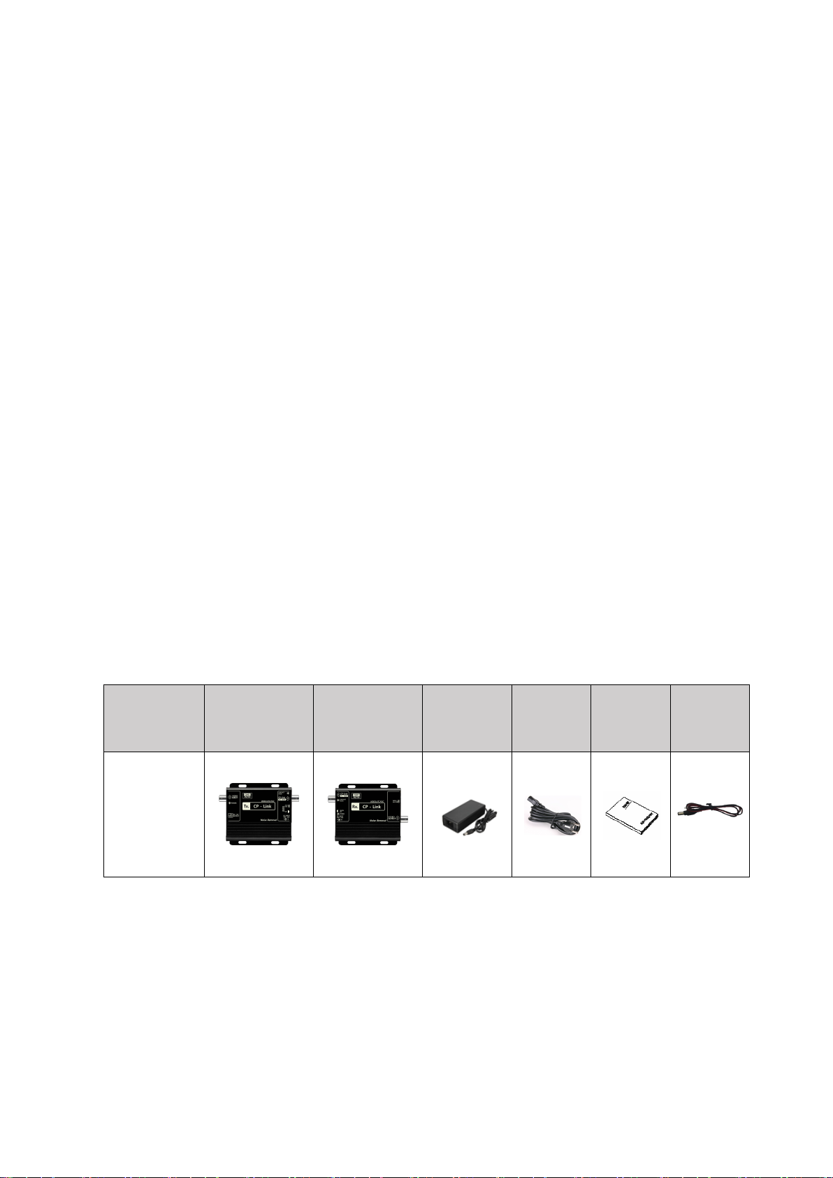
2. Components
Model
Transmitter
Receiver
DC 56V or
48V
Adapter
Power
cord
User
manual
Lead cable
SC-MICP1001
Release Version 1.1
4
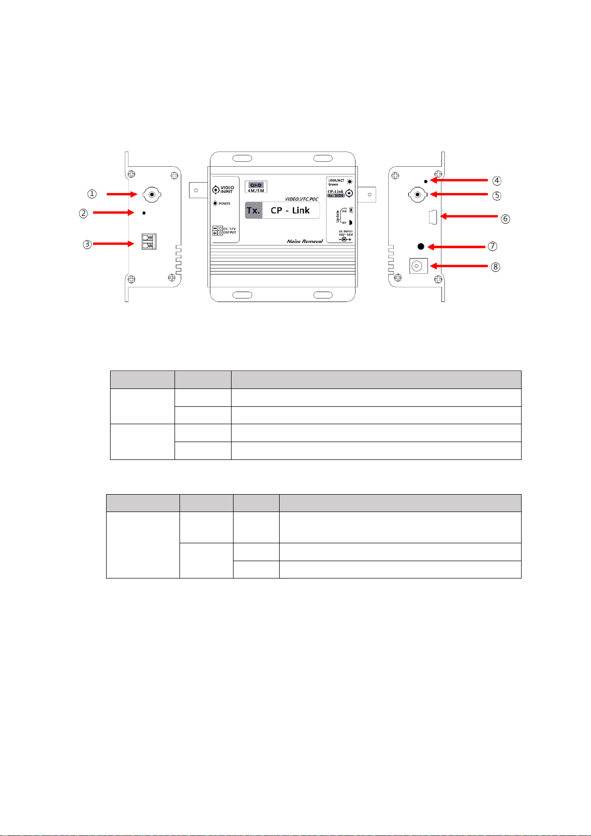
3. Names and functions of each part
3-1. SC-MITP1001(Transmitter)
⚫Supports UTC function to control the camera's menu.
⚫Up to 10W cameras can be connected depending on coaxial cable conditions.
①VIDEO INPUT: HD-Analog video input terminal
②POWER LED: Power status LED indicator
LED
Status
Description
Red
OFF
Power OFF
ON
Power ON
Red +
Green
OFF
No connection between transmitter and receiver
ON
Successful connection between transmitter and receiver
③DC12V OUTPUT:DC12V/0.84A (10W) power output terminal (applied with lead wire)
④LINK, ACT status LED indicator
Function
LED
Status
Description
LINK/ACT
Green
OFF
No connection between transmitter and receiver
Green
ON
LINK ON
Blinking
ACT ON
⑤CP-LINK OUTPUT(Rx SIDE): Terminal for connecting receiver via coaxial cable
⑥Update mini USB: Firmware Update terminal
⑦Update KEY:Initial operation key for firmware update
⑧DC INPUT: DC power input terminal (DC48V - DC56V)

Release Version 1.1
5
3-2. SC-MIRP1001(Receiver)
⚫It supplies power to the transmitter and receives video signal from the transmitter.
⚫IT transmits UTC data from DVR to transmitter.
①CP-LINK INPUT(Tx SIDE):Terminal for connecting transmitter via coaxial cable
②LINK, ACT status LED indicator
Function
LED
Status
Description
LINK/ACT
Green
OFF
No connection between transmitter and receiver
Green
ON
LINK ON
Blinking
ACT ON
③Update KEY:Initial operation key for firmware update
④POWER LED: Power status LED indicator
LED
Status
Description
Red
OFF
Power OFF
ON
Power ON
Red +
Green
OFF
No connection between transmitter and receiver
ON
Successful connection between transmitter and receiver
⑤DC INPUT:DC power input terminal (DC48V - DC56V)
⑥Update mini USB: Firmware Update terminal for the manufacturer
⑦VIDEO OUT:HD-Analog video output terminal (connected to DVR, etc.)
Release Version 1.1
6
4. Installation guide
4-1. Check list before installation
Supply SC-MICP1001 with power after confirming once again that the transmitter and
receiver are properly installed.
•Installation Order:
Connect the DC12V output of the transmitter to the power input of the camera → Connect the
transmitter and the receiver with a coaxial cable → Connect the video signal output of the
receiver to the DVR or MONITOR → Double-check that the connection is properly done →
Connect the DC adapter power to the receiver
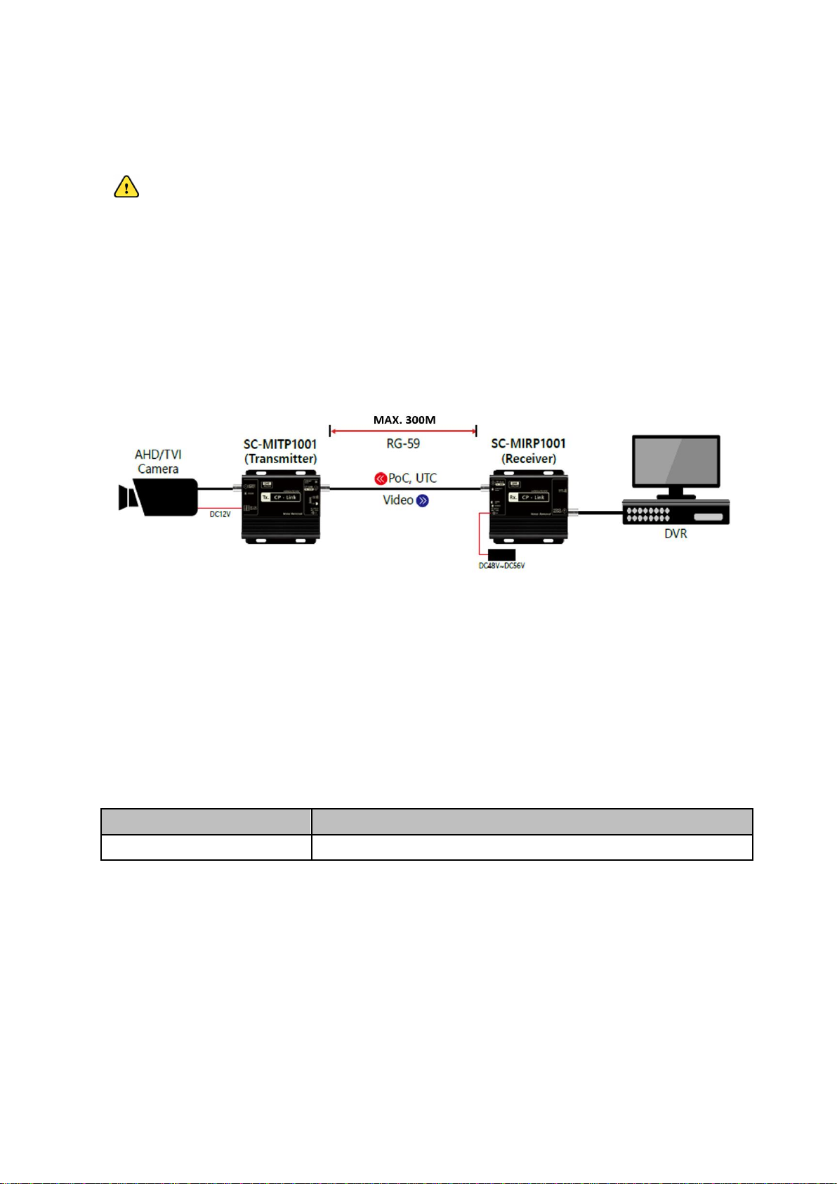
4-2. Application diagram
4-3. Power supply compatibility and installation precautions
●Be sure to use a dedicated transmitter/receiver/power adapter to prevent malfunctions in case
of wrong connection to DVR or DC12V camera.
●It may take up to 45 seconds to output the video after turning on the power.
- There may be differences depending on the camera and DVR.
※PoC power transmission distance
•The power transmission distance may vary depending on the camera's power consumption.
•The maximum PoC is 10W, but be sure to check the availability before installing.
•L/R = Loop Resistance of the coaxial cable, and it is recommended to use a maximum of 22Ω or
less.
•If the camera is used in excess of power consumption and loop resistance, it is recognized as
overcurrent and the power supply can be cut off.
•The transmission distance may differ depending on the specifications of the camera, DVR, etc.
Camera power consumption
Via RG-59 (L/R: 10Ω), Extended setting
10W
300m

Release Version 1.1
7
※Cautions when installing cables
•When connecting coaxial cables and working with connectors, it is recommended to use BNCs with
low connection resistance.
•When installing, pay attention to cable deformation due to pressure (Squashed cable).
•When installing, do not pull with excessive force.
•The video and power transmission distance and quality may vary depending on the type of cable,
the working condition of the connector, and the type of connection adapter.
■Transmission distance
Power input
DC56V
DC48V
Coaxial type
Manufacturer
Loop
Resistance(Ω)
/200m
Camera Power
consumption
Camera Power consumption
10W
10W
8W
PoC distance(m)
PoC distance(m)
PoC distance(m)
5C-HFBT
U-JIN
8.32
500
500
500
KUMKANG
10
500
500
500
L-5CFB
CANARE
6.2
500
500
500
L-5C-2V
CANARE
8.8
500
500
500
L-3C-2V
CANARE
21
350
260
500
S-5C-FB
TACHII
7.4
500
500
500
S-5C-FV
TACHII
7.5
500
500
500
1694A 18AWG
Belden
6.1
500
500
500
RG59/U(1505A)
BELDEN
9.1
300
300
300
RG58/U
KUMKANG
11.4
300
300
300
■Supported resolutions
Category
Resolution
TVI
AHD
2MP
1080P25
O
O
1080P30
O
O
4MP
1440P25
O
O
1440P30
O
O
5MP
1944P20
O
O
※UTC operation specifications may differ depending on camera and DVR specifications.
※For AHD and TVI cameras, since the signal format is not standardized, the video may not
be output normally depending on the manufacturer, and the UTC control may not work
properly.

Release Version 1.1
8
5. Troubleshooting
Symptoms
Check list
No power
•Check that the DC adapter is properly connected.
•Check if the dedicated DC adapter (DC 48V to DC 56V) is used.
•After connecting the DC adapter, check if the RED LED of the
transmitter/receiver is on when power is applied.
•Check the connection of the BNC connector.
No video
•Check if the Green LED (Normal ACT status) of the
transmitter/receiver is blinking.
•Check that the coaxial cable is connected properly.
•Check the connection of the BNC connector.
•Check that DC12V power is input to the camera.
•Check whether the camera and DVR are compatible with each
other.
Unclear video or noise
occurs
•Make sure the cable transmission distance is within the
recommended distance.
•In the case of a low-cost cable, signal attenuation is very low even
within the recommended distance.
It may be large, so check the attenuation rate of the cable.
•Check whether the camera and DVR are compatible.
•Check if there are repeaters or high-voltage lines in the vicinity.
No UTC
•Check whether CAMERA and DVR are compatible with each other.
•Check the communication mode setting of DVR.
•Check if the transmission distance is exceeded.

Release Version 1.1
9
6. Specifications
MODEL
SC-MITP1001
SC-MIRP1001
Signal
Input signal
AHD, TVI
CP-Link(Digital Signal)
Output signal
CP-Link(Digital Signal)
AHD, TVI
Resolution
2MP, 4MP, 5MP
Transmission distance(RG-59)
Up to 300m
Resolution supported with UTC
AHD/TVI : 2MP, 4MP, 5MP
External Interface(For only update)
MIIN USB 1Port
Power input
PoC or DC 48V - 56V
DC 48V - 56V
Power output
DC 12V, 0.84A(10W)
N/A
Power consumption
DC56V/55mA,
DC48V/60mA
DC56V/50mA
DC48V/55mA
Temperature / Humidity
-10°C ~ +50°C / 0 ~ 80%
Color / Case
Black / Aluminum
Dimensions(mm)
93(W) x 35(D) x 93(H)
93(W) x 35(D) x 93(H)
Weight
200g
200g
* DC48V adapter is optional
* Depending on the camera and DVR manufacturer, UTC operation may not be working due to
compatibility between devices.
* Video delay may occur depending on the camera resolution.

Release Version 1.1
10
7. Warranty Certificate
This product has passed thorough quality control and test, and if this gets broken during
normal use, we provide the two-year warranty service.
Model No.
Serial No.
Distributor
Date you purchased
Place you purchased
Warranty Period
Two (2) year from the date of purchase
Purchaser
Name
Address
•Please check this warranty indication first.
•Please contact your distributor after checking out any defect in the products.
•The standard for repairing, replacement or reimbursement follows Customer.
•Warranty content any defect under normal use within the warranty service period we
give you free repair service according to the warranty certificate.
•We charge you with the fee of parts and service despite of free warranty service period.
Any breakage made without care such as:
- Breakage or trouble made by natural disaster.
- Breakage or trouble made by breaking the product guide or manual.
- Breakage or trouble made by wrong power voltage or frequency.
- When you want to reassemble for full system or replace parts within warranty
service period.
- When unauthorized person modified or made damage on the product trying to
repair it.
- Lightning strike.
•Please note that we don’t support the breakage after warranty service period is expired.
If the customer wants to get it repaired, we charge them with the fee.
•The specification is subject to change without prior notice for quality improvement.

Release Version 1.1
11
S
Se
ee
eE
Ey
ye
es
s
C
Co
o.
.,
,L
Lt
td
d
#503~509 Sunil Technopia, 555 Dunchon-daero, Jungwon-gu, Seongnam City,
Gyeonggi Province, Korea (Zip Code: 13215)
T
TE
EL
L:
:
+
+8
82
2-
-(
(0
0)
)3
31
1-
-7
73
30
0-
-5
58
83
33
3
F
FA
AX
X:
:
+
+8
82
2-
-(
(0
0)
)3
31
1-
-7
77
77
7-
-3
35
51
12
2
E
E-
-M
MA
AI
IL
L
:
:
o
ov
ve
er
rs
se
ea
as
s@
@s
ss
sc
cc
ct
tv
v.
.c
co
om
m
h
ht
tt
tp
p:
:/
//
/w
ww
ww
w.
.s
ss
sc
cc
ct
tv
v.
.c
co
om
m/
/e
en
ng
g
This manual suits for next models
2
Table of contents
Other SeeEyes Receiver manuals


