SeeEyes SC-UT0124H/H6 User manual

ACTIVE UTP RECEIVER WITH AUTO VIDEO LEVEL CONTROL
SC-UT0124H/H6
SC-UR0124H
SC-UR1618H
User's Manual
SC-UR0124H
SC-UT0124H/H6
SC-UR1618H

1
Precaution and Safety Guidelines
Please read this user’s manual thoroughly prior to use the unit for
its easy and convenient use.
Do not install the product in the following places: extremely low or high
temperature conditions; places exposed to rain, snow, or high
humidity; places containing or exposed to oil and gas; places exposed
to vibration and shock; places under direct sunlight or exposed to
outdoor weather conditions; places exposed to radio waves (RF) or near
to power lines. It may cause low performance or malfunction of the unit.
Do not disassemble the unit and do not insert any foreign objects inside
the unit. It may cause malfunction or damage to the unit.
To reduce the risk of fire or electric shock, please be careful on electric
shock when using the unit.
Please using only power supply units or equipment corresponding to the
unit in order to avoid any fire risk or or malfunction of the unit.
The optimum ambient temperature for the use of the Device is -10°C ~
50°C, and it needs to be careful when the Device is used for both inside
and outside the building.
Should be careful not to have the lines changed when connecting them.
When you connect the operating power line to the Camera, you should
confirm if the Camera uses AC or DC power, and for the case of DC
power then you should be careful not to have the polarity changed to
the wrong one (If you connect the AC Adapter to Transmitter, and
connect the DC Adapter to the Receiver, then it would cause a
breakdown).
Please turn on the switch for power supply after confirming the
insulation condition of the control cable connected from the outside.
Giving a strong vibration or impact to the Device could cause a
breakdown, therefore adequate precautions should be taken when
installing or using the Device.
Do not use the device when any smoke or smell is produced from the
unit. It may be subject to fire or electric shock. If any smoke or smell is
produced, please turn off the unit and remove the power cable
immediately, and contact your distributor to check the device properly.
If the power is not ON, please check whether the power cable is
connected correctly or not.
If the device is not working properly, please contact your distributor.
2
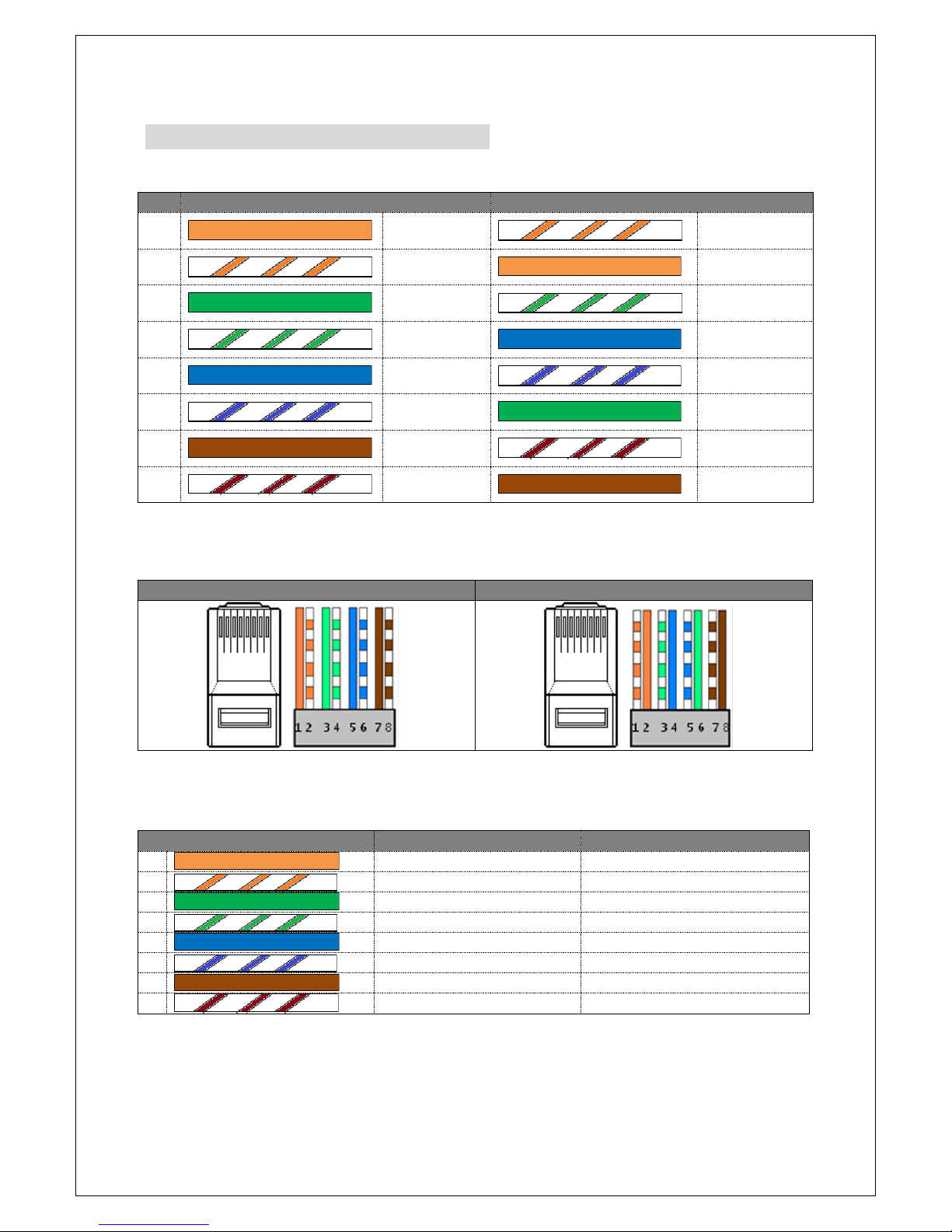
How to connect the UTP cable
4Pairs of UTP cable Wiring System
NO
SeeEyes
TIA / EIA 568B
1
Orange
White &
Orange
2
White &
Orange
Orange
3
Green
White &
Green
4
White &
Green
Blue
5
Blue
White &
Blue
6
White &
Blue
Green
7
Brown
White &
Brown
8
White &
Brown
Brown
Please note that the SeeEyes UTP cable wiring method is different from TIA/EIA 568B
method.
RJ-45 JACK Wiring
SeeEyes
TIA / EIA 568B
Please note that SeeEyes RJ-45 Wiring method is different from TIA/EIA 568B.
When using the Junction Box (UTP power supply unit), connect the UTP
cable as below.
Cable #
Camera
Receiver or DVR
1
VIDEO (+)
CAMERA 1 (+)
2
VIDEO (-)
CAMERA 1 (-)
3
RS-485 (+)
CAMERA 2 (+)
4
RS-485 (-)
CAMERA 2 (-)
5
CAMERA POWER (+)
CAMERA 3 (+)
6
CAMERA POWER (+)
CAMERA 3 (-)
7
CAMERA POWER (-)
CAMERA 4 (+)
8
CAMERA POWER (-)
CAMERA 4 (-)
3
1. Introduction
1.1. Overview
The SC-UT0124H (Tx.) & SC-UT0124H6 (Tx.) together with SC-UR0124H or SC-
UR1618H are able to perform the long distance video transmission with excellent
immunity interference. Using these solutions, you can transmit video signals
from 1.8km away in color and 2.4 km away in B/W via Twisted Pair Cable (UTP,
FTP, STP). Also, you can transmit PTZ data and supply power to the camera (SC-
UT0124H6) by using the surplus insulated conductors.
※The transmission distance and the interference immunity effect may vary when
using the SC-UT0124H/SC-UT0124H6/SC-UR0124H/SC-UR1618H together with
other UTP models. It is recommended to use the SC-UT0124H together with the
SC-UR0124H or SC-UR1618H as a set for optimum performance.
1.2. Features
•Active type UTP transmitter with excellent interference immunity
•Video transmission distance up to 1.8km in color and 2.4km in B/W via
CAT.5 UTP cable
•With the passive balun(SC-TP0104C), the SC-UR0124H/SC-UR1618H can
transmit the video up to 1km.
•High performance of high quality video transmission and excellent
interference immunity
•SC-UR0124H: 2-step distance adjusting switch (Low: under 900m, High:
between 900m~ 2.4km).
•SC-UR1618H: Auto distance adjustment function
•Able to select an optimum level video by adjusting A.Level/F.Level gain
control.
•Minimize crosstalk or interference caused from the cable
•SC-UT0124H: Possible to use the camera adapter in parallel due to its low
power consumption.
•SC-UT0124H/SC-UR0124H: Possible to use 24VAC /12VDC~49VDC power.
•Surge protection feature
•LED Indicator for video connection
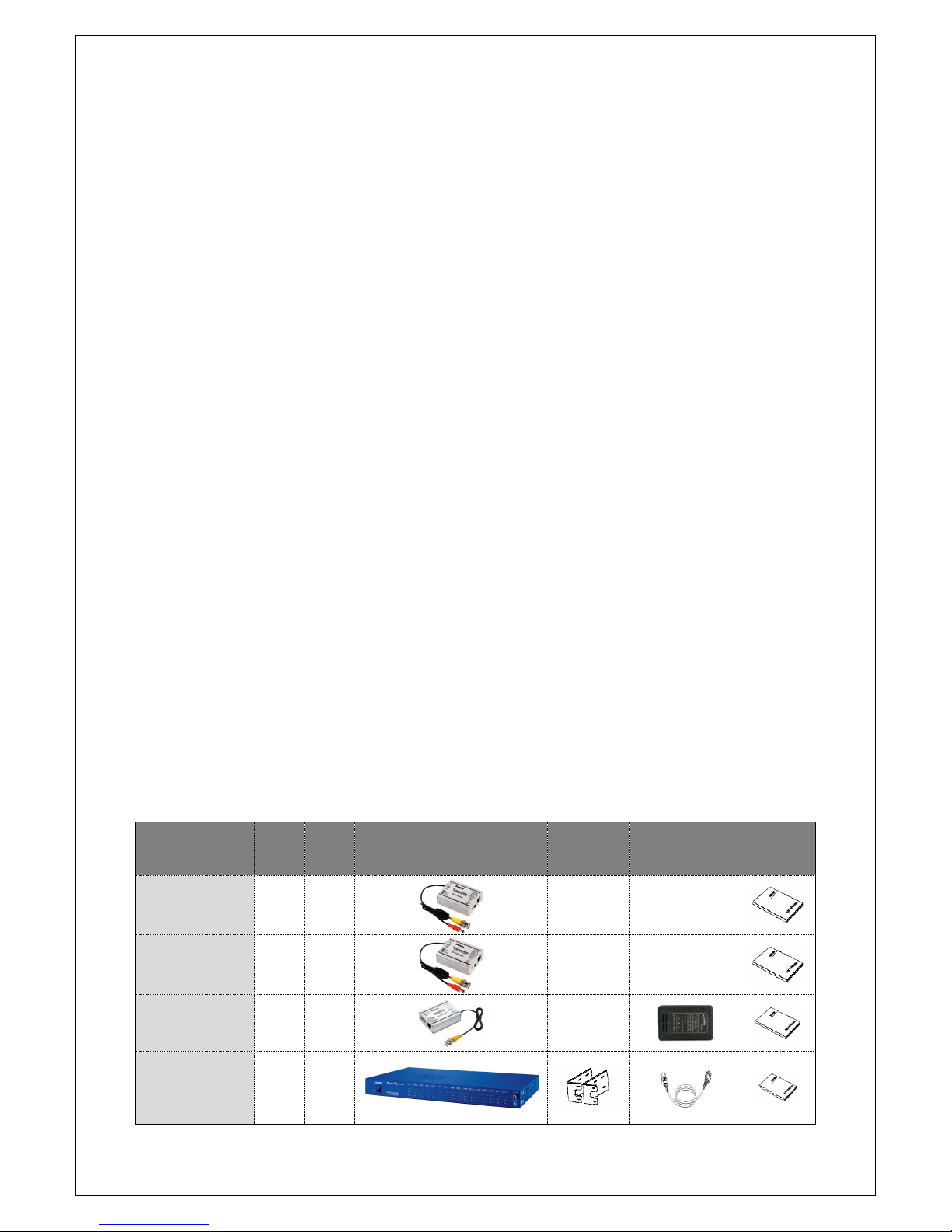
2. Components
2.1. Components per model #
Model #
Tx.
Rx.
Image
Rack
Bracket
Power
cord,
adapter
User’s
Manual
SC-UT0124H
○
SC-
UT0124H6
○
SC-UR0124H
○
SC-UR1618H
○

4
3. Product Parts and Peripheral Device Connection
3.3. Part Names and Functions
3.1.1. SC-UT0124H, SC-UT0124H6
①VIDEO IN: Connect with the video output terminal of Camera.
②CAM POWER: Driving power output terminal of Camera.
For cameras using separate power, it should not be connected.
③RS-485: RS-485 DATA connection terminal. To be careful with Polarity
④POWER IN: Used when a separate Adapter needs to be connected.
If the power is supplied by a Junction Box (Power supply unit), it should
not be connected.
⑤UTP CABLE: Connect an UTP Cable attached with RJ-45 Plug.
⑥CABLE LENGTH: Adjust the H/L according to the UTP Cable distance.
Maximum transmission distance L: 900m or less / H: 900m ~ 2.4km.
The distance may vary depending on the cable status.
⑦POWER LED: If power is supplied to the SC-UT0124H, the Power LED
is turned on in red color.
※How to supply power
- When using SC-JPDXXX series (48VDC Junction Box) to supply power to
cameras with 12VDC., use the SC-UT0124H6 as transmitter and connect the
units as below. It is possible to supply power max. 6W (12VDC, 0.5A) from
900m away.
- When supplying power to the camera by a separate power adapter, please

5
connect the equipment as below.
•Notes:
- When using separate power supply unit (power adapter) to feed the
camera and the transmitter and connecting the SC-UT0124H/H6 to the
receiver or the junction box one to one (1:1), please cut the power lines #
5,6,7,8 of the UTP cable as below.
- The power can pass via the lines #5,6,7,8 and flows backward to the
receiver or the junction box, causing malfunction of the devices.
- When the SC-UT0124H is sharing the power supply adapter with the camera
as above, please use the power adapter corresponding to the camera,
because the power will pass by through the harness cable of transmitter. For
instance, if the camera use 12VDC power, use a power adapter with 12VDC.
- The SC-UT0124H6 can convert the 12~48VDC or 24VAC input power via UTP
cable or the terminal block to 12VDC/0.5A and put out 12VDC/0.5A power to
the camera.
•SC-UT0124H VS. SC-UT0124H6
Model #
Power
Input
DC DOWN
Converter
Camera Driving Power
Function
UT0124H
24VAC
12~48VDC
X
BYPASS Power from the
PSU
Video
Transmission
UT0124H6
24VAC
12~48VDC
O
Supplying 12VDC 0.5A from
the 48VDC input power
Video+Power to
the camera
Cut # 5,6,7,8
6
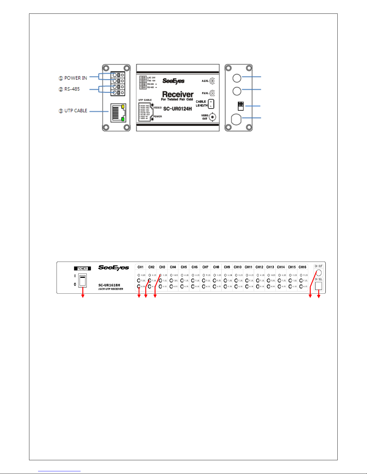
3.1.2. SC-UR0124H
①POWER IN: Adaptor connection terminal.
②RS-485: RS-485 DATA connection terminal. Be careful with polarity.
③UTP CABLE: Connect the UTP Cable attached with a RJ-45 Plug.
Yellow LED: Video, Green LED: Power
④A. LEVEL: Adjust video image level.
⑤F. LEVEL: Make a fine adjustment for video image.
⑥CABLE LENGTH: Adjust the H/L switch the depending on the UTP cable.
Maximum transmission distance L: 900m or less / H: 900m ~ 2.4km.
The distance may vary depending on the cable status.
⑦VIDEO OUT: Connect with the video image input terminal of DVR,
Monitor or Quads.
3.1.3. SC-UR1618H
3.1.3.1. Front
①POWER ON/OFF SWITCH.
②A.Level (Brightness): Adjust the video level minutely in the following
order.
A. LVL ⇒F. LVL ⇒A. LVL ⇒F. LVL
※If the video level is too high, it may cause crosstalk depending on the DVR.
In this case, please lower the video level of the each channel.
③F. Level(Color)
④VIDEO IN Indicator: It turns on the LED when the video signals are
connected.
⑤CH OUT: You can put out the video signals of the channel selected from
CH SEL (⑥) and display the video selected in a monitor or adjust the
video signals of the selected channel easily.
⑥CH SEL: Select the channel you want to put out through the CH OUT
port (⑤).
①②③④⑤⑥
⑥Cable Length
⑤F. Level
④A.Level
⑦Video Out
7
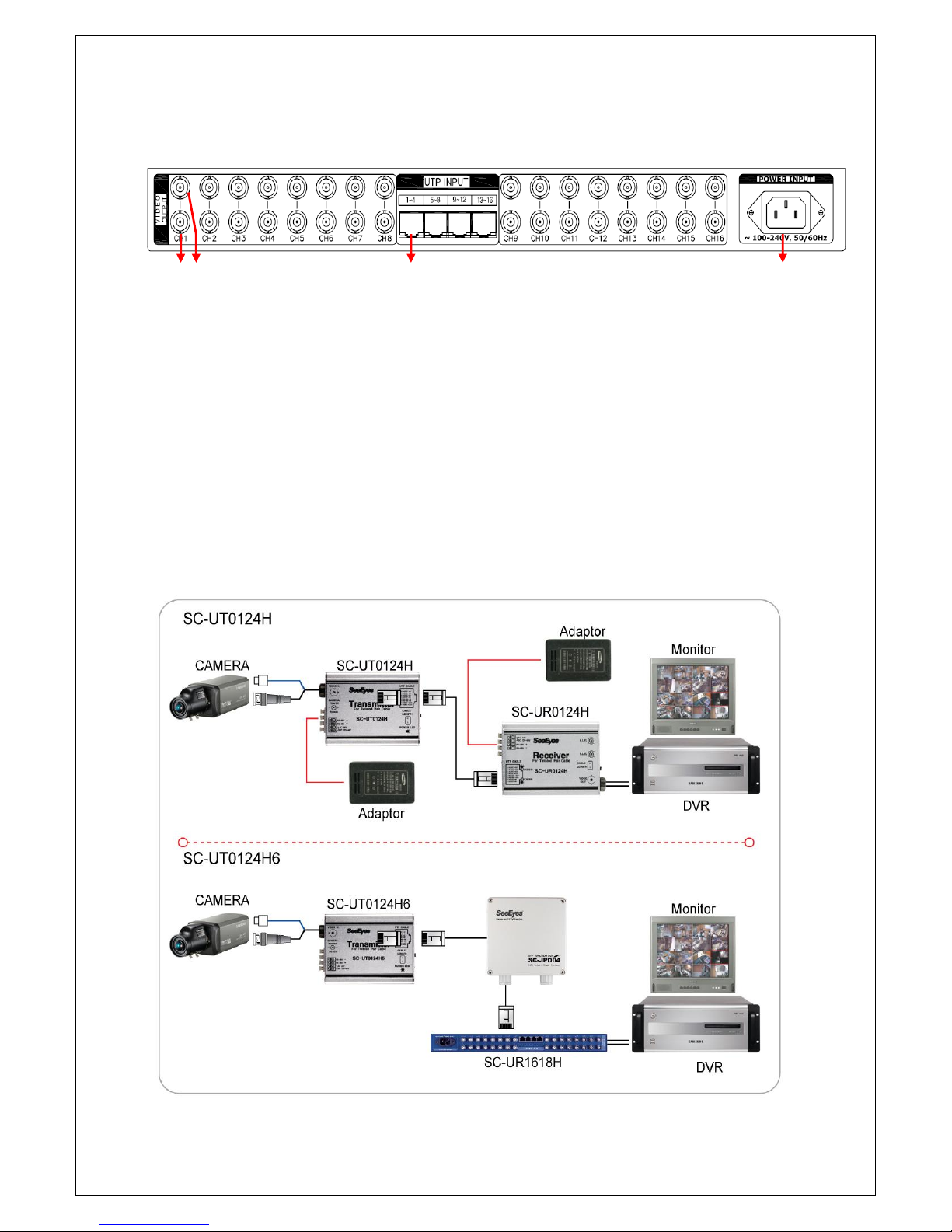
3.1.3.2. Rear side
①, ②VIDEO OUTPUT (BNC-F): Put out sixteen (16) videos received
from the UTP cable. Connect to the DVR or Monitor.
③UTP INPUT: Receive sixteen (16) video signals
- Each RJ-45 Jack port receives 4 videos.
- Please refer to the UTP cabling method.
④AC INNET: Power input - 100-240VAC, 50/60Hz
4. Application
Please refer to the below connection diagram prior to installation.
4.1. SC-UT0124H / SC-UT0124H6 / SC-UR0124H
①② ③④
8
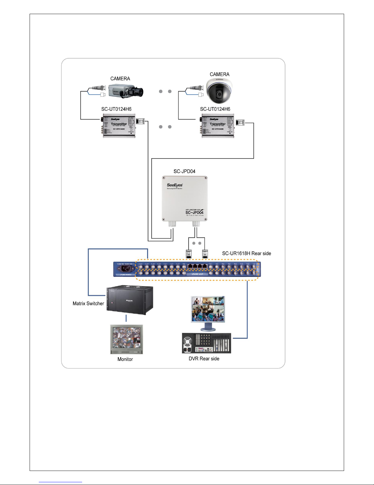
4.2. SC-UR1618H
9
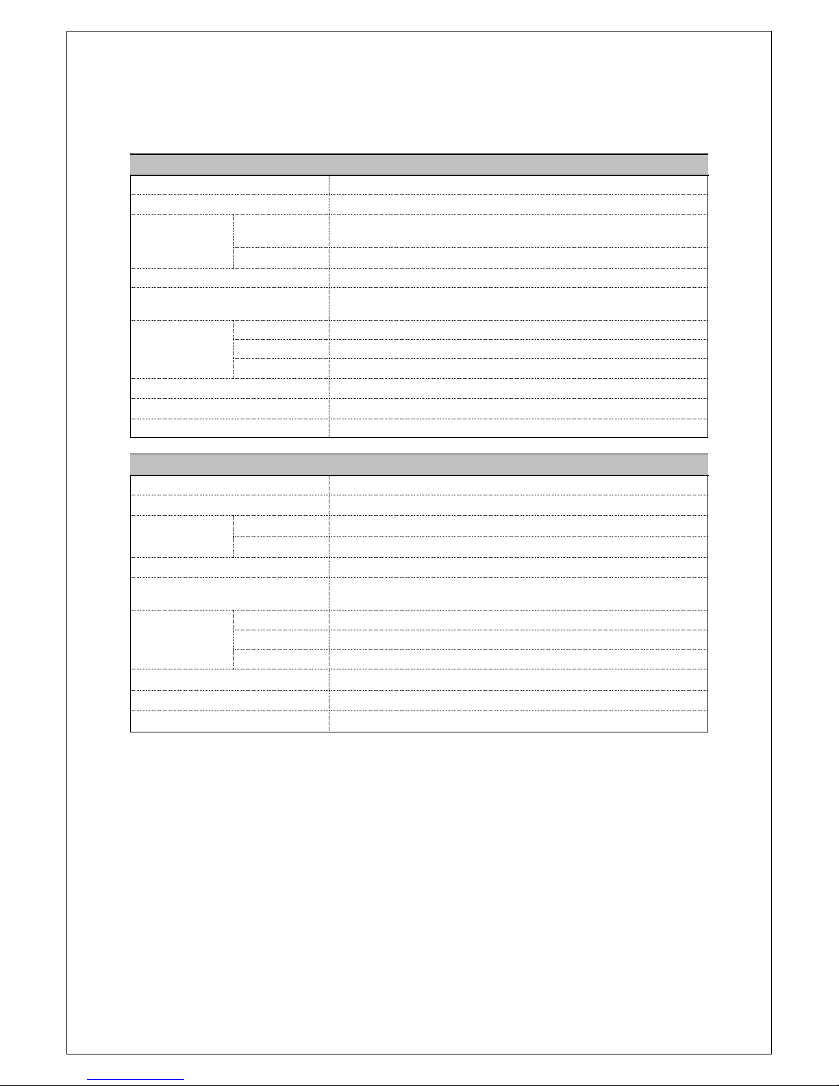
5. Specification
MODEL
SC-UT0124H(1ch Transmitter)
Video Input
CVBS 1.0Vp-p, 75Ω
Video Output
51Ω 1Vp-p ~ 8Vp-p
Power
Input
Camera adapter
(24VAC / 12VDC~48VDC)
Output
Bypass
Bandwidth
1.8 Km:6MHz
Maximum Transmission
Distance (CAT 5)
Low: under 900m, High: 900m~2.4Km
Connection
Port
Video Input
DC-M & BNC-M Harness Cable(45Cm)
Video Output
RJ-45
DATA
DATA: 4P Terminal Block(2P Data/ 2P Power)
Temperature /Humidity
-10℃~ +50℃/ 0 ~ 80%
Material / Weight
Aluminum / 120g
Dimension
78(W) ⅹ60(H) ⅹ25(D)mm
MODEL
SC-UT0124H6(1Ch Tx. with DC/DC Down Converter)
Video Input
CVBS 1.0Vp-p, 75Ω
Video Output
51Ω 1Vp-p ~ 8Vp-p
Power
Input
PSU (SC-UPD08, JPDXX) Power (48VDC)
Output
DC 12V 500mA
Bandwidth
1.8Km : 6MHz
Maximum Transmission
Distance (CAT 5)
Low: under 900m, High: 900m~2.4Km
Connection
Port
Video Input
DC-M & BNC-M Harness Cable(45Cm)
Video Output
RJ-45
DATA/ Power
DATA: 4P Terminal Block(2P Data/ 2P Power)
Temperature /Humidity
-10℃~ +50℃/ 0 ~ 80%
Material / Weight
Aluminum / 120g
Dimension
78(W) ⅹ60(H) ⅹ25(D)mm

10
MODEL
SC-UR0124H (1Ch Receiver)
Video Input
51Ω 1Vp-p ~ 8Vp-p
Video Output
CVBS 1.0Vp-p, 75Ω
Power consumption
30mA
POWER
INPUT
Adapter: 24VAC, 12~48VDC
OUTPUT
Bypass
Bandwidth
1.8Km : 6MHz
Maximum Transmission
Distance (CAT 5)
Low: under 900m, High: 900m~2.4Km
Video Level Control
VR (A. Level / F. Level), H/L selectable
Connection
Port
Video Input
RJ-45
Video Output
BNC-M Harness Cable(45Cm)
DATA/ Power
DATA: 4P Terminal Block(2P Data/ 2P Power)
Temperature /Humidity
-10℃~ +50℃/ 0 ~ 80%
Material / Weight
Aluminum / 120g
Dimension
78(W) ⅹ60(H) ⅹ25(D)mm
MODEL
SC-UR1618H (16Ch Receiver)
Video Input
51Ω 1Vp-p ~ 8Vp-p
Video Output
Output 1
CVBS 1.0Vp-p, 75Ω
Output 2
CVBS 1.0Vp-p, 75Ω
POWER
INPUT
AC 100~240V 50/60Hz
Power
consumption
10W
Bandwidth
1.8Km : 6MHz
Maximum Transmission
Distance (CAT 5)
Color: 1.8Km
Distance Adjustment
High, Low Auto adjustment
VR Adjustment (A. Level / F. Level)
Connection
Port
Video Input
RJ-45 MODULA PLUG
Video Output
BNC-F
Temperature /Humidity
-10℃~ +50℃/ 0 ~ 80%
Material / Weight
Steel/ 2.7Kg
Dimension
430(W) ⅹ44(H) ⅹ250(D)mm

11
6. Warranty Certificate
This product has passed thorough quality control and test, and if
this gets broken during normal use, we provide 12 months
warranty service.
Model No.
Serial No.
Distributor
Date you purchased
Place you purchased
Warranty Period
One (1) year from the date of purchase
Purchaser
Name
Address
•Please check this warranty indication first.
•Please contact your distributor after checking out any defect in
the products.
•The standard for repairing, replacement or reimbursement
follows Customer.
•Warranty content any defect under normal use within the
warranty service period we give you free repair service
according to the warranty certificate.
•We charge you with the fee of parts and service despite of free
warranty service period. Any breakage made without care such
as:
- Breakage or trouble made by natural disaster.
- Breakage or trouble made by breaking the product guide
or manual.
- Breakage or trouble made by wrong power voltage or
frequency.
- When you want to reassemble for full system or replace
parts within warranty service period.
- When unauthorized person modified or made damage on
the product trying to repair it.
•Please note that we don’t support the breakage after warranty
service period is expired. If the customer wants to get it
repaired, we charge them with the fee.
•The specification is subject to change without prior notice for
quality improvement.
•
•
•
•
•
•
S
Se
ee
eE
Ey
ye
es
s
C
Co
o.
.,
,L
Lt
td
d
#
#5
50
02
2~
~5
50
06
6,
,
S
Su
un
ni
il
l
T
Te
ec
ch
hn
no
op
pi
ia
a,
,
4
44
40
0,
,
S
Sa
an
ng
gd
da
ae
ew
wo
on
n-
-D
Do
on
ng
g,
,
J
Ju
un
ng
gw
wo
on
n-
-G
Gu
u,
,
S
Su
un
ng
gn
na
am
m-
-S
Si
i,
,
G
Gy
ye
eo
on
ng
gg
gi
i-
-D
Do
o,
,
K
Ko
or
re
ea
a
T
TE
EL
L
:
:
+
+8
82
2-
-(
(0
0)
)3
31
1-
-7
77
77
7-
-3
35
50
08
8
F
FA
AX
X
:
:
+
+8
82
2-
-(
(0
0)
)3
31
1-
-7
77
77
7-
-3
35
51
12
2
E
EM
MA
AI
IL
L
:
:
o
ov
ve
er
rs
se
ea
as
s@
@s
ss
sc
cc
ct
tv
v.
.c
co
om
m
h
ht
tt
tp
p:
:/
//
/w
ww
ww
w.
.s
ss
sc
cc
ct
tv
v.
.c
co
om
m/
/e
en
ng
g
This manual suits for next models
2
Table of contents
Other SeeEyes Receiver manuals


