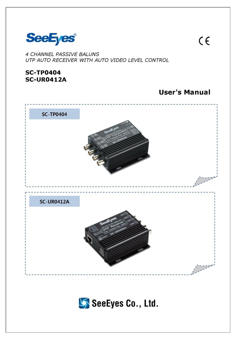
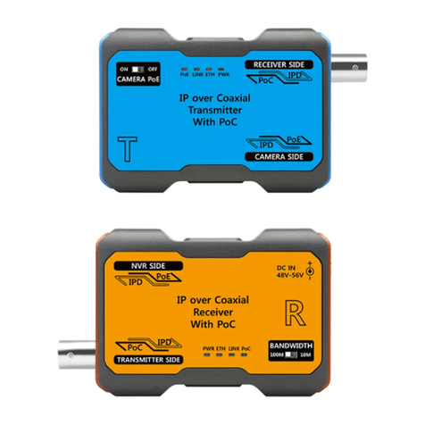
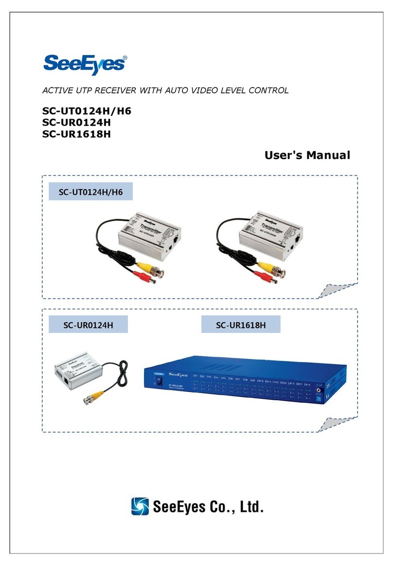
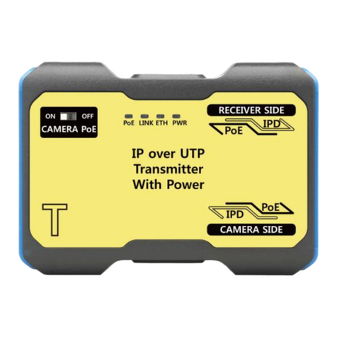
SeeEyes SC-VCD0001A User manual

VIDEO-DATA TRANSMISSION OVER SINGLE COAX CABLE
SC-VCD0001A(SC-VTD0001A + SC-VRD0001A)
User's Manual
SC-VTD0001A
SC-VRD0001A

1
Precaution and Safety Guidelines
Thank you for purchasing our product.
Please read this manual carefully and fully understand the portions of the
installation and operation instructions prior to installing and using the product.
Should you have any part of them not understandable or if you have any
problem during your installation or in using it, please contact us.
Reproduction of this instruction or any part thereof without permission is strictly
prohibited.
You must read the precautions required for safe operation prior to using it and
operate it correctly.
Please understand that the contents of this operating instruction may differ
slightly due to functional improvement of a product and based on the
specification chosen by the user.
You can use this product easier and more conveniently if you use the function of
the product only after reading this operating instruction carefully.
CAUTION
RISK OF ELECTRIC SHOCK
DO NOT OPEN
CAUTION :
TO REDUCE THE RISK OF ELECTRIC SHOCK, DO NOT
REMOVE COVER. NO USER SERVICEABLE PARTS INSIDE.
REFER SERVICING TO QUALIFIED SERVICE PERSONNEL.
The lightning flash with arrowhead symbol within an
equilateral triangle, is intended to alert the user to the
presence of uninsulated “dangerous voltage” within the
product’s enclosure that may be of sufficient magnitude to
constitute a risk of electric shock to persons.
The exclamation point within an equilateral triangle is
intended to alert the user to the presence of important
operating and maintenance (servicing) instructions in the
literature accompanying the product.
※WARNING: To reduce the risk of fire or electric shock, do not expose this
apparatus to rain or moisture.

2
1. Overview
It is the new & easy way to install video surveillance system with the various
benefits such as the long distance transmission, interference isolation, CCTV
video signal + RS-485 data transmission over the typical coaxial cable.
2. Features
“Video + Data” transmission over 1 coaxial cable
Bi-directional data communication (Half Duplex, T. Block)
Various applications with bi-directional data communication
Bi-directional Input and Output of alarm signals via separated alarm
In/Out port
Long distance transmission up to MAX. 1km (with RG-6)
Saving infrastructure cost
Built-in distance level switch for optimum video quality
Installation improvement (cost saving 25~30%)
Maintaining high quality video & interference immunity
Easy installation with BNC harness
Surge & lighting protection function
AC24V/DC12V Power Input
3. Components
Please find the following equipment in your package.
4. Connection Diagram
SC-VTD0001A (Tx.) /
SC-VRD0001A (Rx.)
Adapter
User’s Manual

3
5. How to Connect and LED Indicators
5.1 Connection Port & LED Indicator of SC-VTD0001A
Please connect the SC-VTD0001A, transmitter, to the correspondent devices
as follows.
①Video Input: connect to the video output port of the camera (BNC-F)
②RS-485: connect to the PTZ control output of the camera
③Alarm: when transmitting alarm signals from external device
④Emergency Siren: when using emergency siren from external device
⑤Video Output: connect to the receiver via the coaxial cable
⑥LED indicator:
- Green: it flickers when it transmits the data
- Yellow: it turns on when the power is on and it flickers when it
receives the data.
⑦Power input: both 12VDC and 24VAC input are available. Please note that
there is no +/- in the power input port.
Notes:
Please do not connect in parallel the RS-485 terminals of the transmitter
(SC-VTD0001A). Please use one transmitter for each receiver.
The alarm signal is transmitted bi-directionally. The alarm signal from the
transmitter operates Photo MOS Relay (60V/0.5A) at the receiver and
provides the two Open/Shorts at Output port.
The reverse operation is also available.
①Video In
②RS-485
⑤Video
Out
⑥LED
Indicator
③Alarm
④Siren
⑦Adapter (power input)

4
5.2 Connection Port & LED Indicator of SC-VRD0001A
Please connect the SC-VRD0001A, receiver, to the correspondent devices as
follows
①Video Input: connect to the transmitter via the coaxial cable
②DIP SW: set up the communication configuration. It is set in OFF in
default.
※DIP SW (BAUDRATE / PARITY)
Mode / SW No.
1
2
3
9600 bps / None (default)
OFF
OFF
OFF
4800 bps / None
ON
OFF
OFF
2400 bps / None
OFF
ON
OFF
1200 bps / None
ON
ON
OFF
Reserved
OFF
OFF
ON
9600 bps / Even
ON
OFF
ON
9600 bps / Odd
OFF
ON
ON
Auto detect / None
ON
ON
ON
※Resistance of the Termination
Mode / SW No.
4
Disconnected (Default)
OFF
Connected 120 OHM
ON
Notes:
Please turn the power OFF after changing the switch (SW) and then turn it ON.
The auto detection is available with 1200, 2400, 4800, 9600 only.
The size of packet should be lower than 21 bite.
③2P Terminal Block: connect the power adapter (24VAC / 12VDC)
④4P Terminal Block: 2P for alarm input, 2P for alarm output
⑤LED Indicator:
- Green: it flickers when it transmits the data
- Yellow: it turns on when the power is on and it flickers when it receives
the data.
⑥Video Output: connect to the DVR or the monitor.
⑦RS-485: connect to the PTZ controller such as camera controller
①
②
③
④
⑤
⑥
⑦

5
6. Specifications
MODEL
SC-VTD0001A (Transmitter)
Video IN
CVBS 1.0Vp-p, 75Ω Term.
Transmission Bandwidth
8MHz
Data LED
Tx: Green/ Rx: Yellow
Transmission Distance
Max. 1 km (with RG-6)
Connection Port
Video IN: BNC-F
Video OUT: BNC-F
DATA: RS-485/ Half Duplex, T. Block
Alarm In/Out:
Input 1CH/ Output 1CH
Power
AC 24V, DC12V/ 200mA
Temperature/Humidity
-10℃~ +50℃/ 0 ~ 80%
Case Body / Weight
Aluminum / 130g
Dimension (mm)
75(W) ⅹ60(H) ⅹ25(D)
MODEL
SC-VRD0001A (Receiver)
Video Out
CVBS 1.0Vp-p, 75Ω Term.
Power
AC 24V, DC12V/ 200mA
Data LED
Tx: Green/ Rx: Yellow
Transmission Distance
Auto Adjustment
Connection Port
Video IN: BNC-F
Video OUT: BNC-M Harness (60cm)
DATA: RS-485/ Half Duplex, T. Block
Alarm In/Out:
Input 1CH/ Output 1CH
Temperature/Humidity
-10℃~ +50℃/ 0 ~ 80%
Case Body / Weight
Aluminum / 140g
Dimension (mm)
75(W) ⅹ60(H) ⅹ25(D)
7. Precautions
Please turn the power OFF prior to the installation of the device.
The data error can be occurred where the installation circumstances are
harsh enough such as the higher voltage, container belts, etc.
Do not install or use these units in a humid, hot or hazardous explosive
environment without suitable and adequate protection.
Do no expose these units to magnetic materials, high frequency radio
waves.
Avoid exposing the units to direct sunlight or into an unstable environment.
Don’t drop the product or subject it to shock.
Don’t modify or disassemble the product.
The installation should be made by a qualified service person and should
conform to all local codes.
The transmission cable has to be used “Standard Coaxial Cable such as RG-
59, RG-6, RG-11, etc.” only. Please use BNC connector when connecting
the coaxial cable to the transmitter and the receiver units.
If there is any malfunction in the device, please contact your distributor
immediately.

6
8. Warranty Certificate
This product has passed thorough quality control and test, and if
this gets broken during normal use, we provide 12 months
warranty service.
Model No.
Serial No.
Distributor
Date you purchased
Place you purchased
Warranty Period
One (1) year from the date of purchase
Purchaser
Name
Address
•Please check this warranty indication first.
•Please contact your distributor after checking out any defect in
the products.
•The standard for repairing, replacement or reimbursement
follows Customer.
•Warranty content any defect under normal use within the
warranty service period we give you free repair service
according to the warranty certificate.
•We charge you with the fee of parts and service despite of free
warranty service period. Any breakage made without care such
as:
- Breakage or trouble made by natural disaster.
- Breakage or trouble made by breaking the product guide
or manual.
- Breakage or trouble made by wrong power voltage or
frequency.
- When you want to reassemble for full system or replace
parts within warranty service period.
- When unauthorized person modified or made damage on
the product trying to repair it.
•Please note that we don’t support the breakage after warranty
service period is expired. If the customer wants to get it
repaired, we charge them with the fee.
•The specification is subject to change without prior notice for
quality improvement.

7
S
Se
ee
eE
Ey
ye
es
s
C
Co
o.
.,
,L
Lt
td
d
i
is
s
t
th
he
e
N
Ne
ew
w
C
Co
or
rp
po
or
ra
at
te
e
N
Na
am
me
e
o
of
f
S
Sa
am
ms
su
un
ng
g
C
CC
CT
TV
V
S
Se
er
rv
vi
ic
ce
e
C
Co
o.
.,
,L
Lt
td
d
S
Se
ee
eE
Ey
ye
es
s
C
Co
o.
.,
,L
Lt
td
d
#
#5
50
02
2~
~5
50
06
6,
,
S
Su
un
ni
il
l
T
Te
ec
ch
hn
no
op
pi
ia
a,
,
4
44
40
0,
,
S
Sa
an
ng
gd
da
ae
ew
wo
on
n-
-D
Do
on
ng
g,
,
J
Ju
un
ng
gw
wo
on
n-
-G
Gu
u,
,
S
Su
un
ng
gn
na
am
m-
-S
Si
i,
,
G
Gy
ye
eo
on
ng
gg
gi
i-
-D
Do
o,
,
K
Ko
or
re
ea
a
T
TE
EL
L
:
:
+
+8
82
2-
-(
(0
0)
)3
31
1-
-7
77
77
7-
-3
35
50
08
8
F
FA
AX
X
:
:
+
+8
82
2-
-(
(0
0)
)3
31
1-
-7
77
77
7-
-3
35
51
12
2
E
EM
MA
AI
IL
L
:
:
o
ov
ve
er
rs
se
ea
as
s@
@s
ss
sc
cc
ct
tv
v.
.c
co
om
m
h
ht
tt
tp
p:
:/
//
/w
ww
ww
w.
.s
ss
sc
cc
ct
tv
v.
.c
co
om
m/
/e
en
ng
g
Table of contents
Other SeeEyes Receiver manuals
