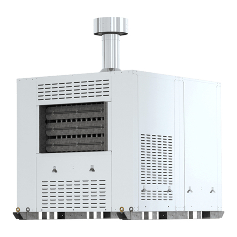
SEELEY INTERNATIONAL AIRA DU SD Series User manual

INSTALLATION AND OPERATION
DU SD SERIES HEATER
OR MODELS
Original English Instructions
AMI115-A


DU/SD SERIES INSTALL OPERATION MAINTENANCE MANUAL |1
SAFETY
1.0 Introduction 3
1.1 General Safety Information 3
1.1.1 Handling The Unit 3
1.1.2 Positioning The Heater 3
1.1.3 Combustibles 3
1.1.4 Wiring Electrical 3
1.1.5 Occupational Health And Safety 4
1.1.6 Gas Piping 4
1.1.7 Commissioning, Recommissioning, Decommissioning 4
1.1.8 Operational Safety 4
1.1.9 Gas Compliance 4
1.1.10 Safety Points To Consider 4
GENERAL INFORMATION
2.1 Unit Overview 6
2.2 Equipment Receipt 6
2.3 Factory Unit Test 6
2.4.1 Unit And Component Identication 7
2.4.2 Construction 7
2.4.3 Blower 7
2.4.4 Fan Motors 8
2.4.5 Pulleys 8
2.4.6 Dampers 8
2.4.7 Electrical Control And Connection 8
INSTALLATION INFORMATION
3.0 Installation Information 9
3.1 Model Variations And Dimensions 10
3.1.1 Dimensions - Single Exchanger No Blower DU / SD 10
3.1.2 Dimensions - Single Exchanger With Blower DU / SD 11
3.1.3 Dimensions - Dual Exchanger No Blower DU / SD 12
3.1.4 Dimensions - Dual Exchanger With Blower DU / SD 13
3.2 Installation 14
3.2.1 Location 14
3.2.2 Clearance Around Unit 14
3.2.3 Plant Room 15
3.2.4 Weight And Location 15
3.2.5 Lifting 16
3.2.6 Positioning And Securing 16
3.2.7 Duct Connections 17
3.2.8 Flue Connections 17
3.3 Electrical Connections 18
3.3.1 Electrical Supply 18
3.3.2 User Control Conguration Options 19
3.3.3 Blower / Fan Setup 19
3.3.4 Electrical Dierences For Dual Heat Exchangers 19
3.4 Gas Connections 19
3.4.1 Gas Supply 19
3.4.2 LPG 20
3.4.3 Gas Supply For Dual Heat Exchangers 20
3.4.4 Gas Train Information 20
3.4.5 Gas Pressure Valve 21
3.4.6 Operating Pressure Of The Gas Valve 22
3.4.7 Setting Gas Valve Pressure 22
3.4.8 Setting The Modulating Valve Motor 23
3.4.9 Pilot Injector Setup 24
3.4.10 Aeration Plates 24
COMMISSIONING INFORMATION
4.1 Unit Details 25
4.2 General Installation Check 25
4.3 Electrical Checks 25
4.3.1 Electrical Installation Checks 25
4.3.2 Blower Box Checks 25
4.4 Gas Checks 26
4.4 1 Incoming Gas Supply Checks 26
4.4.2 Gas Train Check 26
4.4.3 Setting The Modulating Valve Motor 27
4.4.4 Modulating Motor Operational Check 27
4.5 Setting Controls 27
4.5.1 High Limit Control 27
4.5.2 Thermostat And User Controls 28
4.5.3 RLU Screens 28
4.6 Flow Adjustment Through Lever And Damper Blades 29
4.7 General Operation 30
4.8 Setting Unit Functional Parameters 31
4.9 Commissioning Results 31
OPERATING INSTRUCTIONS
5.1 Startup - Wall Switch Units To Provide Heat 32
5.2 Startup - Wall Switch Units To Provide Ventilation 32
5.3 Shutdown - Wall Switch Units Providing Heat 32
5.4 Shutdown - Wall Switch Units Providing Ventilation 32
5.5 BMS Startup And Shutdown 32
5.6 Operational Flowchart 33
5.6.1 Heating Flowchart 33
UNIT MAINTENANCE
6.0 Service And Maintenance 34
6.1 Heater Maintenance 34
6.1.1 Heater Maintenance 34
6.2 Major Service/Component Replacement Process 35
6.2.1 Electrical Components 35
6.2.1.1 Electrical Wiring 35
6.2.1.2 Isolator Fitted And Operational 35
6.2.1.3 Single Or 3 Phase Power Test 35
6.2.1.4 Overtemp Control Switch 35
6.2.1.5 Thermostat Fitted And Operational 35
6.2.1.6 Fan And Motor 35
6.2.1.7 Belts 36
6.2.1.8 Pulleys 36
6.2.1.9 Fan Direction 36
6.2.2 Gas Components 36
6.2.2.1 Gas Controls 36
6.2.2.2 Gas Connection Visual Inspection 36
6.2.2.3 Gas Isolation Fitted 37
6.2.2.4 Gas Supply Pressure 37
6.2.2.5 Gas Burner Pressure (High/Low) 37
6.2.2.6 Gas Injectors 37
6.2.2.7 Draft Diverters 37
6.2.2.8 Pilot Assembly 37
6.2.2.8.1 Cleaning Pilot Burner: 37
6.2.2.9 Leaving Air Sensor 38
6.2.3 Casing Components 38
6.2.3.1 Weatherproof Casing Condition 38
6.2.3.2 Duct Condition 38
6.2.3.3 General Installation 38
6.2.3.4 Access To Unit 38
6.2.3.5 Maintenance Records 38
6.3 Fault Finding 39
6.3.1 Fault Finding Heater 39
6.4 Replacement Parts List 40
APPENDIX
A: AGA Type B Information 41
B: Electrical Information 42
C: Gas Train Information 43
D: Commissioning Report 45
E: Temperature Rise Over Heat Exchanger
E1 - Leaving Air Temp Exceeds 40°C 47
E2 - Set Temperature Cannot Be Reached 47
E3 - Set Temperature Achieved, Modulating Controls Temp 48
F: Maintenance
F1 - Maintenance Schedule 49
F2 - Monthly Maintenance Check 50
F3 - Maintenance Checklist 51
G: Warranty Information
G1 - How To Register Your Product Warranty 53
G2 - Warranty Terms And Information 54
H: Release Information 57
CONTENTS

2 |

DU/SD SERIES INSTALL OPERATION MAINTENANCE MANUAL |3
1.0 INTRODUCTION
This Manual is for use with a Seeley International manufactured AIRA DU/SD Heater OR Model units. This manual is
updated without notication and it is the installer and customers responsibility to ensure the latest version is used. This
Manual is intended to assist in the Installation, Commissioning and Service of Seeley International manufactured DU/
SD units and DOES NOT take precedence over any Australian Standards or legislation.
This book should be retained with the unit or made easily accessible to installation and maintenance personnel.
AIRA DU/SD units are a natural draft gas red appliance, capable of supplying indirect gas heating and direct air
ventilation. DU/SD units are produced in 8 dierent capacities to suit a wide variety of installation requirements. All
Natural Gas AIRA units are certied as a Type A appliance, LPG units require a Type B certication with the exception
of DU12, DU16 and SD40 which are Type A LPG certied.
1.1 GENERAL SAFETY INFORMATION
THIS INDIRECT GAS HEATER IS TO BE INSTALLED BY AN AUTHORISED PERSON ONLY
DO NOT Operate this appliance before reading the manual.
DO NOT Place articles on or against this appliance.
DO NOT Use or store ammable materials within 1200mm of this appliance.
DO NOT Operate this appliance with panels, covers or guards removed.
DO NOT Spray aerosols in the vicinity of this appliance while it is in operation.
DO NOT Remove markings and or labels from the unit.
DO NOT Remove warning labels from the unit.
These AIRA DU/SD units must be installed in accordance with these instructions, local plumbing regulations, municipal
building codes, electrical wiring regulations, Australian Standard AS/NZS 5601 Gas Installations and any other relevant
statutory requirements.
Employers and Employees Responsibility
The installation and maintenance of gas ducted
heating units, particularly at height, has the potential
to create Occupational Health and Safety (OH&S)
issues for those involved. Installers are advised to
ensure they are familiar with relevant State and Federal
legislation, such as Acts, Regulations, approved
Codes of Practice and Australian Standards, which
oer practical guidance on these health and safety
issues. Compliance with these regulations will require
appropriate work practices, equipment, training and
qualication of workers. Seeley International provides
the following information as a guide to contractors and
employees to assist in minimising risk.
Risk Assessment
A risk assessment of all hazardous tasks is required under
legislation. A risk assessment is an essential element that
should be conducted before the commencement of work,
to identify and eliminate the risk of falls and other risks, or
to minimise these risks by implementing control measures.
This does not need to be a complicated process - it is a
matter of assessing the job to be done and considering
what actions are necessary so the person doing the job
does not injure themselves.
This should be considered in terms of:
• What are the chances of an incident occurring?
• What could the possible consequences be?
• What can be done to reduce, or better still, eliminate
the risk?
1.1.1 Handling the Unit
Heaters are provided with external lifting points and should be moved by appropriately qualied personnel for the type
of equipment used to move the unit. i.e Rigger, crane operator and fork lift driver. The heater must remain upright at all
times.
1.1.2 Positioning the Heater
The unit should be installed so that it is level. Allow 1200mm clearance at the front and control side of the unit and
500mm on the bottom (for hung units), top, and other side. Air intake to the unit should not be restricted in any manner.
Approval should be sought by Seeley for any installation encroaching on these limits. No modications shall be made
to the unit.
1.1.3 Combustibles
The heater should not be installed in contact with combustible materials. Radiant heat from the unit must also be
considered. Combustibles should not be stored within 1200mm of the unit.
1.1.4 Wiring Electrical
Connections must be in accordance with all relevant Australian Standards and applicable State regulations.
SAFETY

4 |
1.1.5 Occupational Health and Safety
Only safe working practices shall be employed when working on gas installations. The process of installing gas
appliances shall take into consideration relevant OH&S requirements. There requirements pertain to all aspects
of access, installation, operation and maintenance. Persons installing gas appliances shall be aware of their
responsibilities and qualied in accordance with local OH&S requirements. Precautions shall be taken to avoid any
electrical hazards present in the gas installation.
1.1.6 Gas Piping
Gas piping should be sized adequately, located, supported and protected in accordance with the Installation Standard
AS/NZS 5601.
1.1.7 Commissioning, Recommissioning and Decommissioning
Every gas installation shall be commissioned according to the instructions in Section 4 of this Manual prior to use to
ensure safe start and operation of the unit and shall include checks of safety and operating control.
Following maintenance work on any part of the unit, the aected part of the installation shall be re-commissioned by
checking to ensure safe start-up and operation.
After a maintenance shutdown, isolation of the unit or interruption to the gas or electrical supply an appropriately
qualied person shall conduct start up checks to conrm safe operation.
When a unit is being decommissioned it shall be physically disconnected from the gas supply, purged and sealed.
Where possible components should be recycled, apart from the gas train and valves which should be disposed of in
accordance with government regulations.
1.1.8 Operational Safety
AIRA DU/SD Heaters must not be operated until the unit has been commissioned by qualied persons. The unit should
not be operated if any safeguards, panels or controls have been removed, damaged or bypassed.
If the unit is not operating as intended turn o the unit at the wall switch/BMS and then isolate the power and gas
supply. The unit should remain isolated until a qualied service technician has inspected the unit and resolved any
issues.
1.1.9 Gas Compliance
Aira Heater units are not all Type A certied. For those NOT Type A certied a Type B certication is required. AS/NZS
5601.1 states that the requirements of the standard are to be used in conjunction with, but do not take precedence
over, statutory requirements that may apply in any area. Where no requirement is given, good practice shall apply.
Type A Compliant
Natural Gas LPG
DU12 YES YES
DU16 YES YES
SD26 YES YES
SD30 YES YES
SD35 YES YES
SD40 YES YES
Table 1: Type A Compliance
1.1.10 Safety Points to Consider
• What is the best and safest access to the roof and/or work areas?
• If a worker is alone, who knows they are there and if they get into diculty, how can they summon help? (Call
someone on the ground? Mobile phone? etc.)
• Has the roof section or structure been assessed to ensure that it can withstand the load of the appliance and
workers.
• Does the worker have appropriate foot wear? (Flat sole jogger type is advisable.)
• Are all power cables / extension leads safe and appropriately rated?
• Are all ladders, tools and equipment suitable in good condition?
• Where ladders are to be used, is there a rm, stable base for them to stand on? Can they be tied or secured in
some way at the top? Is the top of the ladder clear of electricity supply cables?
• Is there a roof anchor to attach a harness and lanyard to? If so, instruction should be issued for the use of an
approved harness or only suitably trained people used.
SAFETY

DU/SD SERIES INSTALL OPERATION MAINTENANCE MANUAL |5
• Are all tools and materials being used, prevented from slipping and falling onto a person at ground level? Is the
area below the work area suitably protected to prevent persons walking in this area?
• Does the work schedule take into account weather conditions, allowing for work to be suspended in high winds,
thunder storms/lightning or other types of weather giving wet, slippery surfaces?
• Is there an on-going safety check system of harnesses, ropes, ladders and access/lifting equipment and where
they exist on roofs, anchor points before the commencement of work?
• Is there a system which prevents employees from working on roofs if they are unwell or under the inuence of
drugs or alcohol?
• Are there any special conditions to consider i.e. excessive roof pitch, limited ground area, fragile roof, electrical
power lines?
• Is the person conducting the installation and maintenance appropriately qualied and familiar with local authority
and Australian Standards.
SAFETY

6 |
2.1 UNIT OVERVIEW
AIRA DU/SD units are natural draft, indirect gas red heaters. The standard control system is congured for integration
with Building Management Systems (BMS). An optional standalone control system utilising a room thermostat to
control heat demand from the DU/SD is also available. Manual AM006 provides a comprehensive control and wiring
information package.
Gas rate modulation is provided in order to maintain a more consistent room temperature. Once the room set
temperature is reached the unit will cease heating. Consequently, as the room temperature falls below the set point the
unit will automatically resume heating.
DU/SD can be tted with an optional blower box, housing a single or dual centrifugal fans and electric motor. Alternately
the DU/SD can be installed in duct work with a 3rd party blower or evaporative cooler which is designed to provide
suitable airow to the heater.
Units are supplied with a ue suitable for external installation. Units installed in a utility room must be externally ued to
atmosphere and in accordance with the Australian Standards and local regulations for ue installations of this type. The
units are natural draft and CAN NOT be installed in a negative pressure environment.
Commissioning can be provided by Seeley International otherwise for all type A appliances an experienced Type A
installer is recommended. Type B units will require independent type B certication to local legislation.
2.2 EQUIPMENT RECEIPT
Inspect the unit for any damage caused in transit. Any such damage must be immediately reported to the shipper of the
goods.
The unit has been factory tested to check for correct operation of all components. If any part is obviously missing or
damaged, notify the supplier immediately.
Check the appliance to ensure that the SU/DU unit that has been supplied will operate with the available gas supply,
i.e. Natural or LPG gas.
2.3 FACTORY UNIT TEST
All AIRA heaters are given a factory unit test which covers the function test and checks of the safety system including;
• Blower/fan operation (if tted)
• Gas ignition and ame detection
• Gas valve modulation (if tted)
• Operation of the High Limit Safety Switch
• Functional test for all units
GENERAL INFORMATION

DU/SD SERIES INSTALL OPERATION MAINTENANCE MANUAL |7
2.4 TECHNICAL SPECIFICATION
2.4.1 Unit and Component Identication
GENERAL INFORMATION
2.4.2 Construction
• The frame is a galvanised steel body with stainless steel burners and heat exchanger with draft diverter. Flues, ue
cowls and external cabinet are marine grade aluminium.
• Aira units are designed to be used with Aira ues and ue cowls. Fitment of third-party ues and ue cowls must be
approved by an accredited ue designer.
• Units are standard with an external casing except F units. Open frame units for dual heat exchangers can supplied
without a cabinet but to OEM customers only.
2.4.3 Blower
• The standard blower is forward curved and constructed from steel. Units not installed in ductwork are typically
optioned with an axial fan due to the low pressure drop.
• Blower housings are powder coated steel as standard.
Table 2: DU SD Unit Technical Data
MODEL: DU12 DU16 SD26 SD30 SD35 SD40 SD51 SD60 SD70
CONFIGURATION
Type SINGLE HEAT EXCHANGER DUAL HEAT EXCHANGER
HEATING
PERFORMANCE
Airow 28C
Temp Rise (L/s) 840 1118 1784 2100 2454 2785 3568 4200 4908
Airow 11C
Temp Rise (L/s) 2098 2800 4460 5240 6316 6985 8920 10478 12272
Input NG
(LPG) (MJ/hr) 138 (127) 184 (169) 246 (249) 287 (290) 349 (349) 390 (422) 2x 246
(249)
2x 287
(290)
2x 349
(349)
Output NG
(LPG) (kW) 29 (26) 38 (35) 51 (44) 60 (60) 73 (62) 88 (81) 2x 51 (44) 2x 60 (60) 2x 73 (62)
SERVICES
Electrical
Voltage
V/Ph/Hz
240/1/50
and
415/3/50
240/1/50
and
415/3/50
240/1/50
and
415/3/50
240/1/50
and
415/3/50
240/1/50
and
415/3/50
240/1/50
and
415/3/50
240/1/50
and
415/3/50
240/1/50
and
415/3/50
240/1/50
and
415/3/50
Max Power 1.3 1.3 2.4 3.2 4.2 5.2 4.6 6.2 8.2
Duct
Connections
Orientation
(mm)
Side
Discharge
Side
Discharge
Side
Discharge
Side
Discharge
Side
Discharge
Side
Discharge
Side
Discharge
Side
Discharge
Side
Discharge
CONTROLLER
Type Standard BMS
Interface
BMS
Interface
BMS
Interface
BMS
Interface
BMS
Interface
BMS
Interface
BMS
Interface
BMS
Interface
BMS
Interface
Type Optional Wall
Switch
Wall
Switch
Wall
Switch
Wall
Switch
Wall
Switch
Wall
Switch
Wall
Switch
Wall
Switch
Wall
Switch
Voltage V/Ph/Hz
BMS
(Customer
Supplied)
BMS
(Customer
Supplied)
BMS
(Customer
Supplied)
BMS
(Customer
Supplied)
BMS
(Customer
Supplied)
BMS
(Customer
Supplied)
BMS
(Customer
Supplied)
BMS
(Customer
Supplied)
BMS
(Customer
Supplied)
FAN
Type Blower Blower Blower Blower Blower Blower Blower Blower Blower
Diameter Inch 12 12 15 15 15 x 11
Dual
15 x 11
Dual 2 x 15 2 x 15 2 x 15 x 11
Dual
Capacity High High High High High High High High High
MOTOR
Type CS & R CS & R 3 Phase 3 Phase 3 Phase 3 Phase 3 Phase 3 Phase 3 Phase
Speed RPM 1440 1440 1440 1440 1440 1440 1440 1440 1440
Output (kW) 1.1 1.1 2.2 3.0 4.0 5.5 2 x 2.2 2 x 3.0 2 x 4.0
Rated (A) 7.1 7.1 4.9 6.4 8.4 11.2 4.9 / motor 6.4 / motor 8.4 / motor
Frame Size B56 B56 100L 100L 100L 100L 100L 100L 100L
Rating IP 21 21 55 55 55 55 55 55 55
GAS SUPPLY
LPG (Propane)
Maximum (kPa) 3.5 3.5 3.5 3.5 3.5 3.5 3.5 3.5 3.5
Minimum (kPa) 2.74 2.74 2.74 2.74 2.74 2.74 2.74 2.74 2.74
GAS SUPPLY
NG
Maximum (kPa) 3.5 3.5 3.5 3.5 3.5 3.5 3.5 3.5 3.5
Minimum (kPa) 1.12 1.12 1.12 1.12 1.12 1.12 1.12 1.12 1.12
TEST POINT LPG
(Propane)
High (kPa) 2.5 2.5 2.5 2.5 2.3 2.5 2.5 2.5 2.3
Low (kPa) 0.875 0.875 0.875 0.875 0.875 0.875 0.875 0.875 0.875
TEST POINT NG
High (kPa) 0.875 0.875 0.72 0.72 0.72 0.72 0.72 0.72 0.72
Low (kPa) 0.30 0.30 0.30 0.30 0.30 0.30 0.30 0.30 0.30
GAS SUPPLY SIZE
(inch) 3/4 3/4 3/4 3/4 3/4 3/4 3/4 3/4 3/4
INJECTORS/BURNERS
Number 6 8 12 14 17 19 24 28 34
DIMENSIONS
Shipping
(Blower) (mm)
2100 Long
1200 Wide
1500 High
2100 Long
1200 Wide
1500 High
2500 Long
1800 Wide
1820 High
2500 Long
1800 Wide
1820 High
2500 Long
1800 Wide
2170 High
2500 Long
1800 Wide
2170 High
3000 Long
1900 Wide
1805 High
3000 Long
1900 Wide
1805 High
3700 Long
2350 Wide
1805 High
Shipping
(No Blower) (mm)
2100 Long
1200 Wide
1500 High
2100 Long
1200 Wide
1500 High
2100 Long
1200 Wide
1820 High
2100 Long
1200 Wide
1820 High
2100 Long
1200 Wide
2170 High
2100 Long
1200 Wide
2170 High
3000 Long
1900 Wide
1805 High
3000 Long
1900 Wide
1805 High
3700 Long
2350 Wide
1805 High
Service
Clearance
All Sides
(mm) 1200 1200 1200 1200 1200 1200 1200 1200 1200

8 |
2.4.4 Fan Motors
• Fan motors are mounted externally to the blower and connect via a set of pulleys.
• All units are available at order with 2 dierent motor power capacity to meet ow and pressure requirements. Units
may be tted with a larger motor at additional cost. Contact Seeley international for further advice.
• Axial fans are specied for the F conguration and designed to be installed indoors generally as an air curtain.
2.4.5 Pulleys
• Upon order the customer will be given the options of one of three pulley kits to meet their ow and pressure
requirements.
• Variations in external pressure drop outside of the standard product range require pulley and belt combinations to
be supplied by the customer.
• All pulleys are of steel construction with taper lock mounting.
2.4.6 Dampers
• All units are supplied with adjustable galvanised steel dampeners with preset positions to be set by the installer.
• Axial fan units use the dampers to adjust air throw in addition to heat rise.
2.4.7 Electrical Control and Connection
• All units are equipped with an electrical control box which controls the Gas Pilot, Main Valve, Modulating Valve
(when installed) and Blower operation.
• All units are tted with High Limit Safety Switches on the Air Inlet and Outlet Side and an Automatic Fan Switch to
prevent overheating. Caution: Automatic fan switch will cause the fan to operate without notice once the unit is
powered down and heat soak takes place.
GENERAL INFORMATION

DU/SD SERIES INSTALL OPERATION MAINTENANCE MANUAL |9
INSTALLATION INFORMATION
3.0 INSTALLATION INFORMATION
The supplied units are to be installed in accordance to this manual, relevant local standards, acts and regulations.
The space in which the DU/SD unit is installed shall be ventilated to the extent required to ensure safe and eective
operation. The unit shall also not be installed in a location that will aect the operation of mechanical devices used to
displace air either within the same space or within a connected space.
DU/SD units shall be installed so that adjacent combustible surfaces are protected from damage resulting from thermal
eects of their operation.
If there are existing gas appliances the it shall be conrmed that there is adequate capacity before connecting the DU/
SD unit.
Isolation of the gas and electrical supplies to the units shall be accessible and identiable at all times.

10 |
G
B
C
K
L
C
B
H
A
I
J
E
C
D
113113
F
B
A
113 113
EQ EQ
111.2 111.2
INSTALLATION INFORMATION
Dimensions are in mm.
G
B
C
K
L
C
B
H
A
I
J
E
C
D
113113
F
B
A
113 113
EQ EQ
111.2 111.2
G
B
C
K
L
C
B
H
A
I
J
E
C
D
113113
F
B
A
113 113
EQ EQ
111.2 111.2
SINGLE HEAT EXCHANGER NO BLOWER
ISOMETRIC
TOP
REAR SIDE
BOTTOM
AMI138-A ISO AMI138-A TOP
AMI138-A REAR
AMI138-A SIDE
AMI138-A BOTTOM
G
B
C
K
L
C
B
H
A
I
J
E
C
D
113113
F
B
A
113 113
EQ EQ
111.2 111.2
G
B
C
K
L
C
B
H
A
I
J
E
C
D
113113
F
B
A
113 113
EQ EQ
111.2 111.2
FRONT
AMI138-A FRONT
G
B
C
K
L
C
B
H
A
I
J
E
C
D
113113
F
B
A
113 113
EQ EQ
111.2 111.2
113113
B
A
B
K
H
J
C
IF
E
A
D
C
B
C
112
EQ EQ
113
112
G
DIM DU12 DU16 SD26 SD30 SD35 SD40
A920 920 920 920 920 920
B995 995 1556 1556 1890 1890
C1253 1252 1570 1570 1918 1918
D697 712 705 753 569 582
EVaries based on installation requirements
F510 510 728 728 987 987
G457 596 865 1003 1208 1346
H150 175 200 250 250 250
I455 455 525 525 525 525
J40 40 35 35 35 35
K505 505 790 790 955 955
L550 550 795 795 1080 1080
Gas Inlet 370 370 580 580 840 840
3.1.1 UNIT DIMENSIONS - SINGLE HEAT EXCHANGER NO BLOWER DU / SD
113
L
3.1 MODEL VARIATIONS AND DIMENSIONS
Figure 1A: DU SD Units

DU/SD SERIES INSTALL OPERATION MAINTENANCE MANUAL |11
INSTALLATION INFORMATION
Dimensions are in mm.
B
C
B
G
H
C
B
A
113 113
EQ EQ
112.4 112.4
A
D
E
113 113
F
I
J
B
C
B
G
H
C
B
A
113 113
EQ EQ
112.4 112.4
A
D
E
113 113
F
I
J
SINGLE HEAT EXCHANGER WITH BLOWER DU / SD
ISOMETRIC
TOP
REAR SIDE
BOTTOM
AMI139-A ISO AMI139-A TOP
AMI139-A REAR AMI139-A SIDE
AMI139-A BOTTOM
B
C
B
G
H
C
B
A
113 113
EQ EQ
112.4 112.4
A
D
E
113 113
F
I
J
B
C
B
G
H
C
B
A
113 113
EQ EQ
112.4 112.4
A
D
E
113 113
F
I
J
B
C
B
G
H
C
B
A
113 113
EQ EQ
112.4 112.4
A
D
E
113 113
F
I
J
FRONT
AMI139-A FRONT
B
C
B
G
H
C
B
A
113 113
EQ EQ
112.4 112.4
A
D
E
113 113
F
I
J
113113
B
A
AD
J
I
F
E
B
G
C
B
C
112 112
H
EQ EQ
113 113
DIM DU12 DU16 SD26 SD30 SD35 SD40
A1835 1835 1835 1835 1835 1835
B995 995 1556 1556 1890 1890
C1253 1252 1570 1570 1918 1918
D697 712 705 753 569 582
EVaries based on installation requirements
F510 510 728 728 987 987
G457 596 865 1003 1208 1346
H150 150 200 250 250 250
I455 455 525 525 525 525
J40 40 35 35 35 35
K505 505 790 790 955 955
L550 550 795 795 1080 1080
Gas Inlet 370 370 580 580 840 840
3.1.2 UNIT DIMENSIONS - SINGLE HEAT EXCHANGER WITH BLOWER DU / SD
Figure 1B: DU SD Units

12 |
G G
K K
C
A
B
L
M
L
D
50
55
50
55
49
A
H
J J
E
I
I
F
NN
C
G G
K K
C
A
B
L
M
L
D
50
55
50
55
49
A
H
J J
E
I
I
F
NN
C
G G
K K
C
A
B
L
M
L
D
50
55
50
55
49
A
H
J J
E
I
I
F
NN
C
G G
K K
C
A
B
L
M
L
D
50
55
50
55
49
A
H
J J
E
I
I
F
NN
C
Dimensions are in mm.
DUAL HEAT EXCHANGER NO BLOWER TOP
REAR SIDE
AMI140-A TOP
AMI140-A REAR AMI140-A SIDE
FRONT
AMI140-A FRONT
K
A
C
A
ML L
B
D
G G K
N N
C
H
JJ
F I
I
E
3.1.3 UNIT DIMENSIONS - DUAL HEAT EXCHANGER NO BLOWER DU / SD
DIM SD51 SD60 SD70
A1025 1055 775
B2730 2730 3135
C1555 1555 1555
D895 925 590
EVaries based on installation requirements
F630 630 630
G800 935 1145
H200 250 250
I505 505 505
J35 35 35
K510 375 370
L905 840 940
M910 1045 1255
N800 935 1145
Gas Inlet 580 580 580
INSTALLATION INFORMATION
Figure 1C: DU SD Units

DU/SD SERIES INSTALL OPERATION MAINTENANCE MANUAL |13
J J
D
A
I
F
B
C
L
E
M
L
I
K
G G
K
H
C
B
N N
I
B
A
55
49 49 49
5050
55
INSTALLATION INFORMATION
J J
D
A
I
F
B
C
L
E
M L
I
K
G G
K
H
C
B
N N
I
B
A
55
49 49 49
5050
55
Dimensions are in mm.
DUAL HEAT EXCHANGER WITH BLOWER DU / SD
ISOMETRIC
TOP
REAR SIDE
BOTTOMFRONT
J J
D
A
I
F
B
C
L
E
M
L
I
K
G G
K
H
C
B
N N
I
B
A
55
49 49 49
5050
55
J J
D
A
I
F
B
C
L
E
M
L
I
K
G G
K
H
C
B
N N
I
B
A
55
49 49 49
5050
55
J J
D
A
I
F
B
C
L
E
M
L
I
K
G G
K
H
C
B
N N
I
B
A
55
49 49 49
5050
55
J J
D
A
I
F
B
C
L
E
M
L
I
K
G G
K
H
C
B
N N
I
B
A
55
49 49 49
5050
55
NN
B
B
L LM
H
K KGG
C
I
I
C
E
JJ
IF
A
D
55 55
49 49 49
5050
AMI141-A ISO AMI141-A TOP
AMI141-A REAR
AMI141-A FRONT
AMI141-A BOTTOM
AMI141-A SIDE
3.1.4 UNIT DIMENSIONS - DUAL HEAT EXCHANGER WITH BLOWER DU / SD
DIM SD51 SD60 SD70
A 1555 1555 1555
B2730 2730 3135
C1555 1555 1555
D895 925 590
EVaries based on installation requirements
F630 630 630
G800 935 1145
H200 250 250
I505 505 505
J35 35 35
K510 375 370
L905 840 940
M910 1045 1255
N800 935 1145
Gas Inlet 580 580 580
A
B
Figure 1D: DU SD Units

14 |
AMI043-A
Figure 2: Service Clearance around Unit
INSTALLATION INFORMATION
3.2 INSTALLATION
The following recommendations are not intended to supplant or take precedence over relevant ocial regulations. AIRA
DU / SD units are designed essentially as a roof top or external ground mount unit.
3.2.1 Location
This equipment is not designed for long and complex air distribution ductwork and as such the unit should be located
as close as practicable to the points of air distribution. Depending on large volumes of 100% fresh air, care must
be taken to locate the unit clear of kitchen exhausts, heavy vehicle trac, industrial fume discharge etc. that may
allow odour or fume laden air to be drawn into the unit. The prime requisites for the correct location of a unit is an
unrestricted supply of clean fresh air. Units shall not be installed in an environment where negative pressure is exerted
on the unit. If the unit is installed indoors a qualied engineer shall be engaged to ensure that the unit is not subject to
negative pressure. Failure to do so may result in fatalities.
When selecting a location for the DU / SD unit the following shall be considered.
1. Will the unit be suitably protected from the eects of corrosion and/ or dust laden environments and any likelihood
of physical damage?
2. Can qualied personnel perform functional adjustments and maintenance on the unit?
3. Does the chosen location prevent a hazard to the building or structure or to the contents of the building?
4. How to minimise the risks associated with storage, use or release of hazardous or ammable substances in the
vicinity of the unit?
5. How to minimise risk of harm to persons?
6. Will the noise of the unit operating aect persons nearby? Units should be located so that quiet areas such as
bedrooms, living rooms, meetings rooms etc. are not aected for both the premises that the unit is being installed
and adjoining properties.
7. A structural engineer is to be engaged to prove that the supporting structure is suitable for a fully laden unit.
8. Ensure any skylights within 3m of the units have adequate fall protection installed.
3.2.2 Clearance Around Unit
1200mm is the recommended clearance around all sides for service access. All combustibles must be kept outside the
1200mm clearance zone
1200MM
SERVICE
ACCESS
BOTH SIDES
1200MM
UNDER
DUCTWORK
1200MM
INTAKE

DU/SD SERIES INSTALL OPERATION MAINTENANCE MANUAL |15
INSTALLATION INFORMATION
Table 7: Unit with Blower Corner Weights
Figure 3: Unit with Blower Corner Weights
D
C A
B
AMI076-A
MODEL A B C D
DU12 67kg 83kg 75kg 45kg
DU16 82kg 76kg 56kg 63kg
SD26 133kg 90kg 68kg 89kg
SD30 124kg 112kg 74kg 81kg
SD35 131kg 141kg 122kg 88kg
SD40 133kg 159kg 143kg 77kg
AMI118-A
MODEL A B C D
DU12 47kg 37kg 33kg 37kg
DU16 48kg 42kg 35kg 39kg
SD26 71kg 52kg 43kg 58kg
SD30 51kg 76kg 74kg 43kg
SD35 54kg 95kg 95kg 44kg
SD40 98kg 69kg 63kg 87kg
Figure 4: Single Unit Corner Weights
Table 6: Single Unit Corner Weights
3.2.3 Plant Room
Do not locate unit in an enclosed plant room unless sucient openings are available to ensure air pressure in the plant
room CANNOT become negative with all items in the plant room operating. Mechanical ventilation may be required.
Failure to achieve positive plant room pressure will result in gas combustion gasses being drawn into the room being
heated, presenting a health risk to any occupant. A suitably qualied engineer must be consulted when considering this
type of installation.
3.2.4 Weight and Location
For roof mounting, the building’s roof must be adequately designed to support the unit weight and any service
personnel. If in doubt a suitably qualied Civil or Structural Engineer should be engaged to conduct an assessment.
The below gures and tables list the corner weights of the units with and without blower.

16 |
3.2.6 Positioning and Securing
Small, Medium and Large cabinet units are supplied with under cabinet skids. Units are designed to be supported
along the length of the skids. Holes may be drilled into the skids to secure the unit in place. Lifting points may be
inverted and used in assisting to secure the unit. Lifting points at either end of the units are NOT to be used for
anything other than lifting the unit into place and may be removed once installation has occurred.
It is the responsibility of the installer to ensure that any platform used to support the unit is suitably designed. A suitably
qualied Civil or Structural Engineer must be engaged to conduct an assessment.
INSTALLATION INFORMATION
Figure 5: Lifting Example
AMI041-A
Figure 6: Securing Example
3.2.5 Lifting
Units are to be lifted by the points specied and designed to lift only the specic units’ dry weight. These lifting points
are suitable for either Crane or Helicopter lift with suitable spreader bars. The unit cabinet is lightweight aluminium and
at no point should the lifting slings or spreader bar contact the cabinet, failure to comply will permanently damage the
case.
Lifting point securing bolts and lifting eyes must be inspected for prior to lifting to ensure all bolts are installed, of
correct tensile strength and are correctly tensioned. If any damage is observed, lifting points and/or eyes should be
replaced.
Below is a suggested lifting arrangement. Noting that the centre of gravity should be assessed for each unit prior to
lifting by suitably qualied crane operator, rigger and dogmen. Certication of the lifting lug assembly may be obtained
by contacting Seeley International.
AMI148-A

DU/SD SERIES INSTALL OPERATION MAINTENANCE MANUAL |17
INSTALLATION INFORMATION
3.2.8 Flue Connections
Units are proved with a short section of ue which is designed to suit the heat exchanger, draft diverter and rain collar.
It is the installers responsibility to provide additional lengths and orentations of ue to ensure that the ue terminates in
a location that is compliant with AS5601.1 and local regulations and requirements. Flue cowls supplied are certied by
AGA independent of the unit, so may be suitable for use on dierent length ues in accordance with AS4566-2005 Flue
cowls – Gas Appliances.
The ue is to be secured to the spigot with sheet metal TEK type screws. If a dierent ue design is used the ue up
draft must be conrmed after appliance if started to ensure adequate ow. Flue temperatures are expected between
250 to 300 Deg C. and may require additional ue skins especially when penetration through walls, roofs, oors, etc.
Figure 7: Duct Connections
Figure 8: Flue Connections
AMI119-A
3.2.7 Duct Connections
The outlet of the unit is provided with a 40mm ange for Ductmate® or similar ductwork connection. An inspection and
service panel is located above and below the duct connection ange. Duct connection should be in a manner which
maintains panel operation without the need to remove ductwork.
Refer to the Model Variants and Dimensions section of the document for specic unit details.
G
B
C
K
L
C
B
H
A
I
J
E
C
D
113113
F
B
A
113 113
EQ EQ
111.2 111.2
AMI138-A SIDE
B
K
H
C
L
FLUE COWL
FLUE RAIN COLLAR
ROOF SPIGOT
DRAFT DIVERTOR
SPIGOT

18 |
INSTALLATION INFORMATION
Figure 9: Isolation Box Location
AMI114-A
3.3 ELECTRICAL CONNECTIONS
3.3.1 Electrical Supply
All electrical connections are to be as per AS3000. All electrical work shall be performed by a registered electrical
contractor. Aira Manual AM006, provides a comprehensive electrical connection guide including wiring congurations
for dierent control setups and wiring diagram package and should be used in conjunction with this manual.
• Electrical circuit breakers must be a minimum of a “ D curve” motor start circuit breaker.
• Electrical circuit breakers must be sized according to the total load requirements.
For Weatherproof units, the electrical connection will require a hole saw to drill through a corner panel for conduit entry.
When entering the unit:
• DO NOT run cables or conduit across the heater.
• DO NOT run the cables on the oor under the heat exchanger.
• DO NOT wire directly into the control box except for control wires as per the wiring diagram.
ISOLATION BOX
Table of contents
Other SEELEY INTERNATIONAL Heater manuals

SEELEY INTERNATIONAL
SEELEY INTERNATIONAL Convair CTH06 User manual

SEELEY INTERNATIONAL
SEELEY INTERNATIONAL Braemar Invertair SACV10D1S User manual

SEELEY INTERNATIONAL
SEELEY INTERNATIONAL DU User manual

SEELEY INTERNATIONAL
SEELEY INTERNATIONAL Braemar Ecostar TQ3 User manual

SEELEY INTERNATIONAL
SEELEY INTERNATIONAL Braemar PWF30 User manual