Seen IRIS 860 Sensor User manual

© Copyright 2021 Seen Safety Limited. IRIS 860 Installation Guide. Version 2.3 1
INSTALLATION GUIDE
SEEN IRIS 860 Sensor
SEEN IRIS 860 Cab Box
www.seensafety.com | we’ve Got Your Back

© Copyright 2021 Seen Safety Limited. IRIS 860 Installation Guide. Version 2.3 2
Contents
Before you start 3
System overview 3
Power requirements 4
Sensor mounting 5
Sensor wiring 6
Cab Box wiring 7
Cab Box Sensor Cable 9
Weather shield 10
Set-up examples 11
Internal self check function 13
Sensor maintenance 13
Trouble-shooting 14
Connecting an accessory 16
Changing the sensor settings 18
Software settings 20
Warranty 21
Specifications 22
Important warning
SEEN IRIS 860 sensors can provide collision warning
assistance to the operator but do not replace the need for
proper operator training and best practice safe operating
procedure. While IRIS 860 sensors can alert the machine
operator to a potential collision, the operator is always
fully responsible for the safe operation of the equipment.
IRIS 860 sensors do not comply with the regulatory
standards required for devices which are intended to
directly control vehicle or machine safety functions. Using
the sensor accessory port to control a vehicle or machine
function is entirely your own risk. Detection can never be
guaranteed.
IRIS 860 sensors are a CLASS I LASER PRODUCT.
Disassembly or modification of this device may result in
hazardous radiation exposure and will void the warranty.
This installation and set-up guide has been prepared with
all due care and attention, however, Seen Safety Limited
cannot be held responsible for any errors or omissions in
this guide or any consequences thereof.
Seen Safety Limited
Unit 4, 69 Kaiwharawhara Road
Wellington 6035,
New Zealand
+64 4 381 4475
www.seensafety.com
support@seensafety.com
IRIS 860 sensors and Cab Boxes require a 12–24
volt power supply. Power supplies exceeding
24 volts require a DC/DC voltage converter.

© Copyright 2021 Seen Safety Limited. IRIS 860 Installation Guide. Version 2.3 3
System overview
SEEN IRIS 860 sensors are intended for use on heavy mobile
equipment like forklifts and wheel loaders. The sensor uses
non-visible infrared laser light to detect the presence of
retroreflective material such as the retroreflective tape found
on day/night high visibility safety clothing and markers.
Each sensor has a 60º horizontal by 45º vertical field of view
and can detect retroreflective material between 0.8 and 8.0
metres from the sensor face. Detection is indicated by a loud
continuous-tone audible alert.
Sensor settings –such as the detection distance– can be pre-
set using SEEN’s free IRIS 860 setup app.
=
Buzzer
M6 mount
M6 mount
Vent
Accessory
socket
Power
socket
Back
IRIS 860 sensor
60º
45º
Before you start
Read this guide in full before starting installation. Incorrect
installation may void the warranty. If you need help contact
your supplier or Seen Safety customer support by emailing
support@seensafety.com
IRIS 860 sensors and Cab Boxes require a 12–24
volt power supply. Power supplies exceeding
24 volts require a DC/DC voltage converter.
Laser
transmit
Front Side
LED
© Copyright 2021 Seen Safety Limited. IRIS 860 Installation Guide. Version 2.3 4
Power requirements
IRIS 860 sensors and Cab Boxes require a 12–24
volt power supply. Power supplies exceeding 24
volts require a DC/DC voltage converter.
If voltage reduction is required
Use a non-isolated DC/DC converter
• Non-isolated type
• Input rated to the machine power supply
• Output 12 or 24 volts at 2 amps*
• Rated as suitable for use on automotive equipment.
*Use a 5 amp converter if using a Cab Box with multiple
sensors plus accessories.
An isolated DC/DC converter can be used but
it must be bridged
Isolated converters must be bridged as shown In the
diagram opposite. Bridging is required because the
direction signal input is isolated from the IRIS 860
sensor ground (-V in) meaning the direction signal is
not grounded.
If the direction signal does not share the same ground
reference as the sensor/Cab Box, the sensor will
not receive the direction signal and will not alert as
expected (assuming the sensor is pre-set to only alert
while it is receiving a direction signal – the default
setting).
A connection across the DC/DC converter isolation
barrier (as shown by the dashed line) is required so
that both circuits share a common ground.
WARNING. If another accessory sharing the DC/
DC converter requires an isolation barrier for safety,
use a separate DC/DC converter for the IRIS 860
sensor.
Isolated DC/DC
converter with bridge
Ground (BLUE)
Non-isolated
DC/DC
converter
+
+
–
–
DC 12-24V out
36/48/60V in
Sensor / Cab Box
Power Cable
Direction signal
DC 3.5-100V (BLACK)
Battery electric machine with
high voltage power supply
Power DC 12-24V (BROWN)
Bridge
+
+
–
–
DC 12-24V out
36/48/60V in
Sensor / Cab Box
Power Cable
© Copyright 2021 Seen Safety Limited. IRIS 860 Installation Guide. Version 2.3 5
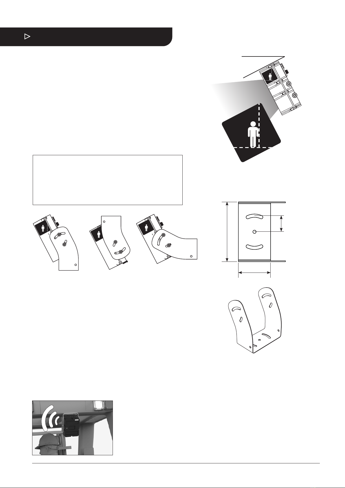
Sensor mounting
The supplied stainless steel mounting bracket can be used on
horizontal, vertical, or angled surfaces. The sensor should be
mounted approximately 2 metres / 6-7 feet above the ground.
1. Choose mounting option A, B, or C as shown below.
2. Noting the required bracket orientation relative to the
sensor, securely attach the bracket to a solid surface using
appropriate M6 fasteners and torque settings.
3. Mount the sensor in the bracket as shown in the diagram.
Finger-tighten the four M6 screws (supplied) to hold the
sensor in the bracket. Adjust the sensor to the correct angle
using the sticker as a guide. (Refer to page 10 if using a
Weather Shield.)
4. Tighten the four M6 mounting screws to a maximum of 10Nm.
Note. An additional custom mounting plate may be required to
mount the IRIS 860 bracket in the required location.
WARNING. Do not drill into any roll-over or falling-object
protection structure (ROPS / FOPS) as this may compromise
the strength of the structure and void the machine warranty.
A. On top B. Underneath* C. Vertical**
27º
Correct angle
The sticker indicates
the correct angle
*Not compatible with a Weather Shield. Refer to page 10.
**The vertical mount option may not be suitable for installations
where multiple sensors are used because the sensor bracket
cannot be rotated to the required angle. Refer to page 12.
Alert volume
The 94dB alert may be uncomfortably loud if the sensor is
mounted close to the operator’s head. Options:
• Consider a Top Mount instead of an Underneath Mount.
• Set the sensor to Reduced Volume in the IRIS 860 setup app.
• Use SEEN’s snap-on volume reduction cap accessory.
35mm
130mm
70mm

© Copyright 2021 Seen Safety Limited. IRIS 860 Installation Guide. Version 2.3 6
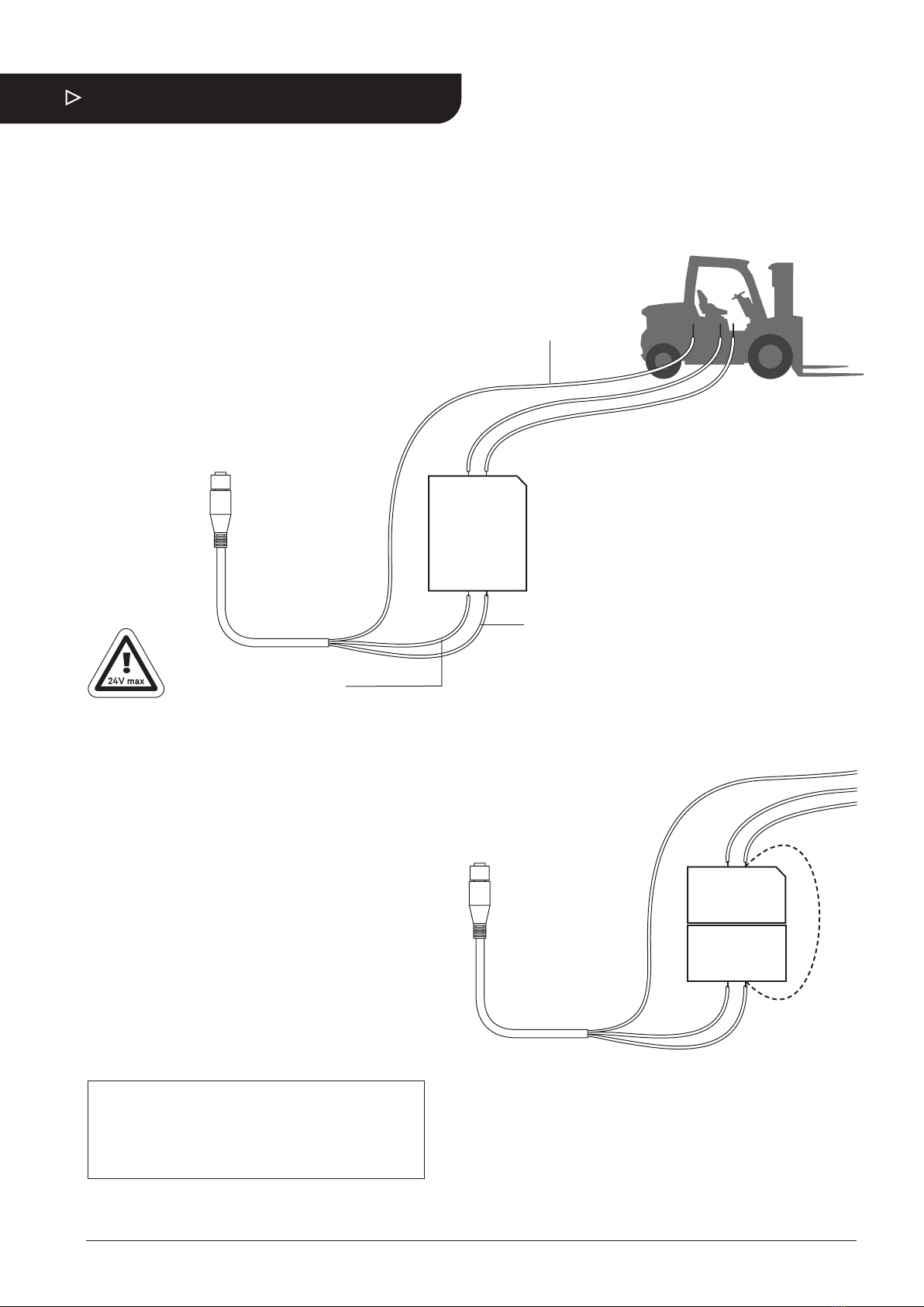
Sensor wiring
IRIS 860 sensors and Cab Boxes require a 12–24
volt power supply. Power supplies exceeding
24 volts require a DC/DC voltage converter.
• If using a Cab Box skip to page 7.
• Use a voltage reducer if the supply voltage is greater than
24 volts. Refer to page 4.
• The direction signal input can be up to 100V.
• Follow the machine manufacturer instructions for
connecting a third-party accessory.
IRIS 860 sensor
Ground
Direction (centre)
Ignition power
Orientation slot
Sensor Power Cable (5 pin)
IRIS 860 sensor
Accessory socket
Power socket
Sensor Power
Cable
BROWN
Power (ignition)
DC 12-24V 0.7A
BLUE
Ground
BLACK
Direction signal
DC 3.5-100V 1mA
Correct functionality
• Power on > Green LED and single beep followed by red LED
flash (to indicate the sensor has booted) then steady green
LED.
• Detection > Red LED and continuous audible alert.
• Pre-alert (if set) > Flashing Red LED and beeping audible
alert.
Direction Dependent Alert
By default IRIS 860 sensors are pre-set so they can only alert if
they are receiving a direction signal (usually reverse) from the
machine. This direction dependent setting can be changed in
the IRIS 860 setup app.

© Copyright 2021 Seen Safety Limited. IRIS 860 Installation Guide. Version 2.3 7
Cab Box
Sensor Cable
Cab Box
Power Cable
Cab Box
Cab Box wiring
A Cab Box is used on closed-cab machines to provide an audible
detection alert and LED indication to the operator inside the cab. Up
to four IRIS 860 sensors can be connected to each Cab Box.
A Cab Box Sensor Cable is used to connect each sensor to the Cab
Box. These cables are available in 5m, 10m, or 15m lengths.
IRIS 860 sensor
Cab Box Sensor Cable
Cab Box

© Copyright 2021 Seen Safety Limited. IRIS 860 Installation Guide. Version 2.3 8
Cab Box Power Cable
IRIS 860 sensors and Cab Boxes require a 12–24
volt power supply. Power supplies exceeding
24 volts require a DC/DC voltage converter.
Note. The 5-pin sensor power cable supplied with each
sensor is not required and should NOT be used.
• Use a voltage reducer if the supply voltage is greater than
24 volts. Refer to page 4.
• The direction signal input can be up to 100V.
• Follow the machine manufacturer instructions for
connecting a third-party accessory.
BROWN
Power (ignition)
DC 12-24V 4.0A
BLUE
Ground
BLACK
Direction signal
DC 3.5-100V 1.0mA
Direction
Ground Ignition power
Orientation slot
Cab Box Power Cable (4 pin)
Correct functionality
The LED and audible alert on the Cab Box mirrors the LED and
audible alert on the connected sensor.
• Power on > Green LED and single beep followed by red LED
flash (to indicate the sensor has booted) then steady green
LED.
• Detection > Red LED and continuous audible alert.
• Pre-alert (if set) > Flashing Red LED and beeping audible
alert.
Direction Dependent Alert
By default IRIS 860 sensors are pre-set so they can only alert
if they are receiving a direction signal (usually reverse) from
the machine via the Cab Box. This direction dependent setting
can be changed in the IRIS 860 setup app.
4 pin Cab Box Power socket

© Copyright 2021 Seen Safety Limited. IRIS 860 Installation Guide. Version 2.3 9
Cab Box Sensor Cable
Cab Box Sensor Cables are used to connect the sensor to the
Cab Box. They are available in 5, 10, and 15 metre lengths. One
end of the cable has a re-wireable plug which can be removed to
assist the threading of the cable through the machine chassis or
to shorten the cable. When re-attaching the plug check that the
wire colours match the diagram below. Use the screw-block as a
reference.
Note. The re-wireable plug should be connected to the Cab Box
to protect it from the elements. The moulded end should be
connected to the sensor.
5. Grey (Centre)
4. Black
Screw-block
3. Blue
2. White
1. Brown
Re-wireable plug Wire stripping guide
9mm
16mm
Grey wire (centre)
Other wires
8mm 9mm
Moulded end
(Attach to sensor)
Re-wireable plug
(Attach to Cab Box)
Cab Box Sensor Cable
1. Unscrew first
2. Unscrew second
Cable

© Copyright 2021 Seen Safety Limited. IRIS 860 Installation Guide. Version 2.3 10
Weather Shield
A Weather Shield (P/n SI-115) helps protect the sensor from
rain, heat and UV.
Note. It is not possible to attach a weather shield to a sensor
mounted in the ‘Underneath’ position.
Step 1
Before installing the weather shield,
gently tighten screw A on both sides
to hold the sensor in the bracket at
the correct angle.
Step 3
Insert screw B on both sides. Check
the alignment and evenly tighten the
four M6 mounting screws to maximum
10Nm.
Step 2
Place the weather shield over the
sensor and bracket so that the round
holes in the weather shield fit over
screw A on both sides.
Screw A
Screw B
Screw A

© Copyright 2021 Seen Safety Limited. IRIS 860 Installation Guide. Version 2.3 11
Set-up examples
Forklift
• 1 or 2 sensors on the top-rear of the machine
• 3m critical risk zone
• 1m pre-alert zone
• Sensor set so to only alert in reverse
Wheel-loader
• 1 or 2 sensors on the back of the machine
mounted above the radiator
• A cab box inside the cab with cables connected
back to each sensor
• 5m critical risk zone
• 1.5m pre-alert zone
• Sensor set to only alert in reverse
Critical risk zone = continuous audible alert
Pre-alert = beeping audible alert
A customised detection zone can help to minimise
non-critical detections
Note. The scenarios shown above are examples only. Your
specific requirements may dier.

© Copyright 2021 Seen Safety Limited. IRIS 860 Installation Guide. Version 2.3 12
Dual sensor side-by-side
When two sensors are mounted side-by-side the sensor brackets
should be spaced approximately 160mm / 6” apart and rotated
approximately 20º outwards. The combined field-of-view is
around 100-105º depending on the amount of overlap.
30-35º
30-35º
20º
~ 160mm / 6” apart
~ 1m / 3ft apart
20º
Dual sensor cross-over
Compared to the side-by-side mounting option, the cross-over
mounting option oers improved detection zone overlap close to
the machine, reduces the 0-0.8m no-detection zone, and increases
the overall field-of-view.
The sensor brackets should be spaced approximately 1m / 3ft
apart (about the width of a forklift cab / wheel loader engine) and
each bracket should be rotated approximately 30-35º inwards.
The combined field-of-view is around 120-130º depending on the
amount of overlap.
CHECK. In either option, when
angled correctly both sensors
should simultaneously detect a
person standing in the center of the
detection zone at the maximum and
minimum detection range.

© Copyright 2021 Seen Safety Limited. IRIS 860 Installation Guide. Version 2.3 13
Internal self check function
IRIS 860 sensors have an automatic internal self-checking
function. If a fault is detected the sensor (and cab box if
used) will flash and beep a pattern indicating the type of fault
detected.
Window contamination dust/dirt
Situation: The sensor operates in a dusty or dirty environment
Problem: The sensor windows are excessively contaminated.
Indication: Continuous beep and flash sequence long-short-
short, long-short-short etc. — - - — - - — - - — - -
Solution: Clean the sensor windows
Window contamination ice/condensation
Situation: The sensor operates in a cold store / freezer
environment.
Problem: Ice or condensation on the windows may be
triggering the window self check test.
Indication: Beep and flash sequence long-short-short, long-
short-short etc. (— - - — - - — - - — - - )
Possible solution: First check whether pedestrian workers can
be reliably detected with ice or condensation present on the
windows. If detection is reliable, then the window self check
function may be turned o using SEEN’s setup app. Use this
setting with caution because the window self-check function
will be disabled. Contact SEEN customer support for more
information.
Sensor internal fault
Any error sequence that is NOT long-short-short, long-short-
short indicates an internal fault. Unplug the sensor and contact
your reseller or supplier to arrange repair or replacement.
IRIS 860 sensors have no user-serviceable parts.
Sensor maintenance
IRIS 860 sensors have no user-serviceable parts.
Other than keeping the windows and buzzer free of dust and
dirt, no scheduled maintenance is required.
Remove dust and dirt using clean water and a clean non-
abrasive cloth.
Do not use high pressure water jets to clean.
Do not use chemical cleaners including alcohol, benzene,
thinners, and degreasers.

© Copyright 2021 Seen Safety Limited. IRIS 860 Installation Guide. Version 2.3 14
Trouble-shooting
1. The sensor LED is green on but the sensor does not
alert
Possible cause 1: The sensor may be set to only alert when
it receives a direction (usually reverse) signal input, but the
direction signal has not been connected.
Solution: Ensure the direction input is correctly wired to the
machine’s direction signal.
Possible cause 2: The retroreflective test target is too close
to the sensor.
Solution: Move further back. Detection starts 0.8m (3 ft)from
the sensor face.
2. A sensor set to be direction dependent, always alerts
Possible cause: The reverse signal input wire is twisted
together with the ignition power, meaning the sensor is always
receiving a direction signal input.
Solution: Ensure the power cable direction signal wire is
correctly wired to the machine’s direction signal.
3. The sensor and/or Cab Box are correctly wired but the
sensor/s do not behave in the expected way
Possible cause: Electrical earthing issue on the reverse signal.
Solution: Check that the ground reference on the direction
signal is the same as the ground reference on the sensor
power supply. Refer to page 16.
4. The Cab Box is correctly wired but the sensor/s do not
behave in the expected way
Possible cause: Wrong power cable.
Solution: Use the 4 PIN Cab Box power cable supplied
with the Cab Box. Do not use the 5 PIN sensor power cable
supplied with each sensor.
5. The sensor repeatedly beeps and flashes with the
sequence long-short-short, long-short-short
Cause: Blocked window.
Solution: Clean the windows and the self-check alert should
cease. If the sensor is operating in a cold-store freezer, ice on
the window maybe triggering the self checking function. Refer
to the Internal Self Check section on page 12.
6. The sensor is beeping and flashing and the sequence
is NOT long-short-short, long-short-short
Cause: Internal fault detected.
Solution: There are no user serviceable parts. Contact your
supplier for repair or replacement.

© Copyright 2021 Seen Safety Limited. IRIS 860 Installation Guide. Version 2.3 15
7. A sensor with a connected accessory will not power
up when plugged in with a USB config cable.
Cause: The USB port cannot supply suicient power.
Solution: Unplug the accessory from the sensor before
connecting the USB config cable.
8. At start-up the sensor gives a continuous tone alert
when the vehicle is in gear.
Cause: Test Mode may be enabled and has been
inadvertently activated. Refer to page 22.
9. Direction signal grounding issue
Applies to a sensor or Cab Box connected to a direction signal
input (e.g. reverse). If a DC/DC converter is used also refer to
page 4.
Note: In this example the direction signal is REVERSE.
Problem: The sensor / cab box is correctly powered and
connected to the reverse direction signal, but the sensor does
not alert, even when the reverse direction signal is active.
Possible cause: The reverse direction signal and sensor power
supply may not share a common ground.
To check the reverse direction signal ground:
• Unplug the sensor or Cab Box power cable
• Switch the vehicle ignition to ON (preferably without
starting the vehicle for safety)
• Attach a voltmeter across the ignition power pin (+) and
the ground pin (–) of the power cable. The voltage should
be between +10V and +29V. Refer to the plug diagrams
opposite.
• Next, attach the voltmeter across the reverse direction pin
and the ground pin (–). When the vehicle is NOT in reverse,
the voltage should measure between 0V and +1V. When the
vehicle IS in reverse it should measure between +3V and
+100V.
If the vehicle is in reverse and the voltage is not 3-100V
between the ground pin (–) and the reverse direction pin,
there may be a grounding issue.
Direction
Signal
Cab Box Power Cable
Ignition power (+)
Orientation slot
Ground (–)
Direction (centre)
Sensor Power Cable
Ignition power
Orientation slot
Ground

© Copyright 2021 Seen Safety Limited. IRIS 860 Installation Guide. Version 2.3 16
–
+
Connecting an accessory
The 8-pin M12 accessory socket outputs an electrical signal
while the IRIS 860 is detecting. The signal output behaviour
can be controlled in the IRIS 860 setup app. By default the
detection signal is only live during a detection in the Critical
Alert zone.
Accessory Cable
The IRIS 860 Accessory Cable (P/n SI-121) can be used to
connect a third-party accessory such as a camera, data-
logger, light etc.
IMPORTANT. Do not attach the Accessory Cable to a Cab
Box. The Accessory Cable is for the IRIS 860 sensor only.
Pin no. Wire colour Description
1 Brown 12V accessory power supply
2 White Ground / Earth
3 Blue Detection NPN
4 Black Detection 3.6V logic output
5Grey Do not connect
6 Pink Detection 12V logic output
Note. Refer to the accessory socket pin-out diagram on
page 23 for the complete specification.
Accessory use-case examples
External buzzer or light
On detection the NPN transistor switch closes putting 12V
across the connected accessory. The maximum supply current
is 500mA.
6
1
2
Alignment slot
3
4
5
12V power supply (BROWN)
IRIS 860 ground (WHITE)
Detection NPN (BLUE)
Detection 3V6 (BLACK)
Do not connect (GREY)
Detection 12V (PINK)
Accessory socket Accessory cable
Pin
1
2
3
4
5
6
7
8
NPN switch connects
to Ground during
detection
12V accessory
Ground

© Copyright 2021 Seen Safety Limited. IRIS 860 Installation Guide. Version 2.3 17
–
+
Camera with digital input
The IRIS 860 accessory power supply is used to power
the camera accessory (maximum supply current 500mA).
Detection 12V puts 12V on the camera trigger during detection.
This is a low power output and can only sink/source a few
milliamps of current. If required, add an external regulator to
limit the 12V detection logic output voltage (e.g. down to 5V or
3.3V) or use Detection 3V6 (black) for a 3.6V detection output.
External relay
On detection the NPN transistor switch closes putting 12V
across the relay. A flywheel diode is required across the relay
coil to protect the NPN transistor against the coil transient
when the detection event ends and the coil is switched o.
–
+
12V power supply (BROWN)
IRIS 860 ground (WHITE)
Detection NPN (BLUE)
Detection 3V6 (BLACK)
Do not connect (GREY)
Detection 12V (PINK)
12V power supply (BROWN)
IRIS 860 ground (WHITE)
Detection NPN (BLUE)
Detection 3V6 (BLACK)
Do not connect (GREY)
Detection 12V (PINK)
Accessory socket
Accessory socket
Accessory cable
Accessory cable
Pin
1
2
3
4
5
6
7
8
Pin
1
2
3
4
5
6
7
8
NPN switch connects
to Ground during
detection
Output high
during detection
Logic buer
12V relay
12V camera
Ground
Ground
Flywheel diode
12V power supply
12V trigger input

© Copyright 2021 Seen Safety Limited. IRIS 860 Installation Guide. Version 2.3 18
Changing the sensor settings
Requirements
• IRIS 860 sensor
• IRIS 860 USB Config Cable P/n SI-122
• SEEN’s free IRIS 860 setup app
• A Mac or Windows computer with a USB port, or an OTG
compatible Android smart phone or tablet
You may also need
• A USB OTG adapter*
• An IRIS 860 USB Config Cable to Sensor Cable Adapter
P/n SI-124
*AnOTGorOn The Goadapter(sometimes called anOTG
cable, orOTG connector) allows you to connect a full sized
USB-A cable to your phone or tablet through the Micro USB
or USB-C chargingport. These adapters are available from
technology retailers.
Device compatibility
• Not all smart phones and tablets are USB OTG compatible
• Non OTG compatible devices cannot support USB serial
communications and will not connect to the sensor
• Some OTG compatible smart phones and tablets will not
supply suicient power to the sensor
• Check your device can connect to an IRIS 860 sensor
BEFORE going on site.
Note. SEEN have tested and recommend the LENOVO Tab
M8 HD P/n TB-8505F tablet it to provide reliable connection.
(This tablet requires a USB OTG Micro USB adapter.)
Note. If the sensor has an accessory attached, remove the
accessory prior to attaching the USB config cable. The
accessory may draw more power than the USB plug can
supply and the sensor will not power on.
Software
Download IRIS 860 setup app at
www.seensafety.com/download

© Copyright 2021 Seen Safety Limited. IRIS 860 Installation Guide. Version 2.3 19
USB OTG
adapter
Cable Adapter
2
USB Config
Cable
USB Config
Cable
USB Config
Cable
USB connection
Direct to sensor
• Launch the SEEN IRIS 860 setup app
• Connect the IRIS 860 sensor to the computer or Android
mobile device using an IRIS 860 USB Config Cable (OTG
compatible smart phones or tablets will require a USB OTG
adapter)
• Wait a few seconds for the sensor to power up and boot
(indicated by red LED flash then steady green)
• The sensor LED will glow green when powered on
• Follow the on-screen instructions.
Cab Box
Power Cable
1
Cab Box
Sensor Cable
Cab Box
Sensor Cable
Via the Cab Box Sensor Cable
If direct access to the sensor is diicult the USB config cable
can be connected to a Cab Box Sensor Cable from inside the
cab.
• Requires an IRIS 860 Cable Adapter (P/n SI-124)
• Launch the SEEN IRIS 860 setup app
• Unplug the relevant Cab Box Sensor Cable from the Cab
Box and plug it into the Cable Adapter
• Attach the Cable Adapter to the USB Config Cable
• Plug the USB plug into the USB port on the computer or
Android mobile device. (For OTG compatible smart phone or
tablet a USB OTG adapter will be required)
• Wait a few seconds for the sensor to power up and boot
(indicated by red LED flash then steady green)
• Follow the on-screen instructions.

© Copyright 2021 Seen Safety Limited. IRIS 860 Installation Guide. Version 2.3 20
Software settings
Sensor settings can be changed using SEEN’s free IRIS 860
setup app.
Critical alert
A detection in the Critical alert zone is indicated by a
continuous audible alert tone from the sensor (and Cab Box if
used). The factory default setting is 4m / 12 ft.
Pre-alert
A detection in the Pre-alert zone is indicated by a beeping
audible alert tone. The factory default setting is 0m.
Note: The combined total of Critical alert distance plus Pre-
alert distance cannot exceed 8.0 metres.
Direction Dependent Alert
Requires connection to the vehicle direction signal (e.g.
forward or reverse). Options:
• Sensor can only alert when the direction signal is active
• Sensor can only alert when the direction signal is not active
• Sensor can always alert (direction signal is ignored)
Volume
Options: Normal / Reduced / OFF
When Reduced is selected the alert volume is decreased from
94dB at 1 metre to approximately 86dB at 1 metre. This setting
can be used in situations where the sensor is mounted close to
the operators head and the alert is uncomfortably loud.
OFF completely disables the audible alarm. Use with caution.
Test Mode
Options: ON / OFF
If Test Mode is set to ON in the sensor setup software, the
machine operator can toggle the sensor into a mode where
it temporarily ignores the Direction Dependent Alert setting.
This allows the operator to safely walk around the machine
to test the sensor is detecting without needing to put the
machine in a reverse or forward gear.
Procedure
Turn the ignition on (to power the sensor), wait 2 to 5 seconds,
then turn the ignition o. The next time the ignition is turned
on the sensor will be toggled to Test Mode, indicated by a
flashing green LED on the sensor (and Cab-Box if used).
Test Mode lasts 2 minutes. The green LED on the sensor (and
Cab Box if used) flashes to indicate Test Mode is active.
The operator can check the sensors are working by walking
into the detection zone wearing a reflective safety vest.
Detection is indicated by an audible alert tone and red LED.
Direction signal check
This test ensures the Direction Dependent Alert signal is
connected. While Test Mode is active, when the operator
engages the Direction Dependent Alert gear, the audible alert
should sound indicating that the direction signal is correctly
connected.
Other manuals for IRIS 860 Sensor
3
This manual suits for next models
2
Table of contents
Other Seen Accessories manuals


