SEFRAM MW9520 User manual

MW9520
CABLE LOCATOR
INSTRUCTION MANUAL

Index
1. Introduction..........................................
2. Safety notes.........................................
3. Features..............................................
4. Specications......................................
5. Instrument layout.................................
6. Operation.............................................
7. Maintenance........................................
Page
1
2
3-4
5-6
7-11
12-20
21-22

-1-
1. Introduction
Note
This cable locator has been designed and tested
according to CE Safety Requirements for Electronic
Measuring Apparatus, EN 61010-1 EN 61326-1 and
other safety standards. Follow all warnings to ensure
safe operation.
Warning
Read "Safety Notes"(next page) before using the cable
locator.
-2-
2. Safety Notes
●Read the following safety information carefully before
attempting to operate or service the cable locator.
● Use the cable locator only as specied in this manual,
otherwise the protection provided by the cable locator
may be impaired.
●Rated environmental conditions:
(1) Indoor use.
(2) Installation Category III 300V
(3) Pollution Degree 2.
(4) Altitude up to 2000 Meter.
(5) Relative Humidity 80% Max.
(6) Ambient Temperature 0~40℃.
●Observe the international electrical symbols listed
below.
Meter is protected throughout by double
insulation or reinforced insulation.
Warning ! Risk of electric shock.
Caution ! Refer to this manual before using the
meter.
Earth (ground).

-3-
3.Features
Transmitter
●The MW9520 transmitter is a great tool for locating
and identifying cables and individual conductors.
●Designed for locating unenergized cables and
powered cables.
●Voltage measurement for cables :
ACV 12V~300V
DCV 12V~300V
●Signal Transmission
• Transmission Power Level Selection
(includes 1, 2, 3)
• Transmission Signal Code Selection
(includes F, E, H, d, L, C, O, A)
●Flashlight & Back Light function.
●The Silent Mode (Disable Button Beep).
●The Level Bar Display on the LCD Screen
(the transmission power level indication).
●The Action Wave Display on the LCD Screen
(when the signal is transmitted).
●Auto power off function.

-4-
Receiver
●The MW9520 receiver is designed to identify and
trace wires or cables.
●Designed for locating unenergized cables and
powered cables.
●Signal Detection (includes Level, Code, Value)
• Automatic Mode
• Manual Mode (There are 9 levels to select).
●UAC Mode (AC Power Line Detection)
●Flashlight & Back Light function.
●The Silent Mode (Disable Button Beep & Frequency
Tone)
●The Danger Symbol is to indicate the AC voltage on
the Line.
●The Level Bar Display on the LCD Screen for the
signal value & the UAC power value.
●Auto power off function.

-5-
4. Specications
Transmitter
Output signal frequency 125kHz
Voltage measurement range
Accuracy
12~300V AC / DC
±(2%rdg+2dgt)
Display LCD shows function and
bargraph
Power source 1.5V (AAA) battery × 6
Fuse 690V/0.5A (6.3 × 32mm)
Operating temperature
& humidity
0°C~40°C
80% R.H. Max.
Storage temperature
& humidity
-10°C~50°C
80% R.H. Max.
Dimensions 247(L)×78(W)×45(D)mm
Weight(battery included) Approx. 389g
Receiver
Detection depth < 50cm
Display LCD shows function and
bargraph
Power source 1.5V (AAA) battery × 6
Operating temperature
& humidity
0°C~40°C
80% R.H. Max.
Storage temperature
& humidity
-10°C~50°C
80% R.H. Max.
Dimensions 188(L)×90(W)×47(D)mm
Weight(battery included) Approx. 324g
-6-
●Safety Standard :
EN 61010-1 CAT III 300V
EN 61326-1
●Low battery indication:
" " symbol appears and ashes on the LCD
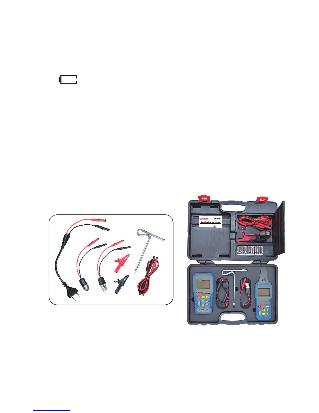
●Accessories :
Instruction manual
Test leads
Alligator clip
Spike
Batteries
Carry case
-7-
5. Instrument layout
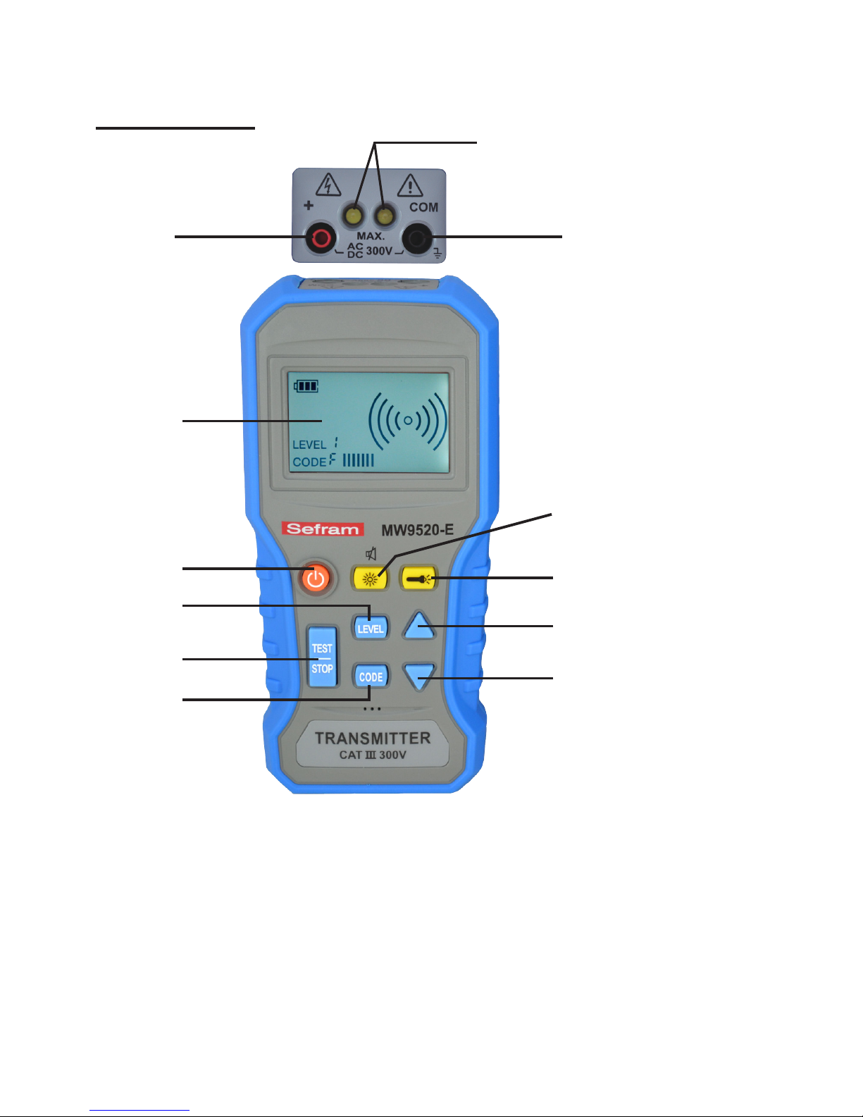
Transmitter
⑴ "+" Terminal ⑺ Flashlight Button
⑵ "COM" Terminal ⑻ TEST/STOP Button
⑶ Flashlight ⑼ LEVEL Button
⑷ LCD ⑽ CODE Button
⑸ ON/OFF Button ⑾ Button
⑹ Backlight and Mute Button ⑿ Button
⑷
⑸
⑻⑿
⑾
⑺
⑹
⑼
⑽
⑴ ⑵
⑶

-8-
(1) "+" Terminal
This is the positive terminal. Use the RED test
lead to connect.
(2) "COM" Terminal
This is the ground terminal. Use the Black test
lead to connect.
(3) Flashlight
(4) LCD
(5) ON/OFF Button
Press the ON/OFF button to turn on or turn off the
transmitter.
(6) Backlight and Mute Button
Press it to turn on or turn off the LCD Backlight.
Press and hold it for more than 1 second to switch
on or switch off the mute function.
(7) Flashlight Button
Press it to turn on or turn off the LED lights.
(8) TEST/STOP Button
Press it to send a transmission signal or stop
sending the transmission signal.
(9) LEVEL Button
Press it to enter into the level selection mode, the
"LEVEL" symbol will be flashing on the LCD.
There are 3 levels to select.
(10) CODE Button
Press and hold it for more than 1 second to enter
into the code selection mode, the "CODE" symbol
will be ashing on the LCD. There are 8 codes to
select: F, E, H, d, L, C, O, A.

-9-
(11) Button
Press it to select the level upwards when the
transmitter is in the level selection mode.
Press it to select the code upwards when the
transmitter is in the code selection mode.
(12) Button
Press it to select the level downwards when the
transmitter is in the level selection mode.
Press it to select the code downwards when the
transmitter is in the code selection mode.
-10-
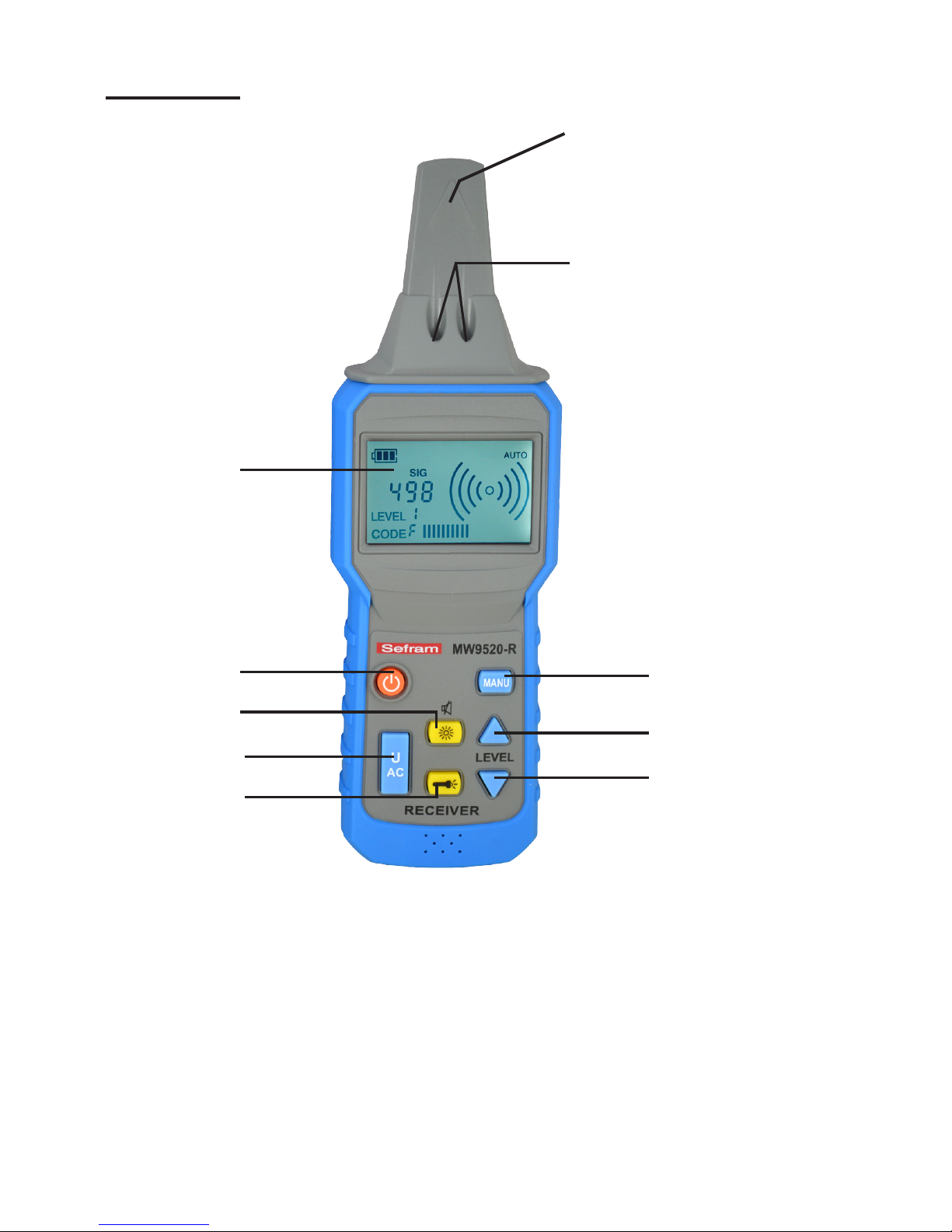
Receiver
⑴ Sensor of the Receiver ⑹Backlight and Mute Button
⑵ Flashlight ⑺UAC Button
⑶ LCD ⑻Flashlight Button
⑷ ON/OFF Button ⑼ Button
⑸ MANU Button ⑽ Button
⑴
⑷⑸
⑻
⑺
⑹⑼
⑽
⑵
⑶

-11-
(1) Sensor of the Receiver
Sensor of the receiver is used to detect the
transmission signal.
(2) Flashlight
(3) LCD
(4) ON/OFF Button
Press the ON/OFF button to turn on or turn off the
transmitter.
(5) MANU Button
Press it to enter into the manual detection mode,
there are 8 sensitivity levels to select.
(6) Backlight and Mute Button
Press it to turn on or turn off the LCD Backlight.
Press and hold it for more than 1 second to switch
on or switch off the mute function.
(7) UAC Button
Press it to switch to the non-contact voltage
detection mode(UAC mode).
(8) Flashlight Button
Press it to turn on or turn off the LED lights.
(9) Button
Press it to select the sensitivity level upwards
when the receiver is in the manual detection
mode.
(10) Button
Press it to select the sensitivity level downwards
when the receiver is in the manual detection
mode.

-12-
6. Operation
The transmitter has 3 different modes:
●Test mode:
When the power is on, the transmitter is on the test
mode. It can measure the AC or DC voltage of cable.
When the user presses the TEST/STOP button, the
transmitter will send a high frequency transmission
signal down the cable. When the user presses the
TEST/ STOP button again, the transmitter will stop
sending the transmission signal.
●Level selection mode:
Press the LEVEL button to enter into the level
selection mode of the transmitter, the LEVEL symbol
will be ashing. User can press or button to
select the level of the transmission signal (level: 1~3).
The transmitter will return to the test mode by pressing
the LEVEL button again.
●Code selection mode:
Press and hold the CODE button for more than 1
second to enter into the code selection mode of the
transmitter, the CODE symbol will be ashing. User
can press or button to select the code of the
transmission signal (code: F, E, H, d, L, C, O, A).
Once the code selection is done, the transmitter will
return to the test mode by pressing the CODE button
again.

-13-
The receiver has 3 different modes:
●Auto detection mode:
When the power is on, the receiver is on the auto
detection mode to detect the high frequency
transmission signal with the highest sensitivity.
The speaker in the receiver will generate a
tone(550Hz ~ 1.6kHz) and the bar-graph on the LCD
indicates the signal strength.
●Manual detection mode:
Press the MANU button to enter into the manual
detection mode. On the manual detection mode, user
can select the signal sensitivity level (8 steps) by
pressing or button. The receiver will return to the
auto detection mode by pressing the MANU button.
●UAC detection mode:
Press the UAC button to enter into the non-contact
voltage detection mode (UAC mode) for non-contact
voltage detection. The is for checking the AC power
lines or the wall outlets.

-14-
Cable Locating:
(1) Single-pole application:
(a) Connect the "+" (red) terminal to a single
conductor, and connect the "COM" (black)
terminal to earth. If there are other conductors in
the same piping, then they have to be earthed
at the same time. In this case, the MW9520-R
can detect the NG position.

-15-
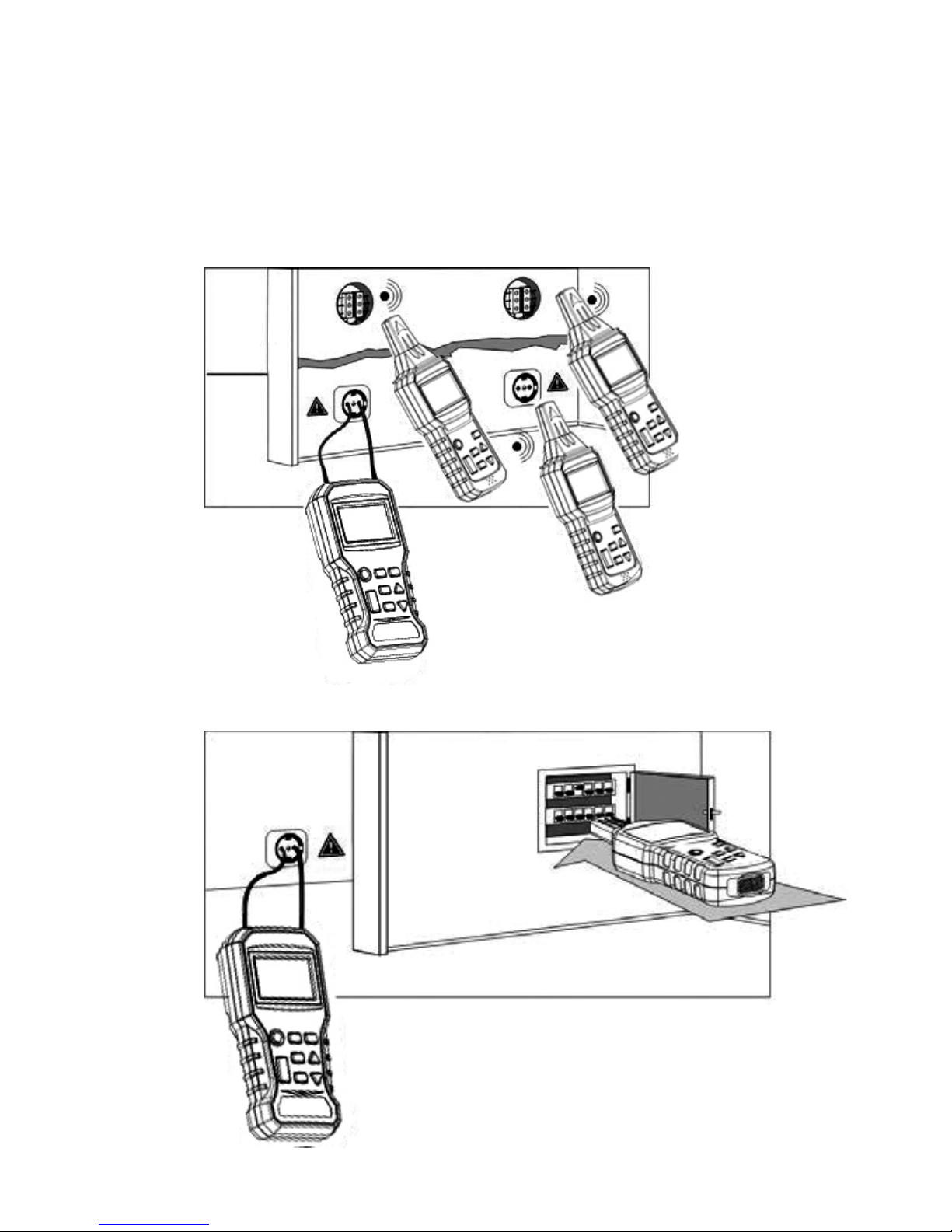
(b) Locating and tracing lines and outlets:
The circuit must not be live when it is detected,
connect the "+" (red) terminal of MW9520-E to
the phase and the other "COM" (black) terminal
to the protection earth wire. If the cable supplied
by the signals from the transmitter is near other
conductors that are parallel to it (example:
cable tray, channel, etc.) or is interlaced with or
crosses them, the signal may then propagate in
these cables and create spurious circuits then
be detected.
(2) Two-pole application:
(a) The live line connection:
Connect the "+" (red) terminal of MW9520-E to
the phase line of the mains, and connect the
"COM" (black) terminal to the neutral line of the
mains. In this case, the MW9520-E can
-16-
measure the voltage of mains line and transmit
the signal through the mains line, then the
MW9520-R can trace the mains line and detect
the power socket is locating on the same mains
line or not.

-17-
(b) The dead line connection:
Connect the both terminals of MW9520-E to
the two ends of wires in the line, and connect
the wires together on the other end of line. In
another method, connect the both terminals
of MW9520-E to the two ends of a single line.
In this case, the MW9520-R can nd out NG
position or trace the signal line in the wall or
oor.

-18-
(3) Other application:
(a) Detection of a metallic water supply and heating
pipe:
The pipe must be conductive, and so metallic.
(for example galvanized steel)
The pipe must not be earthed, and there is a
relatively high resistance between itself and
ground. (otherwise, the detection distance is
very short)
Connect "+" (red) terminal of MW9520-E to the
pipe and "COM" (black) terminal of MW9520-E
must be earthed.
Table of contents
Other SEFRAM Test Equipment manuals


Popular Test Equipment manuals by other brands


Seaward
Seaward PrimeTest 300 operating instructions

PCE Health and Fitness
PCE Health and Fitness PCE-RT 2200 user manual

AEMC
AEMC GROUNDFLEX 6474 user manual

GW Instek
GW Instek GDS-800 Series Operation manual

pico Technology
pico Technology TA062 user guide

Good Will Instrument
Good Will Instrument GSB-01 quick start guide


