Good Will Instrument GSB-01 User manual

Multiplex Scanner Box
GSB-01/GSB-02
QUICK START GUIDE
GW INSTEK PART NO. 82SB-02000M01
ISO-9001 CERTIFIED MANUFACTURER
Test Equipment Depot - 800.517.8431 - 99 Washington Street Melrose, MA 02176
TestEquipmentDepot.com

This manual contains proprietary information, which is protected by
copyright. All rights are reserved. No part of this manual may be
photocopied, reproduced or translated to another language without
prior written consent of Good Will company.
The information in this manual was correct at the time of printing.
However, Good Will continues to improve products and reserves the
right to change specification, equipment, and maintenance
procedures at any time without notice.
Good Will Instrument Co., Ltd.
No. 7-1, Jhongsing Rd., Tucheng Dist., New Taipei City 236, Taiwan.

Table of Contents
3
Table of Contents
SAFETY INSTRUCTIONS ................................................... 4
Safety Symbols............................................................................................. 4
Safety Guidelines ......................................................................................... 5
Power cord for the United Kingdom ........................................................... 8
INTRODUCTION............................................................... 9
Series lineup ................................................................................................ 9
Firmware Note............................................................................................. 9
Model Overview......................................................................................... 10
Main Features............................................................................................ 10
Accessories and Package Contents........................................................... 11
Panel Overview .......................................................................................... 12
Appearance ................................................................................................ 12
GSB-01 Front Panel ................................................................................... 12
GSB-02 Front Panel ................................................................................... 12
GSB-01 Rear Panel..................................................................................... 13
GSB-02 Rear Panel..................................................................................... 13
Test Lead Connection................................................................................ 14
Connecting GSB-01 Units ......................................................................... 14
Connecting GSB-02 Units ......................................................................... 17
OPERATION .................................................................... 20
Menu Tree.................................................................................................. 20
Common Utility Settings........................................................................... 21
Scan Configuration.................................................................................... 23

GSB-01/GSB-02 Quick Start Guide
4
SAFETY INSTRUCTIONS
This chapter contains important safety
instructions that you must follow during
operation and storage. Read the following before
any operation to ensure your safety and to keep
the instrument in the best possible condition.
Safety Symbols
These safety symbols may appear in this manual or on the
instrument.
WARNING
Warning: Identifies conditions or practices that
could result in injury or loss of life.
CAUTION
Caution: Identifies conditions or practices that
could result in damage to the instrument or to
other properties.
DANGER High Voltage
Attention Refer to the Manual
Protective Conductor Terminal
Frame or Chassis Terminal
Earth (ground) Terminal
Test Equipment Depot - 800.517.8431 - 99 Washington Street Melrose, MA 02176
TestEquipmentDepot.com

SAFETY INSTRUCTIONS
5
Do not dispose electronic equipment as unsorted
municipal waste. Please use a separate collection
facility or contact the supplier from which this
instrument was purchased.
Safety Guidelines
General
Guideline
CAUTION
Do not place any heavy object on the
instrument.
Avoid severe impact or rough handling that
leads to damaging the instrument.
Do not discharge static electricity to the
instrument.
Use only mating connectors, not bare wires, for
the terminals.
Do not block the cooling fan opening.
Do not disassemble the GSB-01/GSB-02 unless
you are qualified.
(Measurement categories) EN 61010-1:2010 specifies the
measurement categories and their requirements as follows. The
GSB-01/GSB-02 falls under category II.
Measurement category IV is for measurement performed at the
source of low-voltage installation.
Measurement category III is for measurement performed in the
building installation.
Measurement category II is for measurement performed on the
circuits directly connected to the low voltage installation.
Power Supply
WARNING
AC Input voltage range: 100 - 240VAC ±10%
Frequency: 50Hz/60Hz
To avoid electrical shock connect the protective
grounding conductor of the AC power cord to
an earth ground.

GSB-01/GSB-02 Quick Start Guide
6
Fuse
WARNING
Fuse Type: T 2A/250V
To ensure fire protection, replace the fuse only
with them specified type and rating.
Disconnect the power cord before replacing the
fuse.
Make sure the cause of the fuse blowout is fixed
before replacing the fuse.
Cleaning the
GSB-01/GSB-02
Disconnect the power cord before cleaning.
Use a soft cloth dampened in a solution of mild
detergent and water. Do not spray any liquid.
Do not use chemicals containing harsh material
such as benzene, toluene, xylene, and acetone.
Operation
Environment
Location: Indoor, no direct sunlight, dust free,
almost non-conductive pollution (Note below)
Relative Humidity: ≤ 70% (no condensation)
Altitude: < 2000m
Temperature: 0˚C~40˚C
(Pollution Degree) EN 61010-1:2010 specifies the pollution degrees
and their requirements as follows. The GSB-01/GSB-02 falls under
degree 2.
Pollution refers to “addition of foreign matter, solid, liquid, or
gaseous (ionized gases), that may produce a reduction of dielectric
strength or surface resistivity”.
Pollution degree 1: No pollution or only dry, non-conductive
pollution occurs. The pollution has no influence.
Pollution degree 2: Normally only non-conductive pollution
occurs. Occasionally, however, a temporary conductivity caused
by condensation must be expected.
Pollution degree 3: Conductive pollution occurs, or dry, non-
conductive pollution occurs which becomes conductive due to
condensation which is expected. In such conditions, equipment
is normally protected against exposure to direct sunlight,
precipitation, and full wind pressure, but neither temperature
nor humidity is controlled.

SAFETY INSTRUCTIONS
7
Storage
environment
Location: Indoor
Temperature: -10°C to 70°C
Relative Humidity: ≤ 85% (no condensation)
Disposal
Do not dispose this instrument as unsorted
municipal waste. Please use a separate collection
facility or contact the supplier from which this
instrument was purchased. Please make sure
discarded electrical waste is properly recycled to
reduce environmental impact.
Test Equipment Depot - 800.517.8431 - 99 Washington Street Melrose, MA 02176
TestEquipmentDepot.com

GSB-01/GSB-02 Quick Start Guide
8
Power cord for the United Kingdom
When using the scanner box in the United Kingdom, make sure the
power cord meets the following safety instructions.
NOTE: This lead/appliance must only be wired by competent persons
WARNING: THIS APPLIANCE MUST BE EARTHED
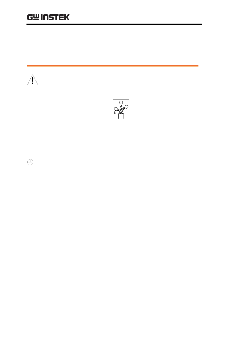
IMPORTANT: The wires in this lead are coloured in accordance with the
following code:
Green/ Yellow:
Earth
Blue:
Neutral
Brown:
Live (Phase)
As the colours of the wires in main leads may not correspond with
the coloured marking identified in your plug/appliance, proceed
as follows:
The wire which is coloured Green & Yellow must be connected to
the Earth terminal marked with either the letter E, the earth symbol
or coloured Green/Green & Yellow.
The wire which is coloured Blue must be connected to the terminal
which is marked with the letter N or coloured Blue or Black.
The wire which is coloured Brown must be connected to the
terminal marked with the letter L or P or coloured Brown or Red.
If in doubt, consult the instructions provided with the equipment
or contact the supplier.
This cable/appliance should be protected by a suitably rated and
approved HBC mains fuse: refer to the rating information on the
equipment and/or user instructions for details. As a guide, a cable
of 0.75mm2should be protected by a 3A or 5A fuse. Larger
conductors would normally require 13A types, depending on the
connection method used.
Any exposed wiring from a cable, plug or connection that is
engaged in a live socket is extremely hazardous. If a cable or plug is
deemed hazardous, turn off the mains power and remove the cable,
any fuses and fuse assemblies. All hazardous wiring must be
immediately destroyed and replaced in accordance to the above
standard.

INTRODUCTION
9
INTRODUCTION
This Quick Start Guide is intended as a fast introduction to
operating the GSB-01/02 scanner boxes with the GPT-9000 safety
testers. This Quick Start Guide assumes that the user is familiar
with the GPT-9000 series safety testers.
For comprehensive instructions, please see the User Manual,
located on the accompanying CD.
Series lineup
The aim of these scanner boxes is to allow multiple DUTs to be
tested either concurrently or in sequence using the GPT-9800, GPT-
9900 or GPT-9900A safety testers. The scanner boxes are
particularly well suited for multi-point safety testing as well for
volume testing on factory floors.
The GSB-01 has connections for ACW, DCW and IR testing, while
the GSB-02 also includes support for GB testing.
Firmware Note
Please make sure the firmware is up to date before using the
scanner boxes. Please see the user manual to check the firmware
version.
GPT-9800: firmware version V3.0 or above
GPT-9900/9900A: firmware version V2.0 or above
Note: Throughout this guide, the terms scanner box or GSB will
refer to either model (GSB-01, GSB-02) unless specifically stated
otherwise. GPT-9000 will refer to any of the GPT-9800, GPT-9900 or
GPT-9900A safety testers, unless stated otherwise. HV and H will
refer to High Voltage terminals, while LO and L will refer to the
return terminal.

GSB-01/GSB-02 Quick Start Guide
10
Model Overview
Model name
ACW
DCW
IR
GB
Outputs
GSB-01
8 x HV
GSB-02
6 x HV, 2 x GB
Main Features
Performance
8 HV outputs (6 for GSB-02)
2 GB outputs (GSB-02 only)
ACW: 5kV AC
DCW: 6kV DC
IR: 1kV DC
GB: 40A (GSB-02 only)
Features
PASS/FAIL LEDs
HI LO LEDs
Up to 4 scanner boxes can be connected
Interface
RS-232 interface
Test Equipment Depot - 800.517.8431 - 99 Washington Street Melrose, MA 02176
TestEquipmentDepot.com

INTRODUCTION
11
Accessories and Package Contents
Standard
Accessories
Part number
Description
N/A
GSB-01/02 unit
N/A
Quick start guide
N/A
User manual CD
Region dependent
Power cord
GHT-108 x1
High voltage wiring leads
GHT-109 x1
GB wiring leads (GSB-02 only)
GHT-116R
x8(GSB-01), x6(GSB-02)
HV test leads for scanner box
outputs
GHT-116B x1
Return test lead for scanner
box
GTL-116R x2
GB sense/source H test lead
(GSB-02 only)
GTL-116B x1
GB sense/source L test lead
(GSB-02 only)
GTL-235
RS232C Cable
Note
Keep the packaging, including the box, polystyrene
foam and plastic envelopes should the need arise
to return the unit to GW Instek.

GSB-01/GSB-02 Quick Start Guide
12
Panel Overview
Appearance
GSB-01 Front Panel
Mul pl x Sc nner B x
GSB-01
CAUTION
H I
LO
H I
LO
H I
LO
H I
LO
H I
LO
H I
LO
H I
LO
H I
LO
CHANNEL
POWER
1234567
PASS
FA L
HIGH VOLTAGE
5 kVAC M X.
6 0 kVDC M X.
RETURN
HI / LO Indicators
HIGH VOLTAGE
Indicator
POWER Button
Channel Pass/Fail Indicators
Return Terminal
GSB-02 Front Panel
SOURCE H SOURCE L
SENSE H SENSE L
RETURN
H -POT
R
GSB-02 Mul pl x Sc nner B x
GB Rx
POWER
H I
1CHANNEL PASS
FA
LO
2
LO
3
H I
4
LO
5
LO
6
H I
7
H I
8
HIGH VOLTAGE
CAUTION 0 kVAC M X.
6 0 kVDC M X.
LO LO LO LO
H I H IH I H I
HI / LO Indicators
HIGH VOLTAGE
Indicator
POWER Button
Channel Pass/Fail Indicators
Return
Terminal/
SENSE L
SOURCE L
SOURCE HSENSE H

INTRODUCTION
13
GSB-01 Rear Panel
HV1 HV2
RETURN
CH1
CH2
CH3
CH4 CH6
CH5 CH7
CH8
GND
ENS RE THE P WER S RE E FR
THE NS R ENT BEF RE REP N THE F SE
24
5 6 Hz 5 X
2 25
RS232 IN
RS232 OUT
SER. NO. LB
OUTPUT
H H T E
X
6
5
NPUT
H H T E
X
6
5
HV1 HV2 CH1
Return
CH3 CH5
CH2 CH4
CH7
RS232/
IN
RS232/
OUT
CH6 CH8 GND
Line voltage input & fuse
GSB-02 Rear Panel
HV1 HV2 OUTPUT
H T
X
6
5
CH3
CH4 CH6
CH5
CH7
GND
ENS RE THE P WER S RE E R
THE N TR ENT BEF RE REP N THE F SE
24
5 6 Hz 5 X
2 5
RS23 N
RS232 OUT
CH8
CH1
CH2
GB Rx
SENSE H
SOURCE H
SENSE L
SOURCE L
H -POT
R
RETURN
SER. NO. B
NPUT
H T
X
6
5
HV1 HV2 CH1
Return/ SENSE L
CH3 CH5
CH2 CH4
CH7
RS232/
IN
RS232/
OUT
CH6 CH8 GND
Line voltage input & fuse
SOURCE H SOURCE L
SENSE H
Test Equipment Depot - 800.517.8431 - 99 Washington Street Melrose, MA 02176
TestEquipmentDepot.com

GSB-01/GSB-02 Quick Start Guide
14
Test Lead Connection
This section describes how to connect the GPT-9000 to a number of
scanner boxes. It is recommended that only models of the same
type are connected together.
Connecting GSB-01 Units
WARNING
Ensure the safety tester is off when connecting the
scanner boxes to the safety tester.
When wiring the GSB-01scanner boxes to the
safety tester or to each other, only the HV wiring
leads (GHT-108) should be used.
Front Panel
1. Connect the High Voltage terminal on the
safety tester to the High voltage terminal on the
1st scanner box, as shown below.
2. Connect the return terminal on the safety tester
to the return terminal on the 1st scanner box.
3. Connect the return terminal on the 2nd scanner
box to the return terminal on the 3rd scanner
box.

INTRODUCTION
15
POWER
START S OP
REMOTE
MANU AU E AVE U Y
A
PA S FA L EADY TE T
GPT 9803 Tes er
H GH VOL AGE
CAUT ON 50 VA M X
6 0 V M X
A D W h nd g o a e
n u a n Re n e
RE URN
u
GSB 01
T N
H H
HA E
WER
5 6 8
S
H V A
V
V
u
GSB 01
T N
H H
HA E
WER
5 6 8
S
H H V A
V
V
u
GSB 01
T N
H H
HA E
WER
S
H V A
V
V
HV cable
Return cable
Safety Tester
Scanner box #1
Scanner box #2
Scanner box #3
u
GSB 01
T N
H H
H
WER
S
H H V A
V
V
Scanner box #4
Rear Panel
1. Connect the rear panel HV terminals together
on the scanners.
HV2 (box #1) HV1 (box #2)
HV2 (box #2) HV1 (box #3)
HV2 (box #3) HV1 (box #4)
2. Connect the Return terminals together on
scanners*.
Return (box #1) Return (box #2)
Return (box #3) Return (box #4)
*Box #2 does not need to be connected to box
#3 as it was already connected from the front
panel.

GSB-01/GSB-02 Quick Start Guide
16
3. Connect the RS232 ports from the safety tester
to each scanner box in a daisy chain using the
RS232C cables.
RS232 (safety tester) RS232/IN (box #1)
RS232/OUT (box#1) RS232/IN (box #2)
RS232/OUT (box#2) RS232/IN (box #3)
RS232/OUT (box#3) RS232/IN (box #4)
HV V H H H H
HS R H O OV D O
H NS RU N B R P C G H S
H
S
S B
GH O
M
H VO
M
HV V H H H H
HS R H O OV D O
H NS RU N B R P C G H S
H M
S B
GH O
M
H VO
M
S V B S S
V V S S V
S
N O G
ON
R G
HU
W
V
S S
S B
S R H O R S R V D
H NS U N B OR R P H US
B
RS232 RS232/IN
HV2 HV1
Return Return
RS232/OUT
RS232/IN
Safety Tester
Scanner box #1
HV V H H H H
HS R H O OV D O
H NS RU N B R P C G H S
H
S
S B
GH O
M
H VO
M
RS232/OUT
RS232/IN
Scanner box #2
Scanner box #3
HV V H H H H
HS R H O R R OV D O
H NS RU N B R R P C G H S
H
S
S B
GH O
M
H VO
M
HV2 HV1
Return Return
Scanner box #4
RS232/OUT
RS232/IN
Test Equipment Depot - 800.517.8431 - 99 Washington Street Melrose, MA 02176
TestEquipmentDepot.com

INTRODUCTION
17
Connecting GSB-02 Units
Background
The following will describe how to connect
scanner boxes to a GPT-9000 series safety tester
with ground bond test support. Up to 4 scanner
boxes can be connected. In the examples below
only 3 scanner boxes are connected.
When wiring the GSB-02 scanner boxes to the
safety tester or to each other, only the GB
wiring leads (GHT-109) should be used.
Front Panel
1. Connect the SOURCE H and SOURCE L
terminals on the safety tester to the same
terminals on the 1st scanner box.
2. Connect the SENSE H and SENSE L terminals
on the safety tester to the same terminals on the
1st scanner box.

GSB-01/GSB-02 Quick Start Guide
18
P WER
A
S V
C P G
GPT-9804 es e
H H V A
T N V
V
Rx
S
S
S S
S
C DC V
R G B
ASS A A Y S
S S
S S S S
GSB-02 u
B Rx
WER
HSS
H H
8
H H V A
T N V
V
S S
S S S S
GSB-02 u
B Rx
WER
HA E SS
2 3
456
H H
8
H H V A
T N V
V
S S
S S S S
GSB-02
B Rx
WER
HA E SS
2 3
456
H
A
N V
V
SOURCE L
Safety Tester
Scanner box #1
Scanner box #1
Scanner box #1
SOURCE H
SENSE L
SENSE H
Rear Panel
1. Connect the SOURCE H and SOURCE L
terminals on the 1st scanner box in series to the
same terminals on the 2nd and 3rd scanner box.
2. Connect the SENSE H and SENSE L terminals
on the 1st scanner box in series to the same
terminals on the 2nd and 3rd scanner box.
3. Connect the RS232 ports from the safety tester
to each scanner box in a daisy chain using the
RS-232C cables.
RS232 (safety tester) RS232/IN (box #1)
RS232/OUT (box#1) RS232/IN (box #2)
RS232/OUT (box#2) RS232/IN (box #3)

INTRODUCTION
19
HV HV2
H VO G
M
H H
H
S R H O R OV D RO
NS U N B R P C NG H US
H
S
H
H
H2
B Rx
SS
S B
GH O
M
H VO G
M
H H
H
S R H O R OV D RO
NS U N B R P C NG H US
H
S
H
B Rx
SS
S B
GH O
M
H VO G
M
H H
H
S R H O R S R OV D RO
NS U N B OR R P C NG H US
H M
S
H
B Rx
S S
S
S S
S
S B
GH O
M
S V B S S
V V S S V
S
N O G
ON
R G
HU
W
V
S
S B
NS R H PO R S R OV D
H NS U N B R R P C S
B
RS232 RS232/IN
RS232/OUT
RS232/IN
RS232/OUT
RS232/IN
Safety Tester
Scanner box #1
Scanner box #2
Scanner box #3
SOURCE L
SOURCE H
SENSE L
SENSE H
SOURCE L
SOURCE H
SENSE L
SENSE H
Test Equipment Depot - 800.517.8431 - 99 Washington Street Melrose, MA 02176
TestEquipmentDepot.com

GSB-01/GSB-02 Quick Start Guide
20
OPERATION
Menu Tree
status
SET
T
PASS/FA L result
status
OTS
P
status
YAER
D
status
EIV
W
status
IDE
T
Press
START
Press
STOP
Press
MANU/
AUTO
Scan for
connected
scanner boxes
Press
STOP
Press
STOP
Press
EDIT/
SAVE
Press
STOP2
PAGE View
(AUTO mode
only)1
Press
UTILITY
Press
ESC
Switch to AUTO
mode
MANU UTILITY
menu (MANU
mode only)1
Press
UTILITY
1 Press EDIT/SAVE to save settings, or ESC to cancel and return to the previous screen.
2 Press the STOP key twice for a FAIL result.
3 When in MANU mode, selecting MANU number 000 will enter the special manual mode.
4 The Sweep mode function is only accessible in the special manual mode.
Common Utility
Settings1
Switch to MANU
mode
Special manual
mode
Press
PAGE
Hold
MANU/
AUTO
MANU
no.
# 0003
SCAN Configuration
(MANU mode only)1
Press
ESC
Save the SCAN
configuration
Press
EDIT/
SAVE
PAGE View
(AUTO mode
only)1
Press
PAGE
CA NS
Press
Press
ESC
Press
PAGE
This manual suits for next models
1
Table of contents
Other Good Will Instrument Test Equipment manuals

Good Will Instrument
Good Will Instrument GOS-310 User manual

Good Will Instrument
Good Will Instrument GDS-806 Owner's manual

Good Will Instrument
Good Will Instrument GDS-3000A Series User manual

Good Will Instrument
Good Will Instrument PEL-2000B Series User manual

Good Will Instrument
Good Will Instrument Instek GRS-6052 User manual

Good Will Instrument
Good Will Instrument instek GOS-6200 User manual

Good Will Instrument
Good Will Instrument GOS-6051 User manual

Good Will Instrument
Good Will Instrument instek GOS-6200 User manual