36
www.seuservice.com
POWER SUPPLY, AND EARTH CONNECTION
● Be sure to independently use the power supply socket outlet equipped with
an Earth Leakage Breaker. Using a power supply without an Earth Leakage
Breaker can cause a re when electric leakage occurs.
● This product is designed for an electrical outlet with an earth element. The
power cord incorporates an earth wire. Improper grounding could result in
electrical shock to customers, damage to components, and/or malfunctioning.
● If an electrical outlet with an earth element is not available and a commercially
distributed conversion adapter is used, make sure that the product's earth termi-
nal is connected to a grounded terminal using an earth wire. Improper ground-
ing could result in electrical shock to customers, damage to components,
and/or malfunctioning.
● In order to ground securely, do not use the service outlet to supply the power
of the other satellites. Improper grounding could result in electrical shock to
customers, damage to components, and/or malfunctioning. (For TAIWAN)
● The electric current capacity of the service outlet for the satellites is 10A max.
Never use the service outlet for the machinery exceeding 10A. Using the
machinery exceeding 10A can cause generation of heat and re hazard. (For
TAIWAN)
● Ensure that the power cord and earth wire are not exposed on the surface (pas-
sage, etc.). If exposed, they can be caught and are susceptible to damage. If
damaged, the cord and wire can cause electric shock and short circuit acci-
dents. Ensure that the wiring position is not in the customer's passage way or
the wiring has protective covering.
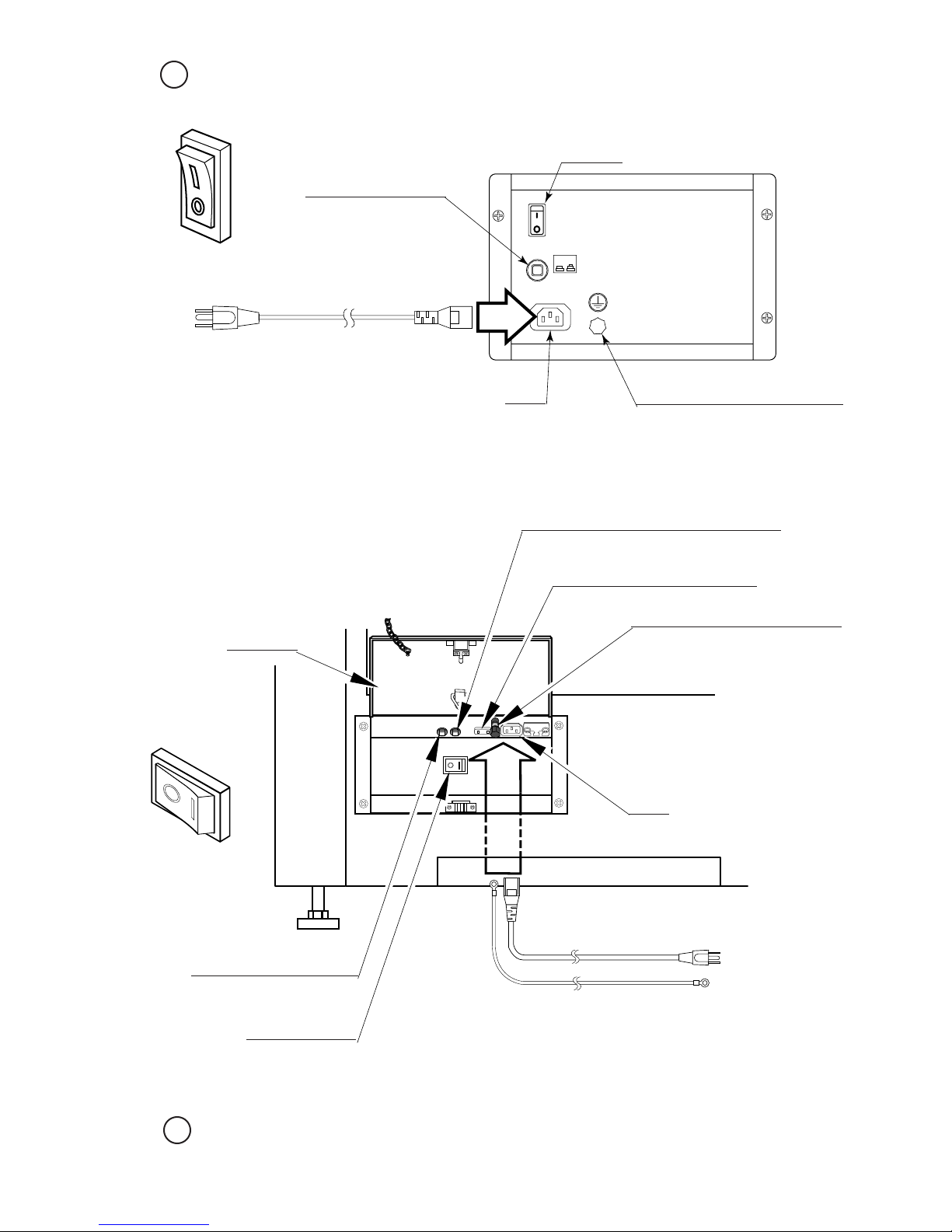
The AC unit for the main projection unit is located at the back of the cabinet. The AC unit features a
main switch, a circuit protector, an earth terminal, and an inlet for connecting the power cord.
FIG. 6. 3 a
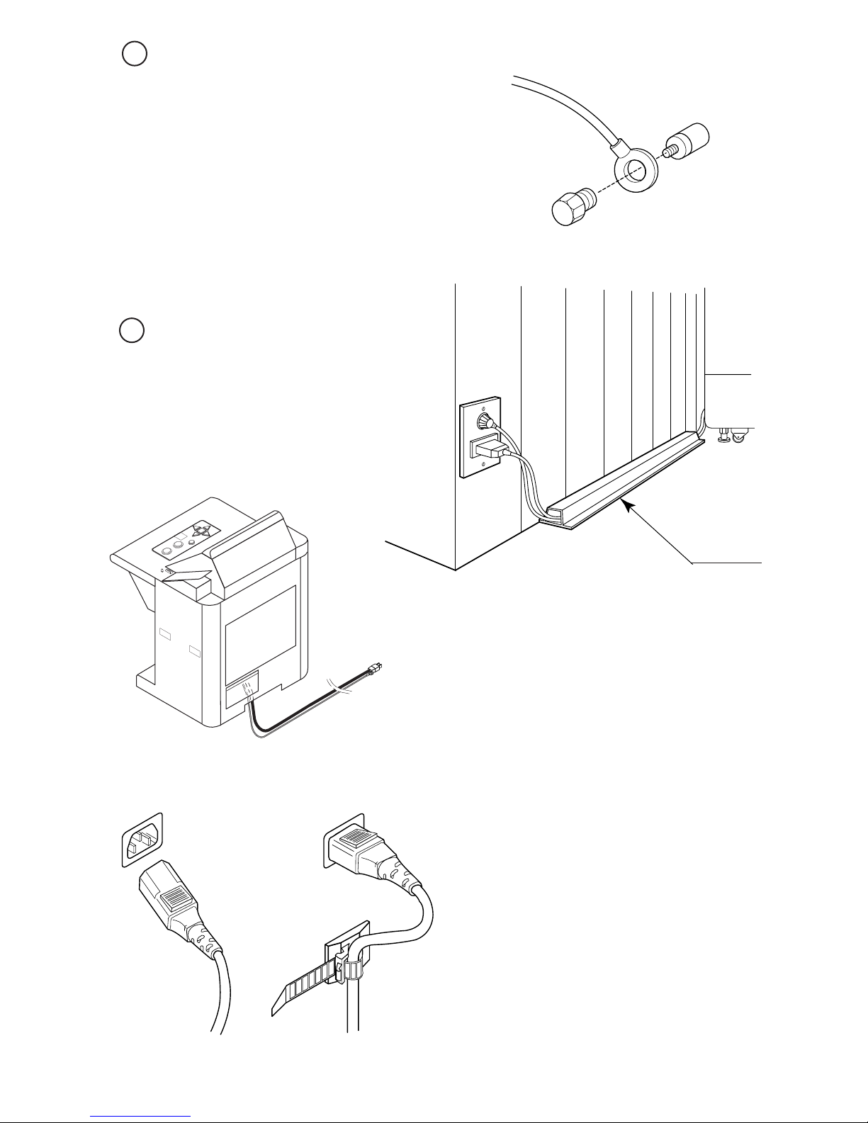
HOOK
LATCH AC COVER
When connecting the satellite
power source and earth, place the
latch located at the end of the chain
extending from the AC cover onto
the hook located on the back of the
satellite. This will secure the AC
cover in the open position. When
the work is nished, replace the
latch onto the hook located on the
back of the AC cover and close the
cover.
The AC unit for each satellite is also located at the
back. These AC units feature a power switch, a circuit
protector, an earth terminal, an inlet for connecting the
power cord, and a service outlet.
WARNING!
3