Sega Universal Kit User manual

1ST PRINTING JUNE 01
MANUAL NO. 999-1292
SEGA ENTERPRISES, INC. USA
Universal Kit
Kit Installation Instructions
& Service anual
Switchable FROM High Resolution 31K
TO Standard (Low) Resolution 15.75K.
1 - 2 PLAYER GAME
Warranty
Your new Sega Product is covered for a period of 90 days from the date of shipment. This certifies
that the Printed Circuit Boards, Power Supplies and Monitor are to be free of defects in workman-
ship or materials under normal operating conditions. This also certifies that all Interactive Control
Assemblies are to be free from defects in workmanship and materials under normal operating condi-
tions. No other product in this machine is hereby covered.
Sellers sole liability in the event a warranted part described above fails shall be, at its option, to
replace or repair the defective part during the warranty period. For Warranty claims, contact your
Sega Distributor.
Should the Seller determine, by inspection that the product was caused by Accident, Misuse, Ne-
glect, Alteration, Improper Repair, Installation or Testing, the warranty offered will be null and void.
Under no circumstances is the Seller responsible for any loss of profits, loss of use, or other dam-
ages.
This shall be the exclusive written Warranty of the original purchaser expressed in lieu of all other
warranties expressed or implied. Under no circumstance shall it extend beyond the period of time
listed above.

1
World Series 2001
Sega Naomi System
Kit Contains List
Part #
400-5397-01
3 -13616
560-5407-UL
3 -136 3-93CV1
600-7141-200
600-7009-2500
40-0051D-01
600-7247-500
LOC. PURCHASE
XKT-0 33
610-0630-0010
999-1293
999-1294
999-1295
999-1296
999-1297
NOA-20010-01
Desc
NAOMI POWER SUPPLY
AUDIO POWER AMP 2 CH
AUDIO XFORMER 120V
JAMMA I/O BD (NAOMI)
USB CABLE
VGA VIDEO CABLE
ASSY CASE PC1 DIMM BD
CABLE SCSI TYPE 2 500MM
SERVICE SWT BRKT ASSY
GD-ROM DRIVE KIT
GD SOFT KIT WS2K1
MARQUEE WS2K1
INST SHT AMER LG WS2K1
INST SHT NAT LG WS2K1
INST SHT CONTROL WS2K1
SIDE DECALS WS2K1
CONT PNL ASSY WS2K1
(See Breakdown Next Page.)
Qty
1
1
1
1
1
1
1
1
1
1
1
1
1
1
1
2
1
2
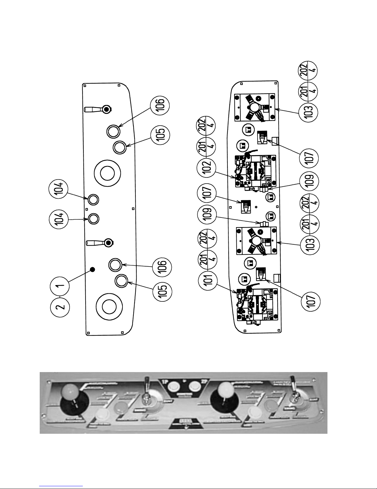
ASSY CTRL PNL 2A4B2S MB2K2 ENG (NOA-20010-01) (D-1/2)

3
ASSY CTRL PNL 2A4B2S MB2K2 ENG (NOA-20010-01) (D-2/2)
ITEM NO. PART NO. DESCRIPTION
1 HOT-2023 CTRL PNL BASE 2A4B2S
2 NOA-2025-01 CTRL PNL PLATE 2A4B2S ENG
101 610-6723-4B02 ASSY ANALOG JOY 4B PINK
102 610-6723-4B01 ASSY ANALOG JOY 4B GREEN
103 610-0409 ASSY BAT MECHA
104 999-1290 PUSHBUTTON RND YELLOW W/MICRO (2 PER)
105 999-10 6 PUSHBUTTON RND GREEN W/MICRO (2 PER)
106 999-12 9 PUSHBUTTON RND PINK W/MICRO (2 PER)
107 2 0-5009-01 CORD CLAMP 21
109 2 0-5275-SR10 CORD CLAMP SR10
201 050-U00400 U NUT M4
202 060-F00400 FLT WSHR M4
203 060-S00400 SPR WSHR M4
204 050-H00400 HEX NUT M4
4
SERVICE BULLETIN
SEGA Service Department http://www.seuservice.com
45133 Industrial Drive Phone: 415.701.6580
Fremont, Ca. 94538 Fax: 415.701.6594
If you have any questions please contact the SEGA Service Department at the numbers given above.
120
Feb 9. 2000
The SEGA Naomi Game kits are actually ‘JAMMA Dependent’. What this means exactly is they will only
install into existing JAMMA Cabinets. If an operator tries to install these kits into a Non-JAMMA cabinet,
they will first have to bring the wiring up to JAMMA Standards.
°Step 1 Disconnect the games original DC Power Supply. You may only use the power supply provided
with your kit. Be sure to set the voltages going to your Game BD to 5.1 and 3.3 volts DC to assure proper
operation ( Measure on Square Connector at Game BD. Yellow = 5vdc / Brown = 3.3vdc / White = Gnd )
°Step 2 You MUST USE THE COIN METER SUPPLIED WITH YOUR KIT to assure proper Coin
acceptance. A minimum 1 Gauge wire should be used from the Coin Meter 1 output line on your
JAMMA Harness. The 5vdc ( Yellow ) wire found in the wiring bag of your kit MUST BE USED for the
supply voltage to the meter.
SPECIAL NOTICE FOR
ALL SEGA NAOMI KITS
PROBLEM:
SOLUTION:
Not following the directions provided herein may cause your game to malfunction.
All electrical work should be performed by the site’s Serviceman or Technician.
In order to prevent an electric shock and short circuit, be sure to turn power off before performing
work or touching the interior parts of the product.
Be careful so as not to damage wirings. Damaged wiring can cause an electric shock or short circuit
accident.
Do not touch places other than those specified. Touching places not specified can cause an electric
shock or short circuit accident.
5
INSTALLATION INSTRUCTIONS
1) First. Remove all access panels from the game. Locate the original game Logic PCB’s & Power
Supply and remove from the Cabinet by first disconnecting all harnesses from the boards. (You need
only to splice in the Main Power (110v AC) into the 3-Pin Connector (GRN/WHT/BLK).)
2) Remove all existing game harnesses (we suggest using New Jamma Harnesses (NOT contained in the
kit) to ensure reliability).
3) Locate the most convenient and open area of the cabinet to mount the World Series 2001 Naomi
System Assembly. Make sure this area is free and clear of all cable harnesses and grounds, cable
clamps, etc.
Vacuum out or clean bottom of cabinet of dirt & miscellaneous parts (e.g.
screws, loose coins / tokens, etc.).
Remove all exterior decals and repair any cabinet damage. Repaint
cabinet if necessary. Remove the Monitor Plexi or if your game plexi has
Silk-screened artwork, you will need to strip it off.
4) Connect the JAMMA Harnesses to the JVS-JAMMA Interface Boards. Separate the wires from each
other (i.e. Control Panel, Video, Speaker, Power Supply). Run the various harnesses to the part of the
cabinet they go to ensuring they are dressed properly & secured to the cabinet. Locate the Volume/
Speaker/Coin Meter Cable and connect to your existing Switch Bracket or use the new one included
with the kit. Note: If you are using a VGA Compatible Monitor you can run your VGA Cable directly
to the monitor or connect it to your JV JAMMA Interface for RGB Conversion to your JAMMA
Cables.
5) Remove Marquee from cabinet and cut to fit the new World Series 2001 Marquee in place.
REPLACE old Joysticks & Buttons with the NEW ones supplied in Kit.
6) First remove all Joystick and Button assemblies from the Control Panel. Remove Lexan and Control
Panel Overlay. Proceed to clean surface of the Control Panel by removing all adhesive and dirt. Fill
in or plug up existing button holes to set up a blank work area for your new controls.
7) Install the new Control Panel Overlay by carefully peeling off the paper backing and laying down on
the panel. Smooth it out, starting in the center and working your way to the edges (removing all of
the trapped air pockets). If necessary, cut the edges of the overlay excess and fold under panel.
) Cut out the button and Joystick Holes. Install Joystick and buttons from kit into the Control Panel
and tighten down. Connect all game harness wires to switches and buttons.

6
INSTALLATION INSTRUCTIONS
9) Proceed to place new decals on the sides of the cabinet. Locate a new monitor bezel, if needed, and
replace glass, if required (due scratches). Install Instruction Placard to the back of the Monitor Glass.
NOTE: As a precaution, disconnect the JAMMA Harness from the I/O Boards and turn power on. With a
Multi-Meter, measure the 5v and 3.3v. Adjust if necessary to 5.15v DCand 3.3vDC. Measure the +12 to
ensure the wires and voltages are in the correct position. Turn power off. Plug in the JAMMA Harness once
again to the I/O Boards. The Attract Mode should appear on the screen.
Adjust the SIZE, CONTRAST, BRIGHTNESS, and COLORS on the
Monitor for optimum appearance. Adjust ERTICAL/HORIZONTAL
Hold to get a stable picture, if required.
Enter DIAGNOSTICS and adjust the Volume Level, test all Buttons &
Joystick for proper operation & wiring. Adjust Pricing. Coin-Up and
test out a game to ensure proper play functions are as they should be.

7
Sega Naomi System Switch
Bracket and Speaker
Installation Diagrams
(Figure 3)
Coin Meter
Test Service
Volume JAMMA Pin R
JAMMA Pin 15
JAMMA Pin 1
Yellow Wire from Extra
arness (+5v)
JAMMA Pin 8
+
_
Pin 1
Pin 5
Pin 4
To CN1 of
Amplifier Board
YEL/RED
W T/RED
GRN/RED
From CN2 of
Amplifier Board
From CN4 of
Amplifier Board
GRY/RED
ORG/RED
ORG/BLUE
GRY/BLUE
Left
Speaker
Right
Speaker
8
4
1
2
3
5
6
7
8
10
11
12
13
14
15
16
17
18
19
20
21
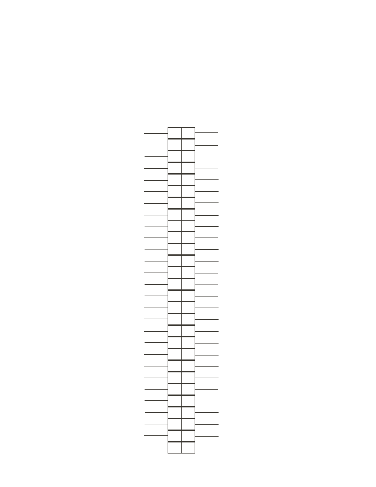
A
B
C
D
E
F
J
K
L
M
N
P
R
S
T
U
V
X
Y
Z
a
22
23
24
4
e
d
26
25 c
b
28 f
27
9
W
Ground
Ground
Ground
Ground
+5v (Not Used) +5v (Not Used)
+5v (Not Used) +5v (Not Used)
(Not Used) (Not Used)
+12v (Not Used) +12v (Not Used)
Key Key
Coin Meter 1 Coin Meter 2
(Not Used)
(Not Used)
(Not Used)
(Not Used)
(Not Used)
(Not Used)
Video Red
Video Blue
Video Ground
Video Green
Video Sync
Service
Test (Not Used)
Coin 1 Coin 2
1P Start 2P Start
1P UP 2P UP
2P Down
1P Down
1P Left 2P Left
1P Right
Attack 1P (1P SW1)
Grapple 1P (1P SW2)
Support 1P (1P SW3)
Ground
Ground
2P Right
Attack 2P (2P SW1)
Ground
Ground
Support 2P (2P SW3)
Grapple 2P (2P SW2)
(Not Used)
(Not Used)
(Not Used)
(Not Used)
Sega Naomi System
JAMMAHarness Wiring
(JAMMA I/O BD)
(Figure 4)
Table of contents
Other Sega Game manuals

Sega
Sega SONIC PLUS User manual

Sega
Sega IG02401E User manual

Sega
Sega EMERGENCY CALL AMBULANCE User manual

Sega
Sega Let's Go ISLAND! User manual

Sega
Sega TETRIS GIANT User manual

Sega
Sega Crazy Taxi User manual

Sega
Sega Jumbo!Safari User manual

Sega
Sega Jambo!Safari User manual

Sega
Sega 999-1108 User manual

Sega
Sega WaveRunner User manual


Popular Game manuals by other brands


Fundex Games
Fundex Games Timber Tumble User instructions

Go! Gater
Go! Gater 1-1-16453-TP02 Assembly instructions

Smoby
Smoby BBF Challenger quick start guide

Hathaway
Hathaway BG2019SK Assembly instructions

Roberto Sport
Roberto Sport INGLESE Assembly instructions

Beleduc
Beleduc XXL Witches' Kitchen Instruction


