Segway RMP User manual
Segway®Robotic Mobility Platform
User Guide
Segway Inc.
14 Technology Drive
Bedford, NH 03110
Segway is a registered trademark of Segway Inc.
®

Version 2.0 Segway RMP – User Guide
20277-00001 aa 2
Contents
Contents...................................................................................................................................... 2
How to use this guide ................................................................................................................ 3
Introduction ................................................................................................................................ 6
Segway Robotic Mobility Platform Models.............................................................................. 7
Balancing RMP Models ............................................................................................................7
Statically Stable RMP Models .................................................................................................. 8
Operator Supplied Equipment .................................................................................................. 9
RMP Specifications ................................................................................................................ 10
Assembly .................................................................................................................................. 12
RMP100 and RMP200............................................................................................................ 12
RMP50.................................................................................................................................... 14
RMP400.................................................................................................................................. 15
Theory of Operation: Balancing Dynamics ........................................................................... 16
Interaction With The Environment .......................................................................................... 16
Fore/Aft Motion ....................................................................................................................... 19
Turning ................................................................................................................................... 23
Configuration and Operation .................................................................................................. 24
Emergency-stop (E-stop) Function......................................................................................... 24
Safety Shutdown Function ..................................................................................................... 25
Basic Operation ...................................................................................................................... 26
Error Conditions...................................................................................................................... 30
Tire Pressure .......................................................................................................................... 31
RMP Configuration Parameters ............................................................................................. 32
Battery Packs ........................................................................................................................... 35
Safety Guidelines ................................................................................................................... 36
Charging ................................................................................................................................. 38
General Battery Information ................................................................................................... 41
Service Operations .................................................................................................................. 43
Contact and legal information ................................................................................................ 45
Report All Incidents ................................................................................................................ 45
How to Reach Us.................................................................................................................... 45
California Warning .................................................................................................................. 45
Segway Inc Patent and Licensing Information ....................................................................... 45
Glossary.................................................................................................................................... 46

Version 2.0 Segway RMP – User Guide
20277-00001 aa 3
How to use this guide
This guide is provided with Segway Robotic Mobility Platforms (RMP) to aid
users in understanding and integrating the Segway RMP into their application.
• Read this entire guide before turning on the RMP. Users of the RMP100
and RMP200 should pay particular attention to “Theory of Operation:
Balancing Dynamics”.
• Study and understand the section describing the Emergency Stop (E-stop)
and Safety Shutdown functions.
• Browse the “Segway Robotic Mobility Platform Interface Guide” to
understand the control and command architecture of the RMP.
• Install the appropriate USB Driver software before connecting the RMP to
a PC via USB.

Version 2.0 Segway RMP – User Guide
20277-00001 aa 4
The Segway RMP is a powerful machine – its motors can
produce over 2 hp under certain transient conditions. Read and
fully understand the material in this guide before attempting to
use the RMP.
Do not sit, stand, or ride on the RMP
Do not drive the RMP at people or animals
Only enable the balance controller when the
platform is free to tilt [-20,20] degrees.
Do not lift the RMP off the ground when it is
balancing – the control system will spin the wheels
in an attempt to stay balanced.
20° 20°
!WARNING
Risk of Death or Serious Injury
Version 2.0 Segway RMP – User Guide
20277-00001 aa 5
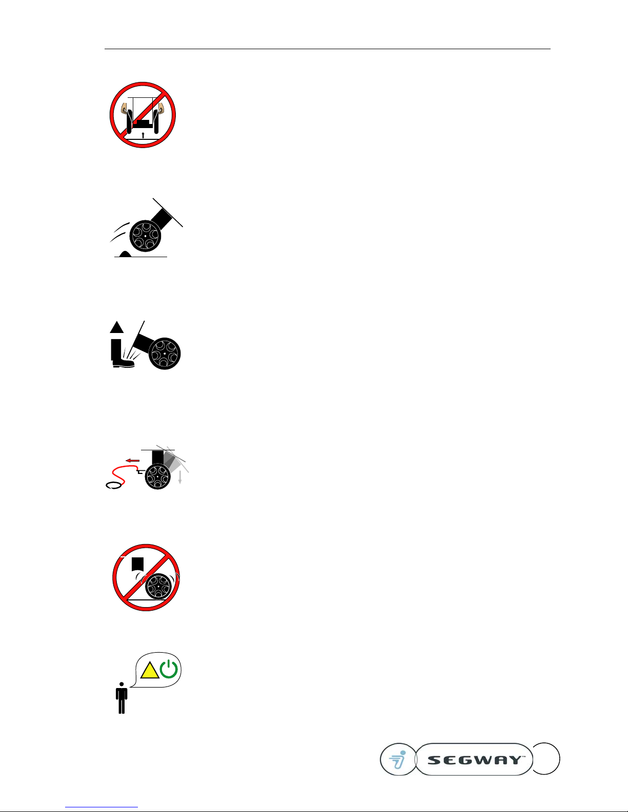
Do not lift the RMP by the wheels – your hands
may get pinched if the frame rotates
Avoid slippery surfaces, loose materials, or any
other surface that does not provide good traction.
Avoid obstacles and any terrain feature that could
interfere with wheel movement.
Disabling the balance controller will cause the
RMP to fall over – A falling RMP could strike
persons or objects nearby.
Pulling the E-Stop Lanyard will cause the RMP to
fall over – A falling RMP could strike persons or
objects nearby.
Do not enter balance mode without the frame
attached.
Alert people in the vicinity when RMP operation is
commencing.
!
!

Version 2.0 Segway RMP – User Guide
20277-00001 aa 6
Introduction
Segway Inc. provides these instructions for users of the Segway™ Robotic Mobility Platform
(RMP). These instructions and the Segway RMP are designed for use by research scientists and
engineers who are experienced with tele-operated and autonomous robots and their safe use.
Persons who lack that experience should not attempt to use the Segway RMP.
The Segway RMP is based on the design of the Segway Human Transporter (HT). The RMP is a
transportation platform designed for integration into a system that has a “control processor.” The
control, or host processor must create velocity and steering commands and output these in the
correct message format to the RMP. The control processor may communicate with the RMP
using either CAN bus or USB. The document “Segway Robotic Mobility Platform Interface Guide”
is essential to understanding communication between the control processor and the RMP. The
control processor may be a laptop receiving joystick commands from a stationary PC, a small
microcontroller (e.g. a Microchip PIC processor), or some other device that can send velocity and
steering commands to the RMP via USB or CAN bus.
The system designer is responsible for implementing appropriate safety
systems to prevent damage and/or injury. The system designer must
understand the operation of the RMP and anticipate hazards that may
result from loss of control or interaction with the environment. The Segway
RMP provides both a control command and an emergency stop switch that
can stop its forward movement in an emergency.
Use of the Segway RMP involves risk. If an RMP tire loses traction or runs into an obstacle, the
Segway RMP can fall over. If the RMP experiences an internal malfunction, the RMP may fall
over. If possible, the Segway RMP will perform a “Safety Shutdown” and automatically come to a
stop in the event of fully discharged battery packs or certain failures in the balancing system.
(After 10 seconds of audible warning, the RMP will shutdown - if the RMP is in “Balance Mode”, it
will fall over.) The Segway RMP does not dynamically balance laterally, so cornering at too great
a speed or traversing a slope can cause the Segway RMP to tip over sideways. The Segway
RMP is equipped with an E-stop tether. Pulling the tether will disable all motor power. In each of
these cases, the Segway RMP could cause injury to nearby person(s) or damage to property
situated on or near the Segway RMP. Careful use of the Segway RMP reduces, but does not
eliminate this risk. This risk may be further reduced by using the Segway RMP in “Tractor Mode”
and attaching additional ground contacting supports (e.g. casters) as described in the Tractor
Mode section of these instructions.
The Segway RMP should not be used to transport any person. Persons should not sit, stand, or
in any way attempt to ride on the Segway RMP.
Read and understand these instructions thoroughly before attempting to use the Segway RMP.
Retain this document for future reference.
Version 2.0 Segway RMP – User Guide
20277-00001 aa 7
Segway Robotic Mobility Platform Models
This guide is intended to help you setup and properly use the Segway RMP. There are five RMP
models, three balancing models (RMP100, RMP200 and RMP200ATV) and two non-balancing
models (RMP50 and RMP400).
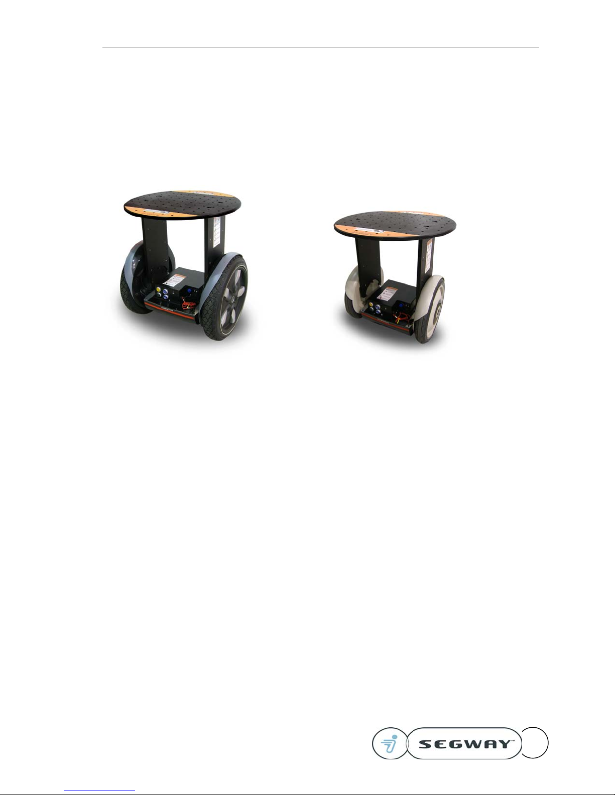
Balancing RMP Models
RMP 200 RMP 100
RMP 100: based on the p series Segway Human Transporter (HT).
RMP 200: based on the i Series Segway HT.
RMP 200ATV: based on the Offroad Series Segway XT.
Operation of these three models is nearly identical except for payload and terrain capabilities.
The RMP 100 has been tuned to handle lighter payloads and is more suitable for flat surfaces.
The RMP 200 has larger wheels and stronger motors to handle more challenging terrain and
larger payloads. The RMP200ATV is configured lithium batteries and all-terrain tires to enable
the highest level of terrain and payload capability.
Balancing RMP models have two operating modes: “Tractor Mode” and “Balance Mode”.
Tractor Mode provides statically stable operation, with a larger footprint and lower payload
height. The limits of stability are defined by the distribution of the contact points and the height of
the center of gravity.
Balance Mode provides dynamically stable operation with a smaller footprint and higher payload
height. This has the benefit of allowing for a much higher center of gravity while still maintaining
a small footprint.
Version 2.0 Segway RMP – User Guide
20277-00001 aa 8
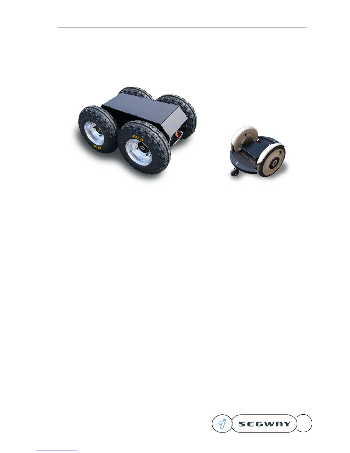
Statically Stable RMP Models
RMP 400 RMP 50
RMP 400: based on the Segway XT.
RMP 50: based on the p series Segway HT.
The RMP400 and RMP50 have only one operating mode: “Tractor Mode”
Tractor Mode provides statically stable operation, with a larger footprint and lower payload
height. The limits of stability are defined by the distribution of the contact points and the height of
the center of gravity.

Version 2.0 Segway RMP – User Guide
20277-00001 aa 9
Operator Supplied Equipment
The velocity and turn rate of the RMP are controlled via USB or Controller Area Network (CAN)
bus commands. These may be generated using a dedicated microcontroller, a PC system or
other computer based system to initiate commands. The user must provide a computer system
and write an application to communicate with the RMP.
The “Segway Robotic Mobility Platform Interface Guide” provides detailed information about the
communications interface. The information contained in the interface guide will be necessary to
control the RMP with a device other than the demonstration system.

Version 2.0 Segway RMP – User Guide
20277-00001 aa 10
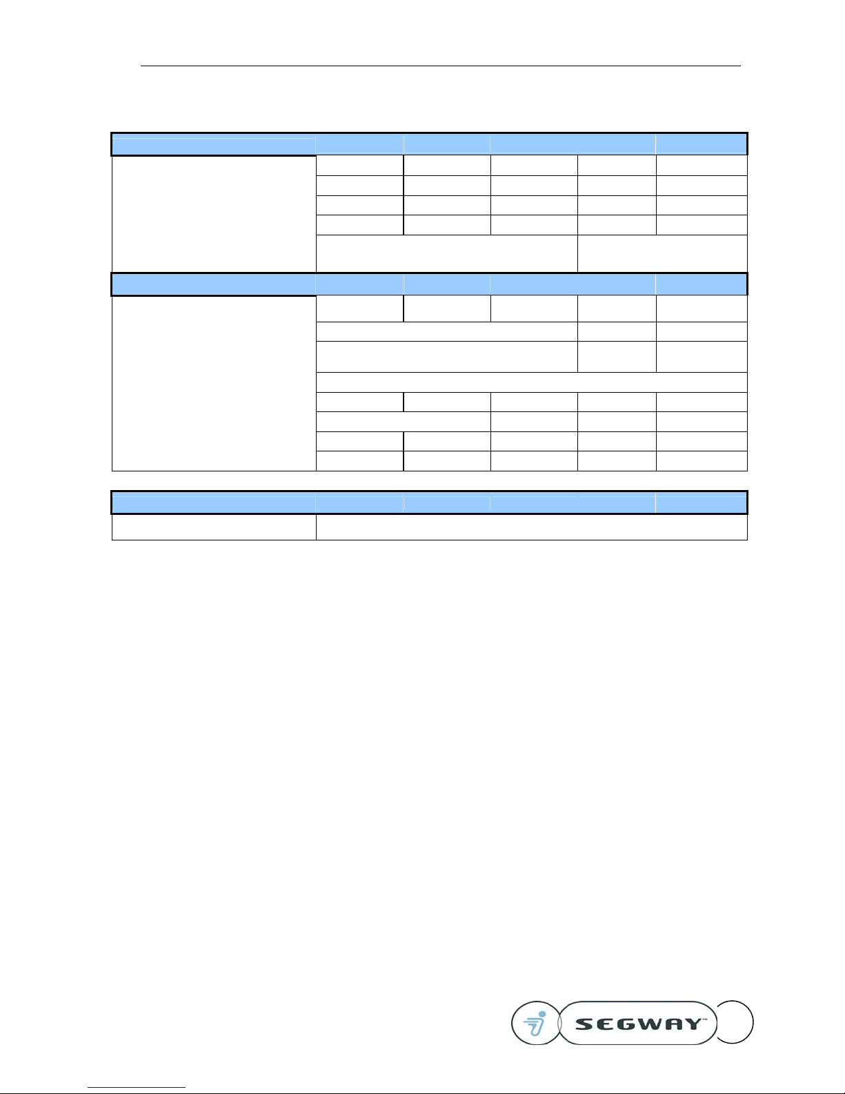
RMP Specifications
Command Interface All Models
Communications Link USB external, CAN available via internal connector
Control Industrial pushbutton interface for power and mode select
Data Update Rate 100 Hz
RMP firmware Programmed at assembly
Demo software Windows 2000 executable and source code provided
Performance RMP200 RMP200 ATV RMP100 RMP50 RMP400
Top Speed 10 mph (16 kph) 10 mph (16 kph) 6 mph (10 kph) 4 mph (6 kph) 18 mph (29 kph)
Payload 100 lbs (45 kg) 150 lbs (67 kg) 100 lbs (45 kg) 50 lbs (45 kg) 200 lbs (90 kg)
Turning Radius Zero Zero
(load dependent)
Turning Envelope 30 in (76 cm) 34 in (86 cm) 24 in (61 cm) 25 in (64 cm) 50 in (127 cm)
Maximum Climbing and Descending
Capability (traction limited) 10 degrees 5 degrees 0 degrees 45 degrees
Controller modes Dynamically stabilized and statically stable controller
modes Statically stable control mode ONLY
Batteries RMP200 RMP200 ATV RMP100 RMP50 RMP400
Battery Chemistry NiMH Li NiMH NiMH Li
Acceptable line current for charger: 90 to 260 Volts; 50 to 60 Hz
Charge Rate (72 Volt nominal) 600 milliamps per battery
Battery Life (Full Charge / Discharge Cycles) 300 to 500
Operating Temperature Range (NiMH) 32°F to 122°F (0°C to 50°C)
Operating Temperature Range (Li) 14°F to 122°F (-10°C to 50°C)
Charging Temperature Range (NiMH) 41°F to 77°F (5°C to 25°C)
Charging Temperature Range (Li) 14°F to 122°F (-10°C to 50°C)
Battery Weight (total) 19 lbs (8.6 kg) 23 lbs (10.3 kg) 15 lbs (6.8 kg) 7.5 lbs (3.4 kg) 46 lbs (20.6 kg)
Range and Energy RMP200 RMP200 ATV RMP100 RMP50 RMP400
Range under Optimal Test conditions 15 mi (24 km) 15 mi (24 km) 12 mi (19km) 6 mi (10 km) 15 mi (24 km)
Range under Good conditions 12 mi (19km) 12 mi (19km) 8 mi (13 km) 4 mi (6 km) 12 mi (19km)
Range under Severe conditions 8 mi (13 km) 8 mi (13 km) 4 mi (6 km) 2 mi (3 km) 6 mi (10 km)
Run time, stationary 8 hours
Recharge Time (from empty) ~6 hours ~8 hours ~4 hours ~4 hours ~8 hours
Environmental Capabilities All Models
Storage & Transport Temperature (no
damage to machine, <1 month) -20°C to +50°C (-4°F to +122°F)
Storage Temperature (for normal charging
and operation) +15°C to +35°C (+59°F to +95°F)
Humidity Range 0 to 95% RH (Storage); 5% to 95% RH (Operational)
Altitude Range (storage) Sea Level to 40,000 ft. (12,000 m)
Altitude Range (operation) Sea Level to 12,000 ft (3,700 m)
Version 2.0 Segway RMP – User Guide
20277-00001 aa 11
Dimensions RMP200 RMP200 ATV RMP100 RMP50 RMP400
Overall width 25 in (63 cm) 31 in (79 cm) 21.8 in (56 cm) 21.8 in (56 cm) 31 in (79 cm)
Overall height 29.5 in (75 cm) 30.5 in (78 cm) 27 in (69 cm) 27 in (69 cm) 21 in (53 cm)
Overall length 19 in (48 cm) 21 in (53 cm) 16 in (41 cm) 16 in (41 cm) 43.5 in (111 cm)
Weight 140 lb (64 kg) 160 lb (73 kg) 125 lb (57 kg) 60 lb (27 kg) 220 lb (100 kg)
Equipment mounting Multiple mounting bosses on top plate and side
support
Propulsion System
Motor Torque Constant @ motor shaft 0.071 Nm/amp 0.071 Nm/amp 0.054 Nm/amp 0.054 Nm/amp 0.071 Nm/amp
Motor Drive Peak Current, per wheel 70 amp 35 amp 70 amp
Motor Drive Continuous Current, per
wheel 24 amp 12 amp 24 amp
Gearbox Ratio 24:1
Battery Pack Capacity (total) 380 watt-hours 800 watt-hours 290 watt-hours 145 watt-hours 1600 watt-hours
Battery Pack Voltage (nominal) 72 volts 56 volts 56 volts 72 volts
Tire Diameter 19 in (48 cm) 21 in (53 cm) 16 in (41 cm) 16 in (41 cm) 21 in (53cm)
Wheel Track Width 21 in (53 cm) 24.5 in (62 cm) 18 in (46 cm) 18 in (46 cm) 24.5 in (62 cm)
Limited Warranty All Models
All parts & components 90 days

Version 2.0 Segway RMP – User Guide
20277-00001 aa 12
Assembly
All Segway Robotic Mobility Platform models may be assembled with basic hand tools. Using a
quality torque wrench is the best way to avoid stripped or broken fasteners, stripped threads, and
fasteners that vibrate loose. All fasteners should be checked periodically for tightness. The RMP
powerbase must be securely supported to prevent tipping before you begin assembling the RMP
frame.
RMP100 and RMP200
The RMP Top Plate weighs approximately 30 lbs (13.6 kg) and the RMP Ballast Plate weighs 25
lbs (11.3 kg). Use an assistant if necessary to maneuver these plates to avoid dropping them or
pinching fingers. Exploded drawings of the various RMP frames are contained at the end of this
section.
Minimum Tools needed for assembly:
• 5mm Hex wrench
• 8mm Hex wrench
Recommended tools for easiest assembly:
• Torque wrench, 3/8 drive
• 5mm Hex bit socket, 3/8 drive
• 8mm Hex bit socket, 3/8 drive
Refer to the exploded view drawing below and begin by assembling the Vertical Plates (3) to the
inside of the gearboxes. Use M6 screws (4) to fasten the Vertical Plates to the gearboxes. Do no
tighten fully at this time.
If using the Ballast Plate, set it on the top of the Vertical Plates.
Place the Top Plate (1) on top and align the holes with the Vertical Plates. Use the appropriate
length 3/8-16 screws (5) to fasten the Top Plate to the Vertical Plates. If the holes do not line up
exactly, loosen the M6 screws (4) and move the Vertical Plates.
Snug down the 3/8-16 base plate screws then snug down the M6 screws. Next, torque the Top
Plate screws to 54 N-m (40 ft-lbs) and the M6 screws to 18 N-m (13.5 ft-lbs).
Version 2.0 Segway RMP – User Guide
20277-00001 aa 13
Item Qty. Part Number Description Comments
1 1 17941-00001 RMP Top Plate
2 1 17507-00001 RMP Ballast Plate
3 2 17506-00001 RMP Vertical Plate
4 6 17512-00001 M6x1x25 SHCS Tighten to 18 N-m (13.ft-lb)
5 4 17510-00001 3/8-16x1.25 SHCS Tighten to 54 N-m (40 ft-lb)
Version 2.0 Segway RMP – User Guide
20277-00001 aa 14
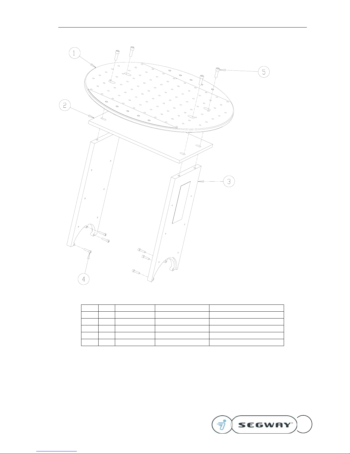
RMP50
The RMP50 is shipped fully assembled and ready for use. An exploded view of the RMP50
frame is supplied should disassembly be required.

Version 2.0 Segway RMP – User Guide
20277-00001 aa 15
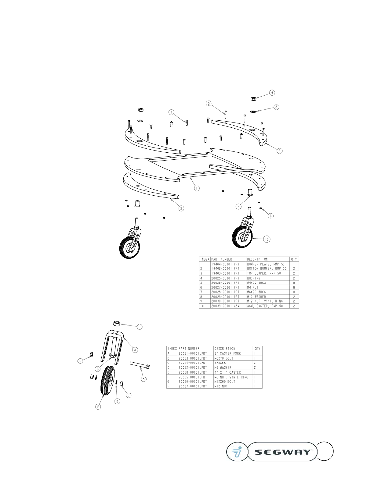
RMP400
The RMP400 is shipped fully assembled and ready for use. An exploded view of the RMP400
frame is supplied should disassembly be required.

Version 2.0 Segway RMP – User Guide
20277-00001 aa 16
!
Theory of Operation: Balancing Dynamics
Read and understand this section before starting and
operating the RMP. This information is critical to
understanding RMP operation.
The Segway Robotic Mobility Platform is a dynamically stabilized machine and has some unique
characteristics when compared to other robotic platforms. It may take some time to learn to use
these dynamics to advantage. Read and understand this entire manual before using the Segway
RMP.
Interaction With The Environment
When the RMP makes contact with other objects in the environment, the results can be counter-
intuitive at first.
If the RMP is displaced from its desired position, it will lean against the displacement force,
creating a new equilibrium position. The harder it is pushed, the more it will lean.

Version 2.0 Segway RMP – User Guide
20277-00001 aa 17
Consider the situation depicted at
the right. The resulting torque
will try to drive the machine to the
right in order to reach a level
orientation. If the wheels and
frame are free to rotate,
equilibrium will be achieved.
Pushing down on the right edge of
the RMP will cause the machine
to move to the right.
The case shown to the right is very
different from a dynamic standpoint, but
the controller cannot differentiate
between this configuration and the one
above. In this case, the RMP will
accelerate faster and faster to the right
trying to bring the machine to level
equilibrium. It will quickly trip the position
error limit of 12 feet and switch to tractor
mode.
This case also results in rapid
acceleration to the right until the RMP
can level itself.
If the RMP is driven so that it
gets one edge caught under a
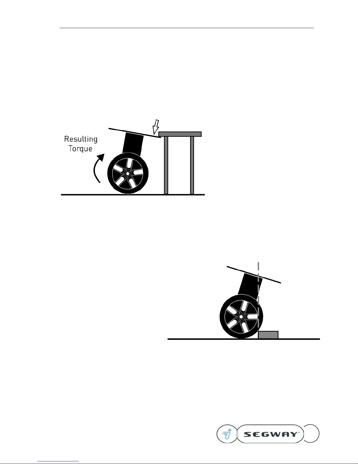
Version 2.0 Segway RMP – User Guide
20277-00001 aa 18
surface (e.g. a counter or table),
the resulting torque is also to
the right. In this case, for the
RMP to drive to the left on its
own, the edge under the table
must raise up to tilt to the left.
This will lift up on the table.
To get the RMP unstuck, an
external force must be applied to
push the RMP’s right edge down,
forcing the wheels to the left. If a
simultaneous command to drive
the RMP back is also applied, the
force required will diminish.
Alternatively, use the E-Stop to
disable the motors.
When the RMP needs to roll over an
obstacle, the CG of the system must
tilt forward over the contact point.
When the tire makes contact with
the obstacle, it stops rolling and the
frame tilts forward. Once the CG is
over the contact point with the
obstacle, the RMP will roll over the
obstacle (provided the obstacle is
small and sufficient traction exists).
Because torque is required to hold
this tilted position, there is a
tendency to overshoot the obstacle.
Approaching obstacles with a small
initial velocity typically helps in
traversing obstacles.
Version 2.0 Segway RMP – User Guide
20277-00001 aa 19
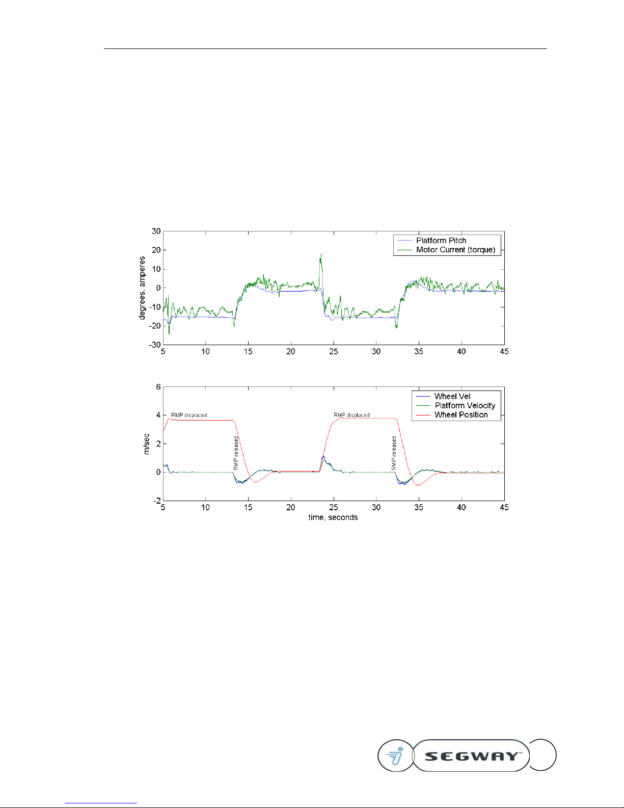
Fore/Aft Motion
The following graphs show what happens when the RMP is displaced from a resting position.
Pay attention to the following behaviors.
• The torque applied by the wheels is non-zero when the RMP is displaced from equilibrium – it
is trying to return to its start location
• It will overshoot the desired pitch and position a little before coming to rest
• The wheels travel faster (and farther) than the top plate during this oscillation
• The response will vary slightly depending on the payload and the controller gain schedule
used.
This figure shows the response of the RMP when it is displaced and released
from an equilibrium position. The velocity command is zero throughout.

Version 2.0 Segway RMP – User Guide
20277-00001 aa 20
Velocity Commands
The next series of graphs show how the RMP accelerates in response to a desired velocity
command. Note the following features in the data:
• The wheels move back slightly at the start of a forward acceleration, creating a delay
• The wheel speed overshoots the desired speed in order to stop accelerating and maintain
constant speed
• The tilt angle of the RMP is a direct function of the acceleration limit – lower acceleration
rates produce less tilt.
This figure shows the response of the RMP to a step input in the velocity
command. The commanded speed is 4 mph or 1.77 m/sec. The Acceleration
scale factor was set to 50% of maximum (8 counts)
Table of contents


