Table of Contents
Section 1: Introduction............................................................................................................ 1
Manual Overview......................................................................................................................................1
Section 2: Sphere Handling System....................................................................................... 3
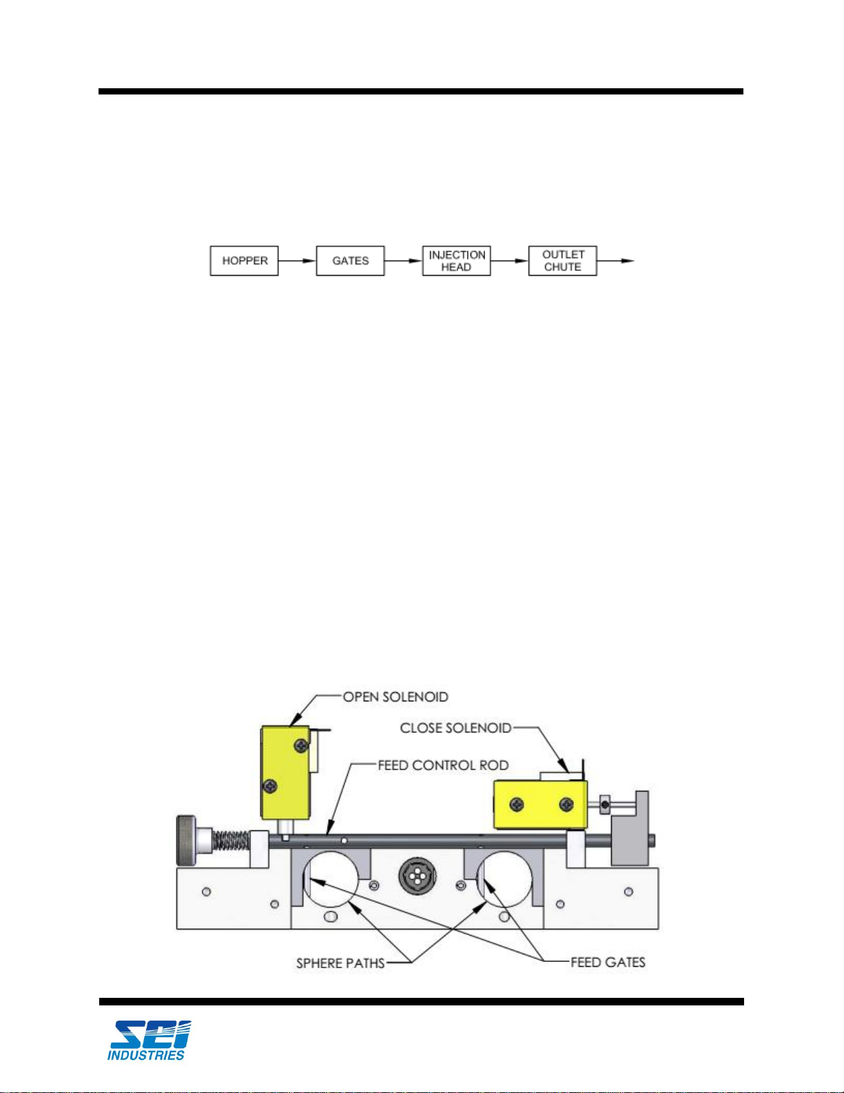
Description................................................................................................................................................3
Sphere System Components .....................................................................................................................7
Sphere System Troubleshooting .............................................................................................................16
Section 3: Glycol System .......................................................................................................21
Description..............................................................................................................................................21
Glycol System Components....................................................................................................................22
Glycol System Troubleshooting..............................................................................................................25
Section 4: Water System ........................................................................................................31
Description..............................................................................................................................................31
Water System Components.....................................................................................................................32
Water System Troubleshooting...............................................................................................................35
Section 5: Control System......................................................................................................37
Control System Operation.......................................................................................................................37
Control System Components ..................................................................................................................45
Control System Troubleshooting............................................................................................................50
Section 6: Repairs for All Systems........................................................................................75
Hopper Repairs .......................................................................................................................................75
Feed Gate Repairs...................................................................................................................................80
Injection Head Repairs............................................................................................................................88
Glycol System Repairs............................................................................................................................92
Water System Repairs.............................................................................................................................97
Control System Repairs ........................................................................................................................103
Section 7: Supplier Cross Reference ..................................................................................111
Supplier Chart.......................................................................................................................................111
Alternate Supplier Contacts..................................................................................................................114
Section 8: Warranty ..............................................................................................................115
Appendix: Safety Data Sheet ...............................................................................................117