IAI SW-4000T-10GE User manual

User Manual
SW-4000T-10GE
3CMOS Prism Linescan Camera
Document Version: 0.5
SW-4000T-10GE_Ver.0.5 _Nov.2018
Preliminary
Thank you for purchasing this product.
Be sure to read this manual before use.
This manual includes important safety precautions and instructions on how to operate the unit. Be sure to read
this manual to ensure proper operation.
The contents of this manual are subject to change without notice for the purpose of improvement.
© 2018 JAI

Contents
Notice/Warranty/Certifications............... 3
Usage Precautions.................................. 5
Features ................................................ 6
Parts Identifications............................... 7
Preparation ........................................... 11
Preparation Process............................. 11
Step 1:Installing the Software(first time
only)................................................. 11
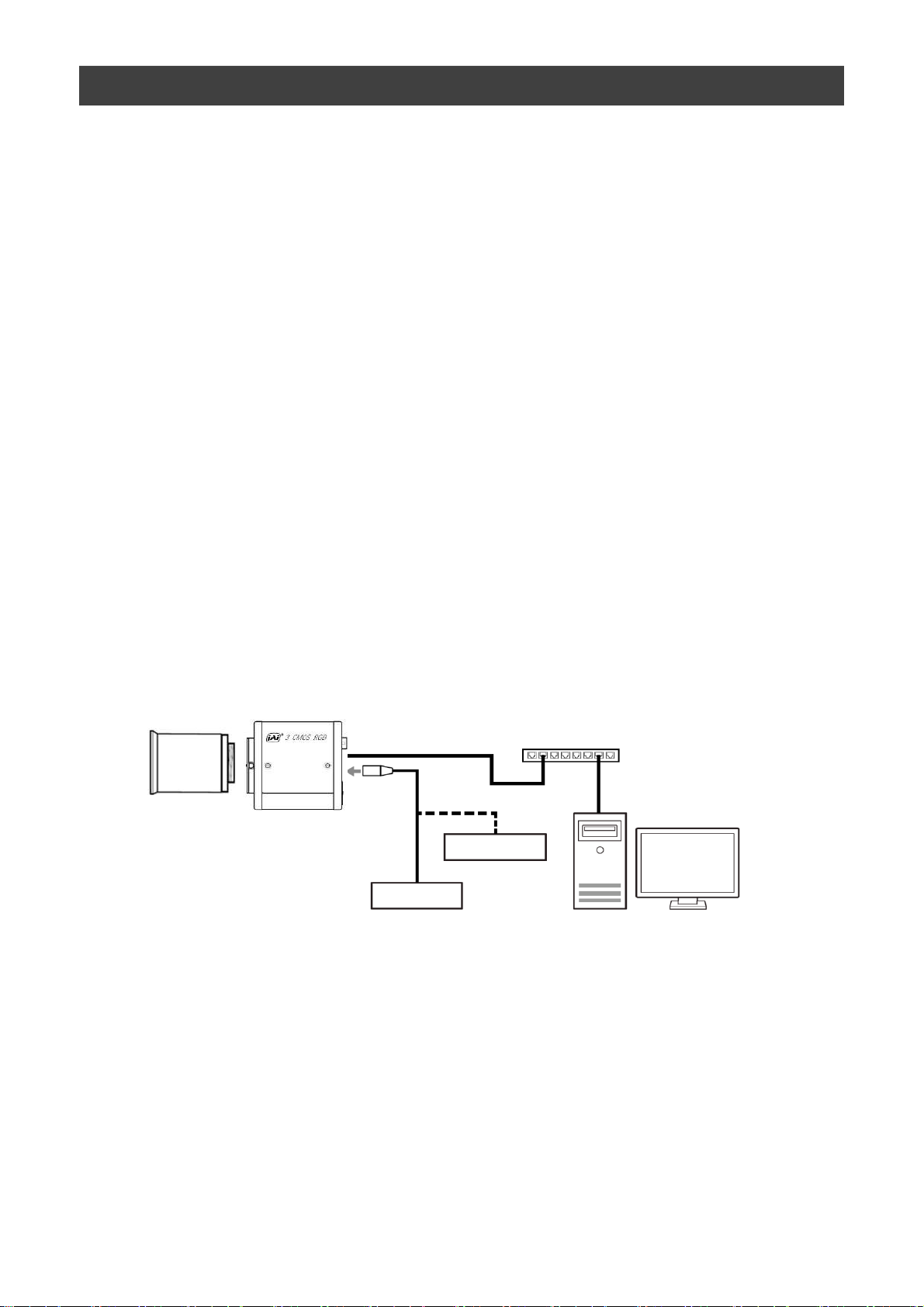
Step 2:Connecting Devices................... 12
Step 3:Verifying Camera Operation...... 14
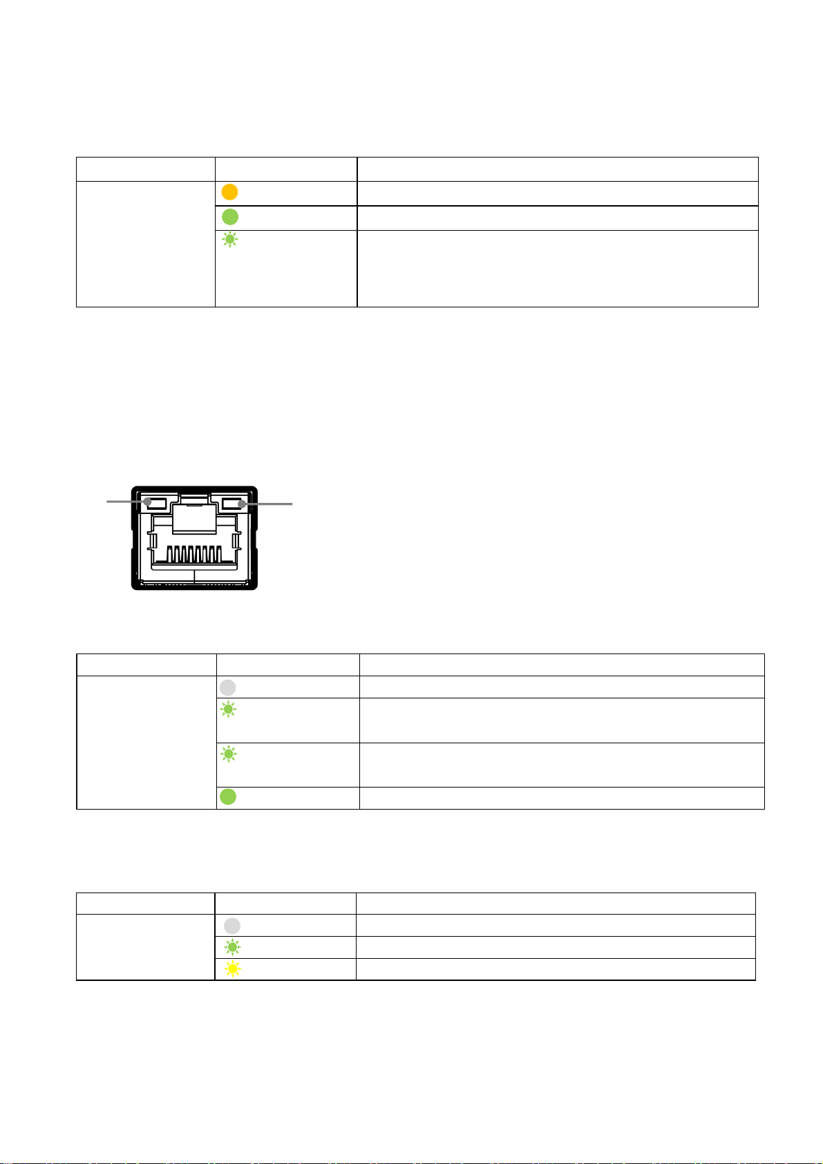
Step 4:Verifying the Connection between
the Camera and PC............................. 14
Step 5:Changing the Camera Settings.. 17
Step 6:Adjusting the Image Quality..... 18
Step 7:Saving the Settings .................. 20
Main Functions ...................................... 22
Basic Function Matrix .......................... 22
GPIO(Digital Input/Output Settings).... 22
Camera Output Formats ...................... 23
Image Acquisition Controls ................. 24
ExposureMode ..................................... 26
TriggerControl ..................................... 27
GainControl ......................................... 33
Lookup Table (LUT) .............................. 34
Gamma Function................................... 35
LineStatus............................................. 35
—2—
SW-4000T-10GE
BlemishCompensation............................ 36
ShadingCorrection.................................. 37
Binning Function.................................... 39
ROI(Regional Scanning Function)........... 39
Overlap Multi ROI Mode......................... 40
Sequencer Function............................... 42
Delayed Readout.................................... 44
ALC Function ......................................... 44
Color Space Conversion ........................ 45
Edge Enhancer, Color Enhancer.............. 46
CounterAndTimerControl Function ......... 46
VideoProcessBypassMode ..................... 48
Chunk Data Function ............................. 48
Setting List ............................................. 49
Feature Properties ................................. 49
Miscellaneous.......................................... 68
Troubleshooting ..................................... 68
Specifications......................................... 69
Frame Rate Reference............................. 71
Spectral Response................................... 72
Dimensions..............................................74
Comparison of the Decibel Display and
Multiplier Display ................................... 75
User’s Record ......................................... 76
Index........................................................ 77

Notice
The material contained in this manual consists of information that is proprietary to JAI Ltd., Japan and may only
be used by the purchasers of the product. JAI Ltd., Japan makes no warranty for the use of its product and
assumes no responsibility for any errors which may appear or for damages resulting from the use of the
information contained herein. JAI Ltd., Japan reserves the right to make changes without notice.
Company and product names mentioned in this manual are trademarks or registered trademarks of their
respective owners.
Warranty
For information about the warranty, please contact your factory representative.
Certifications
CE compliance
As defined by the Directive 2004/108/EC of the European Parliament and of the Council, EMC (Electromagnetic
compatibility), JAI Ltd., Japan declares that SW-4000T-10GE complies with the following provisions applying to
its standards.
EN 61000-6-3 (Generic emission standard part 1)
EN 61000-6-2 (Generic immunity standard part 1)
FCC
This equipment has been tested and found to comply with the limits for a Class B digital device, pursuant to Part
15 of the FCC Rules. These limits are designed to provide reasonable protection against harmful interference in
a residential installation. This equipment generates, uses and can radiate radio frequency energy and, if not
installed and used in accordance with the instructions, may cause harmful interference to radio communications.
However, there is no guarantee that interference will not occur in a particular installation. If this equipment
does cause harmful interference to radio or television reception, which can be determined by turning the
equipment off and on, the user is encouraged to try to correct the interference by one or more of the following
measures:
• Reorient or relocate the receiving antenna.
• Increase the separation between the equipment and receiver.
• Connect the equipment into an outlet on a circuit different from that to which the
receiver is connected.
• Consult the dealer or an experienced radio/TV technician for help.
Warning
Changes or modifications to this unit not expressly approved by the party responsible for FCC compliance could
void the user’s authority to operate the equipment.
—2—
SW-4000T-10GE

—4—
Supplement
The following statement is related to the regulation on “Measures for the Administration
of the control of Pollution by Electronic Information Products “, known as “China RoHS “.
The table shows contained Hazardous Substances in this camera.
mark shows that the environment-friendly use period of contained Hazardous
Substances is 15 years.
SW-4000T-10GE

Usage Precautions
—5—
Notes on cable configurations
The presence of lighting equipment and television receivers nearby may result in
video noise. In such cases, change the cable configurations or placement.
Notes on attaching the lens
Avoiding dust particles
When attaching the lens to the camera, stray dust and other particles may adhere
to the sensor surface and rear surface of the lens. Be careful of the following
when attaching the lens.
• Work in a clean environment.
• Do not remove the caps from the camera and lens until immediately before
you attach the lens.
• To prevent dust from adhering to surfaces, point the camera and lens
downward and do not allow the lens surface to come into contact with your
hands or other objects.
•Always use a blower brush to remove any dust that adheres.
Never use your hands or cloth, blow with your mouth, or use other methods to
remove dust.
Phenomena specific to CMOS image sensors
The following phenomena are known to occur on cameras equipped with CMOS
image sensors. These do not indicate malfunctions.
• Aliasing
When shooting straight lines, stripes, and similar patterns, vertical aliasing
(zigzag distortion) may appear on the monitor.
• Blooming
When strong light enters the camera, some pixels on the CMOS image sensor
may receive much more light than they are designed to hold, causing the
accumulated signal charge to overflow into surrounding pixels.This
“blooming” phenomenon can be seen in the image, but does not affect the
operation of the camera.
• Fixed pattern noise
When shooting dark objects in high-temperature conditions, fixed pattern noise
may occur throughout the entire video monitor screen.
• Defective pixels
Defective pixels (white and black pixels) of the CMOS image sensor are
minimized at the factory according to shipping standards. However, as this
phenomenon can be affected by the ambient temperature, camera settings
(e.g., high sensitivity and long exposure), and other factors, be sure to operate
within the camera’s specified operating environment.
Notes on exportation
When exporting this product, please follow the export regulations of your country
or region.
SW-4000T-10GE

Features
SW-4000T-10GE
The SW-4000T-10GE is a 3CMOS line scan camera using three 4096 pixel line sensors
mounted on a prism, for the R, G and B channels.
The camera has a 10 Gigabit Ethernet interface supporting RGB output at 8-bits or 10-
bits per channel, as well as YUV422_8 or YUV422_8_UYVY color formats.
Features overview
• Prism technology for superior color quality and better color differentiation.
• Pixel size can be switched (7.5 μ m x 7.5 μ m, 7.5 μ m x 10.5 μ m)
• Supports vertical dual-line binning, 2x horizontal binning, or both.
• High-speed scanning
maximum line rate (T.B.D.)
Pixel format: YUV422(8bit) : 140kHz
Pixel format: RGB(8bit) : 97kHz
• HSI, sRGB, Adobe RGB and XYZ color space conversion.
• Support for connection of rotary encoders.
• Excellent shock and vibration resistance.
• GenICam compliant.
Connection example:
Camera
External Trigger
AC adapter
Switching hub (PoE+ support)
PC
—8 —
Lens

Parts Identification
SW-4000T-10GE
①Lens mount (M52-mount /F-mount)
Mount a M52-mount lens, F-mount lens, etc. here.
❖ Before mounting a lens, be sure to refer to “Step 2:Connecting Devices” and confirm
the precautions for attaching a lens and the supported lens types.
—9 —
①
③
⑥
⑦
⑧
②
⑧

LED Light Status
(Lights off) No network communication
(Blinking green)
(Tx) Network communication in progress.
(Blinking yellow)
(Rx) Network communication in progress.
ACT
LED Light Status
(Lights off) Network Link is not established.
(Blinking green
slowly)
1000Base-T Link is established.
(Interval 1sec)
(Blinking green
quickly)
2.5GBase-T Link or 5GBase-T Link is established.
(Interval 200 msec)
(Lit green)
10GBase-T Link is established.
LINK
LED Light Status
(Lit amber) Camera initializing.
(Lit green) Camera in operation.
(Blinking green)
During operation in trigger mode, trigger signals are
being input
* The blinking interval is not related to the actual input interval of the external
trigger.
POWER/TRIG LED
②POWER/TRIG LED
Indicates the power and trigger input status.
LED status and camera status
SW-4000T-10GE
⑤ACT LED
Indicates the network communication status.
—10 —
④LINK LED
Indicates the link status of the network.
③RJ-45 connector
The camera supports the following Ethernet standards.
(1000Base-T, 2.5GBase-T, 5GBase-T, 10GBase-T)
Depending on the Ethernet standard to be used, the cable type and the maximum cable
length are limited.
For details, refer to "Step 2 Connecting Devices".
④
⑤

Pin No. Input/Output Signal Description
1 GND
2 Power In DC In DC 10 V ~ 25 V
3 GND
4 RESERVED
5In Opto In 1 -
6In Opto In 1 +
7 Out TTL Out 4 Line 12
8 NC
9 Out TTL Out 1 Line 1
10 In TTL In 1 Line 4
11 Power In DC In DC 10 V ~ 25 V
12 GND
Line 5
⑥DC IN/TRIG connector(12-pin round)
Connect the cable for a power supply (optional) or for DC IN / trigger IN here.
HR10A-10R-12PB(71)(Hirose Electric or equivalent )
Note
DC power supply recommends supplying power to both Pin 1 / Pin 2 and
Pin 11 / Pin 12.
SW-4000T-10GE
—11 —

SW-4000T-10GE
Recommended external input circuit diagram (reference example)
ユーザ様側 JAIカメラ
User
side
CAMERA
side
Opto In 2 の場合は、
(*1) Pin4 (Opto In 2+)
(*2) Pin3 (Opto In 2-) になります。
User Side JAI Camera Side
—12 —
*) For the constants,
see the next section
Recommended external output circuit diagram (reference example)
Standard circuit diagram example
*

User Power (VCC)
3.3 V ~24 V
Time Delay Rise TDR (us) T.B.D.
Tisc Time RT (us) T.B.D.
Time Delay Fall TDF (us) T.B.D.
Fall Time FT (us) T.B.D.
SW-4000T-10GE
—13 —
Characteristics of the recommended circuits for Opto OUT
OUTPUT LINE RESPONSE TIME
Camera
Output
Signal
Output
Line
Voltage
Please note that the recommended load resistance of OPT output is 10 kΩ (rated 1/10 W) or
more. The 270 Ω resistor shown in the circuit diagram is the MINIMUM resistance that should be
used. The response speed from On (High) to Off (Low) depends on the voltage applied to
OPT_OUT+ and the value of the load resistance. Higher load resistance results in slower
response. If the response at 10 kΩ is slower than desired, you can try reducing the load
resistance in order to increase the response speed but DO NOT go below the minimum 270 Ω
value.
Caution

Pin No. Input/Output Signal Description
1 Out TTL_OUT2 Line 8
2 Out TTL_OUT3 Line 9
3In TTL_IN2 Line 10
4 N.C.
5 GND GND
6In TTL_IN3 Line 13
7 N.C.
8 N.C.
9 GND GND
10 GND GND
⑧Camera locking screw holes (M4, 6mm depth)
Use these holes when mounting the camera directly to a wall or other structural
system.
SW-4000T-10GE
—14 —
⑦AUX connector(10-pin)
Camera side:3260-10S3(55)(Hirose Electric or equivalent )
Cable side :3240-10P-C(50)(Hirose Electric or equivalent )

Step 7
Saving the Settings
Save the current setting configurations in user memory.
Step 3
Verifying Camera Operation
Verify whether the camera is turned on and ready for use.
Step 4
Verifying the Connection between the Camera and PC
Verify whether the camera is properly recognized via eBUS SDK for JAI.
Step 5
Configuring Basic Settings for the Camera
Refer to the procedures for basic settings.
Installing the Software (first time only)
Install the software for configuring and controlling the camera (eBUS SDK for JAI) on the computer.
Step 1
Step 2
Connecting Devices
Connect the lens, network cable, AC adapter, computer, and other devices.
Step 6
Adjusting the Image Quality
Refer to the procedures for adjusting the gain, white balance, and black level as examples, and adjust the image
quality.
SW-4000T-10GE
Preparation
Preparation Process
Step 1: Installing the Software (first time only)
When using the camera for the first time, install the software for configuring and
controlling the camera (eBUS SDK for JAI) on the computer.
❖When you install eBUS SDK for JAI, eBUS SDK for JAI player will also be installed.
Download the eBUS SDK for JAI from the JAI website.
URL https://www.jai.com/jp/support-software/jai-software
Install eBUS SDK for JAI on the computer.
Caution
eBUS SDK for JAI was released in April 2018 and is the latest software for setting and
controlling JAI cameras.
When JAI SDK and eBUS SDK for JAI are installed on the same machine, conflicts can
occur. Therefore, JAI strongly recommends that JAI SDK is uninstalled before installing
eBUS SDK for JAI.
1
2
—15 —

SW-4000T-10GE
Step 2: Connecting Devices
①Lens
Camera body
③LAN
②Direct connection
(or direct connection)
④Network card
⑤PC
Switching hub
⑥DC IN/trigger IN
connection cable
or
⑦AC adapter (not supplied)
①Lens
・Attach an M52-mount lens or F-mount lens.
—16 —
The maximum performance of the camera may not be realized depending on the lens.
Caution
Note
The following formula can be used to estimate the focal length.
focal length = WD/(1 + W/w)
WD: Working distance (distance between lens and object)
W : Width of object
w : Width of sensor 30.72 mm on this camera.
②Direct connection
When mounting the camera directly to another device, for example, use screws that match the
camera locking screw holes on the camera. (M4, 6 mm depth)
For heavy lenses, be sure to support the lens itself. Do not use configurations in which its weight
is supported by the camera.
Caution

Cat5e Cat6/Cat6e Cat6A Cat7
1000Base-T 100m 100m 100m 100m
2.5GBase-T 100m 100m 100m 100m
5GBase-T 100m 100m 100m
10GBase-T 55m 100m 100m
SW-4000T-10GE
—17 —
③LAN cable
Connect a LAN cable to the RJ-45 connector.
・The camera supports the following Ethernet standards.
(1000Base-T, 2.5GBase-T, 5GBase-T, 10GBase-T)
・The longest cable length varies depending on the type of LAN cable and the Ethernet standard.
Below, the table shows the relationship diagram between LAN cable type and Ethernet standard.
Correctly select the LAN cable type according to the Ethernet standard to be used.
■About the longest cable length
④Network card
Install this in the computer that will be used to configure and operate the camera. As
the SW-4000T-10GE supports PoE+, you can also use PoE+-compatible network cards.
Refer to the instruction manual of the network card, and configure settings on the
computer as necessary.
⑤Computer
Use a computer that meets the following requirements.
オペレーティングシステム(OS):
Microsoft Windows 7/8/10 32 ビット版 /64 ビット版
CPU:Intel Core i3 以上
メモリ:
Windows 7/8/10 32 ビット版の場合:DDR3、4 GB 以上
Windows 7/8/10 64 ビット版の場合:DDR3、8 GB 以上
グラフィックカード:
PCI-Express 3.0 以上
ネットワークカード:
弊社では、Intel 社のチップを使用したネットワークカードの使用を推奨しています。
・When supplying power via PoE+, connect to a PoE+ compatible switching hub or PoE+
compatible network card.
・Refer to the specifications of the cable for details on its bend radius.
Ethernet standard
LAN cable type
-
-
Secure the locking screws on the connector
manually, and do not use a driver. Do not secure
the screws too tightly. Doing so may wear down the
screw threads on the camera. (Tightening torque:
0.147 Nm or less)
Secure manually.
Do not secure too tightly.
Caution

SW-4000T-10GE
—18 —
⑥DC IN / trigger IN connection cable
⑦AC adapter (power supply) (if necessary)
Connect the AC adapter and the round connector of the connection cable to the DC IN /
trigger IN connector on the camera.
Step 3: Verifying Camera Operation
When power is supplied to the camera while the necessary equipment is connected, the
POWER/TRIG LED at the rear of the camera lights amber, and initialization of the camera
starts. When initialization is complete, the POWER/TRIG LED lights green.
Verify whether power is being supplied to the camera by checking the rear LED.
When properly turned on
Lit green
* For details on how to read the LEDs, see “LED status and camera status” in the “Parts
Identification” section.
Step 4: Verifying the Connection between the Camera and PC
Verify whether the camera is properly recognized via Control Tool.
Connecting the Camera to Control Tool
1Startup eBUS Player for JAI
eBUS Player for JAI startup screen appears.

SW-4000T-10GE
—19 —
The connected camera is listed.
Please select one camera.
Push Select / Connect button
2Select the camera you want to configure.

SW-4000T-10GE
—20 —
3Check that the settings of the selected camera are displayed.
Push the Device control button.
The screen shown below will be displayed. In this window you can adjust various
settings of the camera.
This completes the procedure for verifying whether the camera is properly recognized and
whether control and settings configuration are possible.

Item Setting value / selectable range
Trigger Mode On
Trigger Selector Line Start
Trigger Source Any
Trigger Activation LevelHigh (high-level duration),
LevelLow (low-level duration)
Exposure Mode TriggerWidth (control via trigger width)
Item Setting value / selectable range
Trigger Mode On
Trigger Selector Line Start
Trigger Source Any
Trigger Activation
Rising Edge (rising edge of input signal),
Falling Edge (falling edge of input signal)
Exposure Mode Timed (control via exposure time)
Exposure Time Varies depending on settings.
SW-4000T-10GE
—21 —
Step 5 Configuring Basic Settings for the Camera
1Set [Exposure Mode] to [Timed].
2Specify the exposure time in [Exposure Time].
3Set [Trigger Mode] to [On] and set [Trigger Selector] to [Line Start].
4If necessary, change the [Trigger Source], and [Trigger Activation] settings.
When Controlling the Exposure Time Using Specified Exposure Times
Configure the settings as follows.
■Control via External Triggers
When Controlling the Exposure Time Using the Pulse Width of the Trigger
Input Signal
Configure the settings as follows.
1Set [Trigger Mode] to [On] .
2Set [Exposure Mode] to [Trigger Width] .
3If necessary, change the [Trigger Source] and [Trigger Activation] settings.

Item Setting value / selectable range
Exposure Mode Off
Item Setting value / selectable range
Trigger Mode Off
Exposure Mode Timed (control via exposure time)
Exposure Time Varies depending on settings.
Acquisition Line Rate Varies depending on the PixelFormat and Link speed.
SW-4000T-10GE
—22 —
1Set [Exposure Mode] to [Timed].
2Set [Trigger Mode] to [Off].
3Specify a line period slower than the exposure time in [Acquisition Line Rate].
4Specify the exposure time in [Exposure Time].
When Controlling the Exposure Time Using Specified Exposure Times
Configure the settings as follows.
■Control Without External Triggers
When Not Controlling the Exposure Time
Configure the settings as follows.
The exposure will be performed with an exposure time equal to 1 / line rate.
* The exposure time specified in [Exposure Time] will be disabled.
Table of contents