SEIKAKU TECHNICAL GROUP DCS-100 User manual

Digital Conference System
3
1. Introduction
2. Features
3. Usefull Data
4. Panel Description
5. Rear Panel Description
6. PC Control
7. Sub-device Description
8. Chairman Device & Delegate Device
9. PC Software Editor
10. System Application Diagram
11. Block Diagram
12. Electrical Specifications
4
4
4
5
7
9
16
17
18
21
23
24
under the EM disturbance, the ratio of signal-noise may be changed above 3dB.
* The mixer for professional use. They can be used in following electromagnetic environment:
residential, commercial and light industrial, urban outdoors.
They are the apparatus not intended for rack mounting.
* The peak inrush currents equal to 8.33 A.
*This device complies with part 15 of the FCC Rules. Operation is subject to the following two
conditions: (1)this device may not cause harmful interference, and (2)this device must accept any
interference received, including interference that may cause undesired operation. Changes or
modifications not expressly approved by the party responsible for compliance could void the user's
authority to operate the equipment.
NOTE: This equipment has been tested and found to comply with the limits for a Class B digital
device, pursuant to Part 15 of the FCC Rules. These limits are designed to provide reasonable
protection against harmful interference in a residential installation. This equipment generates,
uses and can radiate radio frequency energy and, if not installed and used in accordance with the
instructions, may cause harmful interference to radio communications. However, there is no
guarantee that interference will not occur in a particular installation. If this equipment does cause
harmful interference to radio or television reception, which can be determined by turning the
equipment off and on, the user is encouraged to try to correct the interference by one or more of
the following measures:
-- Reorient or relocate the receiving antenna.
-- Increase the separation between the equipment and receiver.
-- Connect the equipment into an outlet on a circuit different from that to which the receiver is
connected.
-- Consult the dealer or an experienced radio/TV technician for help.

Introduction
Features
Usefull Data
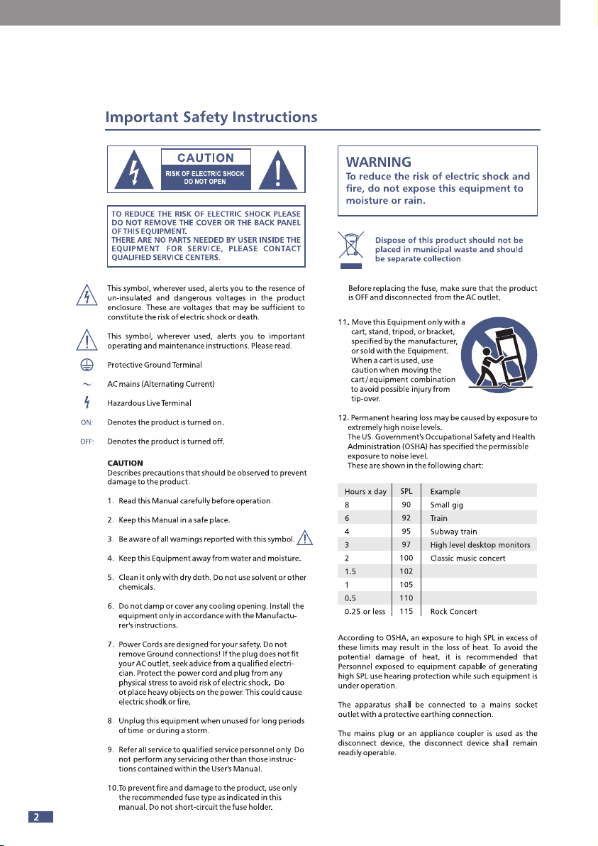
Please write your serial number here for future reference.
4
Thank you for purchasing digital conference system. It is a new generation of
advanced digital conference system, all data and audio are used digital signal
processing. The system includes the host, chairman machine, attendance machine,
expansion machine and multiple video switcher. Software includes the scene preset,
microphone management, voting management, feedback suppression, audio
equalization and other functions.
It is recommended that you carefully read the manual before using it to familiarize
yourself with its features, applications, and proper connection. Thank you again for
purchasing our products.
- Built-in digital feedback suppressor.
- Integrated recording function, the recording data can be stored in external USB
device at real-time.
- Expand maximum to 72 pcs.
- Discussion mode can be configured by software.
- Optional module expansion interface: Dante module.
- Voting function.
- Simultaneous interpretation function.
- Report function.
- Camera-tracking function.

4
Panel Description
5
(2)
(4) (6) (11) (12)
(3) (8) (1)(5) (9) (7) (10)
1) Speaker volume control
Short Press: Rotate left and right to adjust the volume, short press has no function.
Long Press: Lock the device, any operation in the locked state requires a password to
unlock.
2) Discussion device volume control
It is used to adjust the output volume of the chairman machine’ and attendance
machine’ speakers and headphones in the main interface.
It also can be used to move the cursor left and right in the EQ adjustment interface.
Monitor:
Short press: Rotate left and right to adjust the volume, short press has no function
Long Press: Perform device password change when unlocked
Password setting: long press monitor to enter the password setting interface
(four-digit password). Move the monitor cursor to select the appropriate position,
turn the speaker knob to select the number, short press of the speaker knob to
confirm. After the whole password is set, short press the speaker knob to confirm the
password. Long press the speaker knob to lock system, when locked, pressing any
button on the panel is required to enter the password in order to unlock the
operation.
3) Voting mode/Discuss mode selection button
Long press: Entering voting mode, there are three options for agreeing, disagreeing,
and dropping. Short press the play/pause button and the host will start voting.
Short press: Switch the discussion modes: 1 person, 3 persons, 6 persons, 9 persons
and all.
4) Feedback suppression button
Long Press: Initialize FBC related filter configuration
ShortPress: Turn on or off the Feedback function. Turn on the Feedback function, its
backlight will light up, and the feedback suppression function will turn on to suppress
howling caused by the microphone.

Panel Description
4
6
5) USB port
Insert USB, it can store meeting recording, play meeting recording and background
music. Support format: MP3, WMA, AAC, WAC.
6) LCD
This LCD screen displays information such as volume, recording, and discussion mode,
etc.
7) Play / Pause
Pressing this button can start playing and pause playing.
This button can bypass all EQ high and low pass, press again can restore to the state
before Bypass in EQ adjustment interface.
8) Stop button
Short Press: Stop playing audio files when USB is inserted.
Long Press: Fire alarm function.
9) EQ/Pre recording button
Long press: Enter EQ setting interface.
Short press: Start to play the previous recorded recording in the main interface.
10) Next recording/Up button
Short Press: When the USB is plugged in, play the next audio file.
Long Press: Switch FIFO function.
11) Record/ Exit button
In the main interface, press this button to start recording the audio. Press again to
end the recording and save the audio. In other interfaces, press this button to exit
the current interface and return to the main interface.
12) Repeat/Down button
Press this button in the main interface to repeat the recording. Press again to cancel
loop playback.
In the EQ interface, press this button to move the cursor down.
Short press: return key.
Long press: switch. simultaneous interpretation function.
13) Combination keys
1. Discuss Mode+Feed Back The combination buttons are long press to enter the
factory button detection.
2. Stop+Next+Repeat The combination of buttons are long press to restore all
online machines in the unlocked state.
5
Rear Panel Description
7
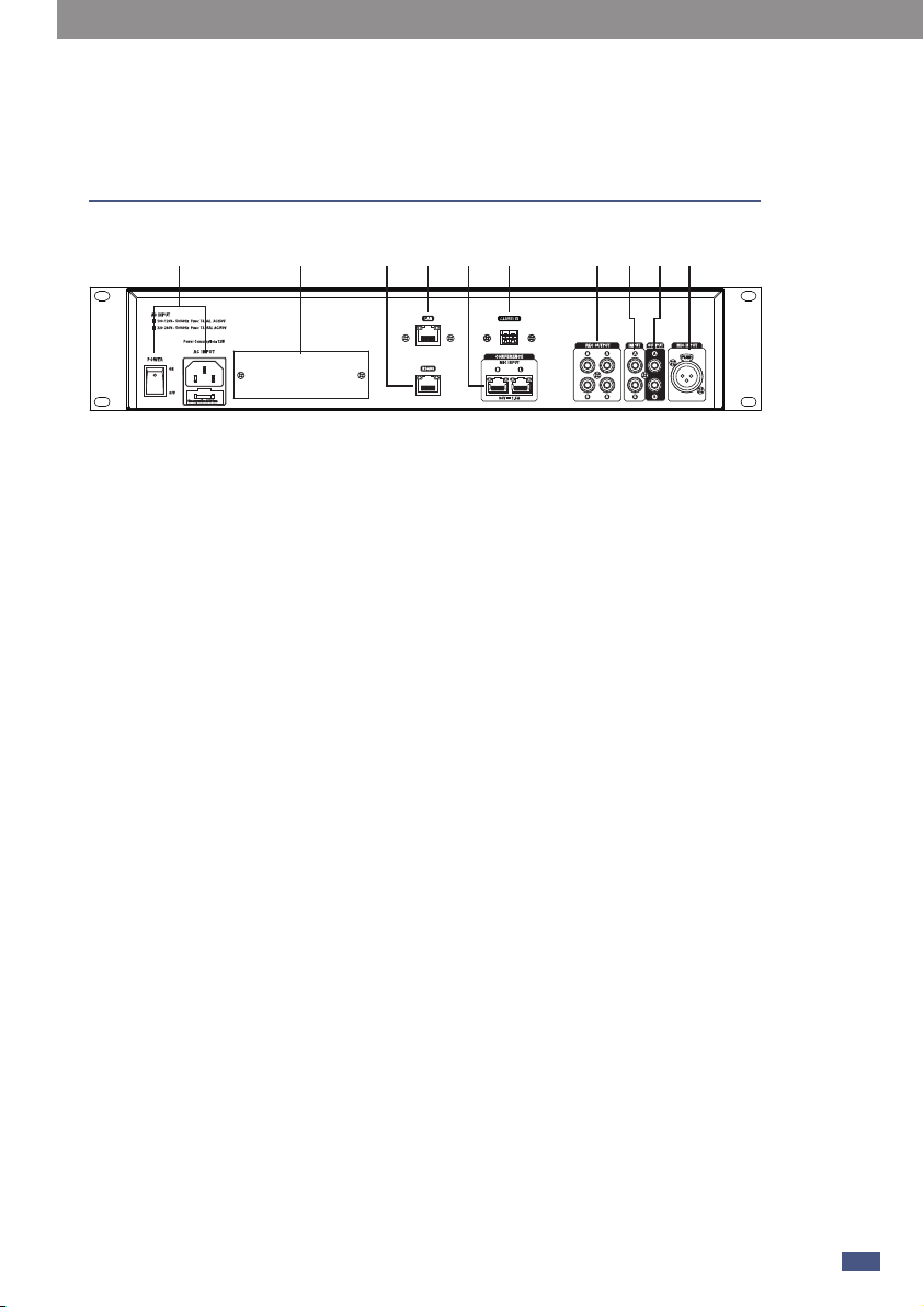
(1) (4) (2) (9)(5) (6) (7) (6) (8)(3)
1) Power outlet and switch
It is used to turn on or off the device.
Note: before operating, observe the factory voltage, select the appropriate voltage.
2) Ethernet port
This port is the Ethernet port for connecting network cables.
3) RS485
It is used for multiple video tracking switching.
4) Optional module
Connect to the 2 IN 2 OUT DANTE module, and can connect to the MATRIX SYSTEM.
5) Discussion device jack
It is used for connecting to the chairman machine and the attendance machine.
6) RCA audio output
Used for connecting external input devices.
7) RCA audio input
It is a fire alarm signal input interface. When the fire alarm function is not turned on,
the input interface signal will be directly mixed and output; when the fire alarm
function is turned on, the input interface signal is not output in normal state, only
when the device receives the fire alarm information from the emergency system
Output only when At this time, other inputs will be blocked, and the fire alarm signal
will be played at the maximum power of the device.
8) Microphone input
It is a simultaneous interpretation interface, generally used as the input source of
simultaneous interpretation, which needs to be used with the simultaneous
interpretation selection switch on Chairman/Delegate.
Rear Panel Description
5
8
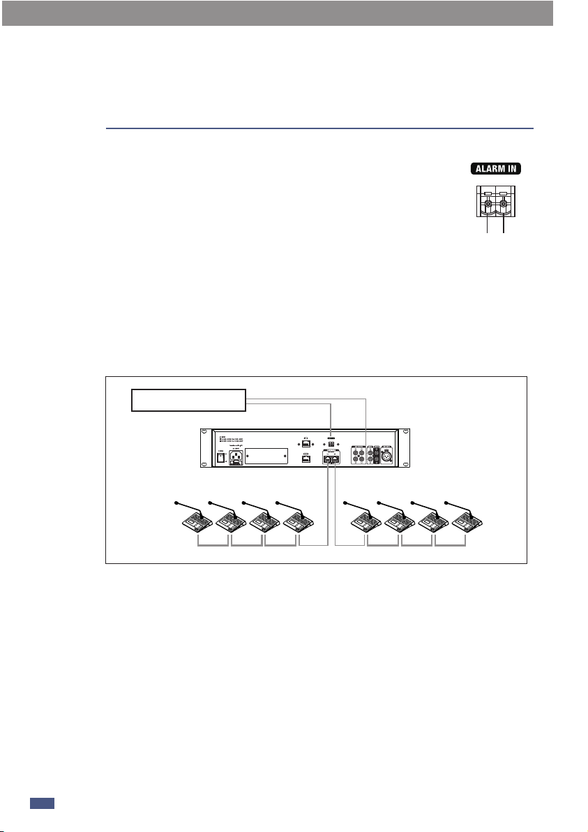
9) Alarm In
When this port receives a continuous alarm signal from a third-party
system (such as the Voice Alarm System), the conference system will
automatically turn off all microphone input and turn on the alarm
broadcast input. At this time, the alarm system will play the alarm at
the maximum volume. The words “Alarm input...” are displayed on
the screen, as shown in the screenshot below. When the continuous
alarm signal is disconnected, the conference system will return to
normal use status.
a. GND
b. ALARM IN
The alarm is triggered when the TX receives a low level.
(b)(a)
Voice Alarm System
Connection diagram:
PC Control 6
9
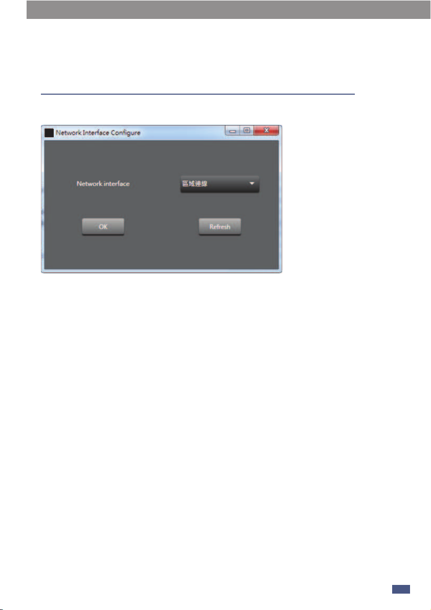
1. Firstly, after the device is connected successfully , then open the PC software.
Refresh: Refresh the network connection status.
OK: After the language/network connection is successful, you can enter the software
interface.
2. After entering the software, the status light (green) in the upper left corner will
automatically light up, indicating that the communication is normal. The status light
(gray) indicates communication failure. If manually disconnected, please click connect
after 3 seconds.
-Lock: Click to lock.
Attention:
Super administrator password is“9825”.The super administrator password cannot be
changed after leaving the factory and is unique.It can be used to reset the system
password to "0000".
Step:
1) After the system is locked, enter the system password to unlock it, and an
additional prompt will appear when the password is entered incorrectly.
2) Follow the additional prompts and press [play] to enter the reset interface.
3) Enter the super administrator password to confirm success and exit.
4) Or when setting a new password by entering the old password, press [play] to enter
the reset interface.
5) Enter the super administrator password to confirm success and exit.
-Language:Chinese/English.
PC Control
10
6
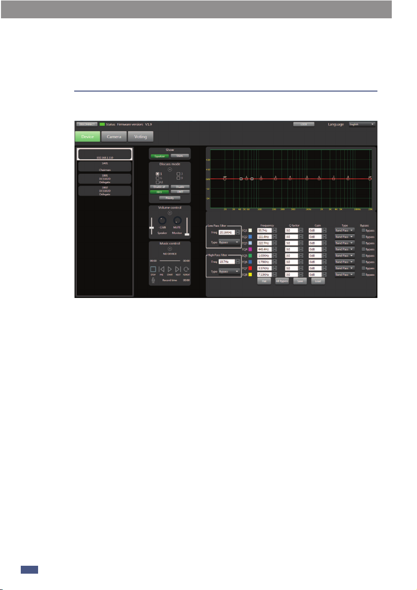
2.1 Interface switching
1-Equalizer: Click this button to display the EQ debugging interface
There are 8 EQ points on this page, you can debug EQ parameters including Low/High
filter/type/Freq, Q/Gain, etc.
1) High/low pass type filter: 19.7Hz~20.16kHz.
2) High/low pass type: BW6/BW12/BS16/lk48 etc.
3) Frequency: 19.7Hz~20.16KHz
4) Q: There are 8 frequency points, the interval is 0.4~128.
5) Gian: -12dB~12dB
6) Type: Peak/Low Pass/High Pass
7) Bypass: The signal is not processed here and jumps directly to the next module.
8) Default: Click this button to restore the parameters to default.
9) All Bypass: Shield all frequency points.
10) Save preset saves the current parameters to the device.
11) Load preset: Load the preset from the local to the device.

2.2 User
User: Click this button to display the member list. Enter the following interface (2.2)
Black speaker means the microphone is active
Red speaker means the microphone is off
A red speaker with an exclamation mark indicates that the microphone is
disabled.
Double-click the name under the avatar to modify it.
PC Control 6
11

2.3 Discuss mode:
1) 3 person: Allow up to 3 people to speak at the same time.
6 person: Allow up to 6 people to speak at the same time.
9 person: Allow up to 9 people to speak at the same time.
2) All: Everyone can talk at the same time.
Disable All: Click Disable All would mute all device except chairman device.Muted
devices will not be able to vote. You can click Disable All again to cancel the mute
status of all devices.
3) Disable: After clicking the muted machine, click the portrait icon to unmute the
corresponding device outside the chairman machine, and click the muted device to
remove mute status. You can click Disable again to turn off the select mute mode.
Clicking the portrait icon will only activate or deactivate the microphone.
4) FIFO: First Input First Output.
5) LIMIT: Answer mode.
6) Priority: Click Priority button that chairman has priority to speak.
Attention: This button has no function when you did not connect the chairman
device.
2.4 Volume Controller
1) Speaker: It was used to control the volume of speaker.
2) Monitor: It was used to control the volume of microphone.
2.5 Music Control
1) Show song name.
2) Show the current playback progress of the song
3) STOP:Press this button to stop the song.And it start from 00:00 when you press
STOP again.
4) Pre: play next song.
5) Pause/Start: Pause / play the song.
5) Next: play next song.
6) Repeat: single circle.
7) Record: Press record icon.it would recording at once. The routing often saves to
USB.
Attention:
1. Please insert USB before you use MUSIC CONTROL.When a mobile storage device is
inserted, the host will detect the device and read the storage deviceMP3 files. Click the
record button to stop playing music and start recording.
2. If the storage device cannot be detected, the power supply may be insufficient.
Please try to replace the storage device. If the device is severely stuck, please check
whether your storage device contains non-MP3 files with large contents (it is
recommended to use an empty storage device to put the files you want to play).
PC Control
12
6
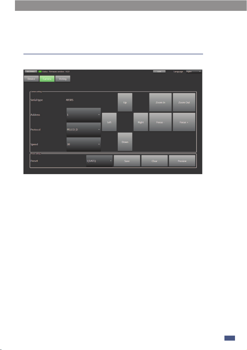
2.6 Camera
1) Serial Port: 485RS
2) Camera address: Connect to only 1 camera and selection of address set only be
fixed 1 as above image.
3) Protocol: Protocol type selection.
4) Speed: Camera rotation speed setting
5) U P/ Left / Right / Down: Camera rotation direction.
6) Zoom In/Zoom Out/ Focus-/Focus+: Long press to adjust, release to stop.
7) Preset: Select the attending machine (its ID) to save the preset of the above settings.
8) Save: Click the button to save current preset.
9) Clear: Click Clear to clear the preset.
10) Preview: Preview the preset.
6
PC Control
13
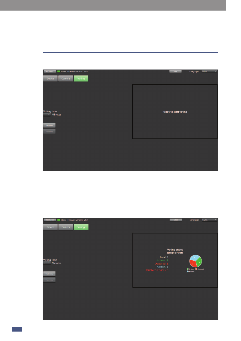
2.7 Voting
1) Voting Time: Here you can choose the voting duration, the interval is 1~18
minutes.
2) Start Voting: After choosing the voting duration, click Start voting to start voting.
At the same time, the voting time countdown appears in the box on the right.
3) Stop Voting: Click the button to stop vote.
Function Example:
14
6PC Control

1min voting as example:
1) Set voting time to1 minute.
2) Click to start voting.
3) The time automatically enters a countdown. The speaker needs to press
(double-click) Agree / Disagree / Drop on the touch screen of the chairman / delegate
device.
4) Wait for finished the voting or click Stop voting to completed the voting.
5) The box on the right shows the statistics of the poll results.
PC Control 6
15

Sub-device Description
16
7
Power: LED power on indicator
Extender
This device can be plug and play, mainly used in small and medium-sized
meeting places.
Two-way expansion function, one way to expand 16 units.
1) Output: Network cable output, connect to the input of the next delegate.
2) Input: Network cable input, connect to the LINK output of an delegate.
3) AC Input: Power socket.
(1) (2) (3)

The difference between the appearance of the
Chairman chairman unit and the Delegate
attending unit is that Chairman has a Priority
button (7) but Delegate does not have this
button. Put two kinds of machines together to
explain and introduce:
1. Microphone interface
The interface in the middle is used to connect
a gooseneck microphone. Please note that if
you need to replace it, please use a gooseneck
microphone with LED, otherwise it may cause
unpredictable results. (Pin 1 is grounding, pin
2 is LED power supply, pin 3 is signal, and
there is a label above the socket.)
2. LCD screen
Used to display the current speaking status
and recording information.
3. Agree
Touch Agree on the voting interface, and then click to confirm the selection.
4. Drop
Touch Drop on the voting interface , and then click to confirm the selection.
5. Disagree
Touch Drop on the voting interface , and then click to confirm the selection.
6. Volume adjustment
Touch "+" to increase the earphone volume.
Volume adjustment
Touch "-" to decrease the earphone volume.
7. Priority button
When the chairman machine is set to be the discussion device, touch "Priority" to cover
the microphone of all other attendees and give priority to speaking.
8. MIC
Press this key on the main interface to activate and deactivate the microphone.
9. Conference system expansion
These two interfaces are used to connect multiple discussion devices. For example, the
left interface connects to the previous device, the right interface connects to the next
device, and so on.
Chairman Device & Delegate Device 8
17
9
1
2
3
4
5
6
7
8
6
Chairman / Delegate Side panel
Simultaneous interpretation function:The MIC INPUT on the rear panel is the
simultaneous interpretation interface, which
is generally used as the simultaneous
interpretation input source. It needs to be
used with (10) earphones and (11) simultaneous interpretation selection switches on
the Chairman / Delegate.
1-When the simultaneous interpretation function is turned on:-Turn the switch to the "2" position, the audio source is selected as "simultaneous
interpretation input", at this time the earphone (10) has only simultaneous
interpretation input source.
2-When the simultaneous interpretation function is turned off,
-Turn the switch to the "1" position, and the audio source is selected as "mixed audio".
At this time, the audio heard by the earphone (10) is played by the microphone, MP3,
RCA input, and simultaneous interpretation input mixed audio source.
18
8Chairman Device & Delegate Device
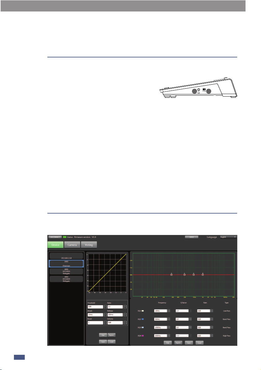
9PC Software Editor
10 11
Chairman Device
Delegate Device
The compressor can reduce the dynamic range of the signal, for example: input signal
with a dynamic range of 110db. When the compressor is output again, the new
dynamic range becomes 70dB.
1. Threshold: Touch the button to set the compression trigger level of the selected
channel. If the signal amplitude exceeds the trigger level, the compressor will work to
reduce the signal level. The trigger level setting range is -42dB~0dB.
2. Compression ratio: Touch this control to adjust the compression ratio of the
selected channel. The range is: 1:1~12.0:1. This ratio sets the slope of the
compression, that is, the ratio of the output level to the input level. For example, if the
ratio is set to 4:1, any signal higher than the trigger level will be It will be compressed
at a ratio of 2:1. This means that for a signal above the trigger level, for every 4dB
increase, the compressed output only increases by 1dB, and the ratio ranges from
10:1 to 1:1 until limited.
3. Attack: Touch this control to set the compression start speed of the selected
channel. Start to set the speed at which compression will act on the signal. The
starting time setting range is: 0.08ms~100ms.
4. Release: Touch this button to set the compression release time of the selected
channel, how long it takes to release the signal below the trigger level to return to its
normal gain, the release time is set to: 10ms~5000ms.
9
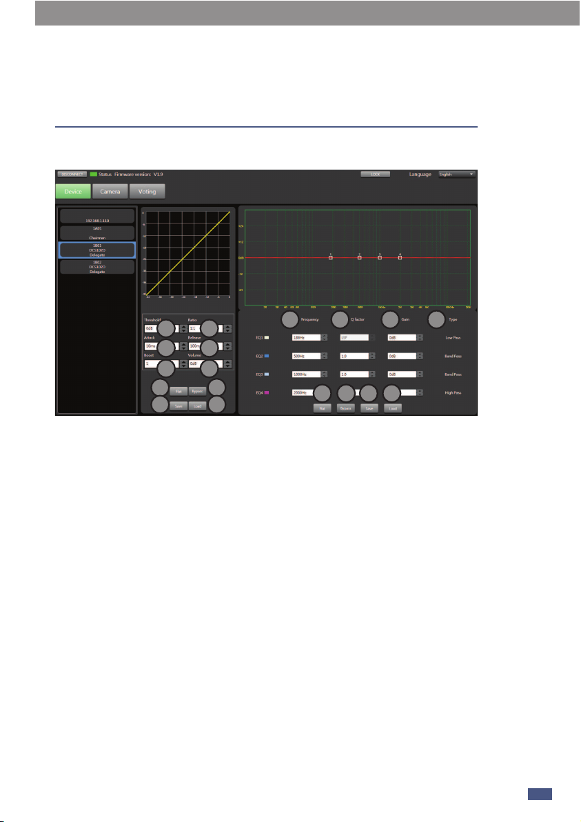
PC Software Editor
19
1 2
3 4
5
7 8
9 10
11
15 16 17 18
12 13 14
6

5. Boost: Enlarge the field of view in this area.
6. Volume: Set the decibel value of compression.
7. Flat: Click this button to restore the default parameters.
8. Bypass: After the signal here is not processed, skip directly to the next module.
9. Save: Save the preset to the device.
10. Load: Load the preset from the PC to the device.
Regard to EQ:
11. Freq: Touch this button to set the center frequency of the EQ low / mid-low /
mid-high / high band. The center frequency is the midpoint of the passable frequency.
It is between the lower and higher cut-off frequency (used to define the frequency
limit). The center frequency can be set in the range: 20Hz-20KHz.
12. Q: Touch this button to set the Q value of the low / middle-low / middle-high / high
frequency band of EQ. The range is 1.0~20. The Q value is the ratio of the center
frequency to the broadband. If the center frequency does not change, the broadband
and Q are inversely proportional, That is, increase the Q value and narrow the
bandwidth.
13. Gain: Increase the volume in dB.
14. Type: Type indicates the selected filter type, and different types indicate different
waveforms and different filter frequency ranges.
15. Flat: Restore the preset parameters currently set to the default parameters.
16. Bypass: Press this key, this area function is invalid.
17. Save: Save the current preset parameters.
18. Load: Load the preset from the PC to the device.
20
9PC Software Editor
Table of contents
Other SEIKAKU TECHNICAL GROUP Conference System manuals


