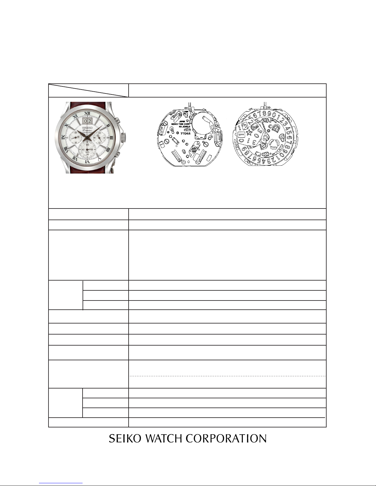
Seiko 7T04A Quick start guide

PARTS CATALOGUE/TECHNICALGUIDE
Cal. 7T04A
[SPECIFICATIONS]
Cal. No.
Item
Interval of hands movement
Driving system
Additional function
Loss/gain
Regulation system
Gate time for rate measurement
Power
supply
Battery No.
Battery voltage
Battery life
Number of jewels
1/21
Crown
operation
Normal position
1st click position
2nd click position
Current consumption
Coil resistance
1 second
0 jewel
Stepping motor, 3 pieces
• Stopwatch function
60-minute stopwatch in 1/5-second increments.
• Battery life indicator (The small second hand moves at two-second
intervals.)
• Second hand stop function
• Electronic circuit reset function
• Big date indicator function
4002700 (COIL BLOCK and COIL BLOCK FOR SECONDS COUNTING)
2.10 - 2.70 KΩ
Use 10-second gate.
SEIKO SR927SW
Nil
1.55 V
Approx. 5 years
7T04A
• 3 hands (hour, minute,
and small second
hand)
• 24-hour indicator
• Big date indicator
4002711 (COIL BLOCK FOR MINUTE COUNTING)
1.80 - 2.40 KΩ
Free
Date setting(clockwise)
Time setting, hand position adjustment / resetting the circuit
Monthly rate: Less than 15 seconds (worn on the wrist at the tempera-
ture between 5 and 35)
• Diameter
Outside: Ø 27.6 mm Casing: Ø 27.0 mm
• Height: 4.93 mm
Movement: Less than 1.10 μA
Circuit block: Less than 0.20 μA

SPECIFICATIONS
2/21
Cal. 7T04A
Cal. 7T04A is a new basic calibre which has a big date indicator function, but the basic movement
structure of Cal. 7T04A is similar to the previous Cal. 7T Series watches, and the knowledge and
technique you have gained in handling the previous Cal. 7T Series watches will come in handy
when you repair Cal. 7T04A.
When repairing, however, you are requested to have full knowledge of the features characteristic
of these watches and strictly observe the repairing and checking instructions provided in this
guide so that the watches will be repaired correctly.
FEATURES
This is the multi-display analogue watch featuring a stopwatch function.
●The time is indicated by the 24-hour, hour and minute hands, and a small second hand.
●The stop watch can measure up to 60 minutes in 1/5-second increments. After 60 minutes,
it will start counting again from “0” repeatedly up to 12 hours.
●Measurement performance
Displays the elapsed time with the 2 designated STOPWATCH hands.
Measures up to 60 minutes in 1/5-second increments.
●Button operation (Crown position: Normal position)
Button A: START/STOP
Button B: SPLIT/SPLIT RELEASE/RESET
1. STOPWATCH FUNCTION
Cal. 7T04A
A
B
a b c
CROWN
Hour hand
Minute hand
STOPWATCH 1/5-second hand
STOPWATCH minute hand
Small second hand
Big date indicator
a: Normal position
b: First click
c: Second click
24-hour hand

SPECIFICATIONS
3/21
Cal. 7T04A
After installing the battery, pull out the crown to the second click position. And then follow the
instructions below to correct the hand positions and set the time.
NECESSARY PROCEDURE AFTER BATTERY CHANGE
Pull out to the second click position when the small second hand is at
the 60 seconds position. The small second hand stops on the spot.
Turn to set the main time. * Check that AM/PM is correctly set.
Crown
Crown
Push back in to the normal position in accordance with a time signal.
Crown
Button A
Button B
Button A
Button B
Press Button A for longer than 2 seconds.
The STOPWATCH minute hand turns a full circle.
Press Button B to set the STOPWATCH minute hand to the
“0” position. It moves quickly if button B is kept pressed.
Press Button A for longer than 2 seconds.
The STOPWATCH hour and second hand turns a full circle.
Press Button B repeatedly to reset the STOPWATCH
second hand to the “0” position (12:00). It moves quickly
if button B is kept pressed.
● Standard measurement
Button A
START →Button A
STOP →Button B
RESET
● Split (intermediate) time measurement
Button A
START →Button B
SPLIT
Button B
SPLIT RELEASE
→ → → Button B
RESET
Button A
STOP
● A ccumulated elapsed time measurement
Button A
START →Button A
STOP
Button A
STOP →Button B
RESET
→Button A
RESTART … →
Measurement and release of the split time can be repeated by pressing button B.
Restart and stop of the stopwatch can be repeated by pressing button A.
● Measurement of two competitors
Button A
START
Button B
RESET
Button B
FINISH TIME OF FIRST
RUNNER
Button A
SECOND RUNNER
FINISH
→ →
Button B
FINISH TIME OF
SECOND RUNNER
→ →
●Measurement functions
Accumulated elapsed time measurement and split time measurement are available.

Cal. 7T04A
PARTS LIST
4/21
2 DATE DIAL FOR
TEN’S DIGIT
0878B95
3 DATE DISK GUARD
SCREW (2pcs.)
0012354
4 DATE DISK GUARD
0808522
5 DATE JUMPER SCREW
FOR UNIT’S DIGIT
0012354
6 DATE DISK FOR
UNIT’S DIGIT
0878B93
7 DATE JUMPER FOR
UNIT’S DIGIT
0810504
8 DATE JUMPER FOR
TEN’S DIGIT
0810505
1 DATE DIAL SCREW
FOR TEN’S DIGIT
0012354
DATE DRIVING WHEEL
0802515
9
Lubricating of some parts is shown in "II. REMARKS ON DISASSEMBLING AND REASSEMBLING."
Disassembling procedures Figs. : 1 62
Reassembling procedures Figs. : 62 1
Remarks on removing the Setting stem
To remove the SETTING STEM when taking
out the movement from the case or while
disassembling the parts during repair work,
be sure to pull out the crown to the first
click, and then, remove the SETTING STEM
while pushing the setting lever. Refer to
page 9 for further details.
[24 HOUR INDICATOR MECHANISM]

PARTS LIST Cal. 7T04A
5/21
11 CALENDAR PLATE
0712505
12 CALENDAR CORRECTOR
WHEEL
0737505
13 24 HOUR WHEEL
1002534
14 INTERMEDIATE WHEEL
FOR 24 HOUR WHEEL
0817536
16 24 HOUR WHEEL PLATE
4288500
19 1ST INTERMDEIATE
WHEEL CALENDAR
0962505
10 CALENDAR PLATE
SCREW
0012354
18 2ND INTERMEDIATE
WHEEL FOR CALENDAR
0962504
20 HOUR WHEEL
0271636
15 PIN FOR 24 HOUR
WHEEL PLATE
0027973
17 3RD INTERMEDIATE
WHEEL FOR CALENDAR
0962504
Lubricating of some parts is shown in "II. REMARKS ON DISASSEMBLING AND REASSEMBLING."

Cal. 7T04A
PARTS LIST
6/21
0022230
4225576
0022459
4457814
0396580
4000727
4270710
0125577
0888501
0241583
0261580
0950590
0902500
0027974
0240571
0231580
0701581
0885590
0885591
0022230
0022459
21
22
23
24
25
26
27
28
30
31
33
29
32
34
35
36
37
38
39
40
BATTERY CLAMP SCREW
BATTERY CLAMP
BATTERY (SR927SW)
CIRCUIT BLOCK COVER SCREW
CIRCUIT BLOCK COVER
FRICTIOIN SPRING FOR
SECONDS COUNTING
CIRCUIT BLOCK
BATTERY CONNECTION (-)
TRAIN WHEEL BRIDGE
SECONDS COUNTING WHEEL
FOURTH WHEEL
MINUTE WHEEL
MINUTE COUNTING
INTERMEDIATE WHEEL
MINUTE COUNTING WHEEL
PIN FOR TRAIN WHEEL BRIDGE
SMALL SECONDS WHEEL
THIRD WHEEL
FIFTH WHEEL
SECONDS COUNTING
1ST INTERMIDIATE WHEEL
SECONDS COUNTING
2ND INTERMIDIATE WHEEL
BATTERY CLAMP SCREW
CIRCUIT BLOCK COVER
SCREW
[GEAR TRAIN MECHANISM]
Lubricating of some parts is shown in "II. REMARKS ON DISASSEMBLING AND REASSEMBLING."

PARTS LIST Cal. 7T04A
7/21
47
53
57
58
ROTOR FOR
SECONDS COUNTING
4146710
CLUTCH WHEEL
0282585
ROTOR STATOR
4239710
ROTOR STATOR FOR
SECONDS COUNTING
4239717
41
42 COIL BLOCK
4002700
COIL BLOCK FOR
MINUTE COUNTING
4002711
COIL BLOCK FOR
SECONDS COUNTING
4002700
44
45
46
48
49
50
51
52
54
55
56
59
60
61
ROTOR FOR
MINUTE COUNTING
4146710
SWITCH LEVER FOR START/
STOP BUTTON
4450703
SETTING LEVER
0383592
YOKE
0384582
SETTING WHEEL
0281580
SETTING STEM
0351583
ROTOR
4146710
SPACER FOR CENTER WHEEL
4283581
CENTER WHEEL
0221604
TRAIN WHEEL SETTING
LEVER
0391591
ROTOR STATOR FOR
MINUTE COUNTING
4239712
SWITCH LEVER FOR
RESET BUTTON
4450701
MAIN PLATE
0100573
SPACER B
0439594
43
[SETTING MECHANISM/STEPPING MOTORS
(STATORS AND COIL BLOCKS)]
Lubricating of some parts is shown in "II. REMARKS ON DISASSEMBLING AND REASSEMBLING."

Cal. 7T04A
PARTS LIST
8/21
●How to find the correct parts, if not determined by 4 digit calibre number
Following parts are determined based on the design of watches, such as hands height, dial
color, and design of cases. Please refer to the SEIKO WATCH PARTS CATALOGUE in order to
choose corresponding parts.
53 SETTING STEM (0351583)
• For screw down crown models, the stem is assembled to the crown and is not available
separately.
● How to discriminate resembled parts
Refer to the illustrations below to see the difference between those two types of pins.
15 PIN FOR 24 HOUR WHEEL PLATE
0027973
32 PIN FOR TRAIN WHEEL BRIDGE
0027974
27 CIRCUIT BLOCK 4000727
The circuit block (4000564) for Cal.7T11A is also used for Cal. 7T92A.
CAL. 7T62A
CAL. 7T04A
CAL. 7T94A
No hole
Hole
Hole
* The holes for discrimination are intended to discriminate among
the circuit blocks for Cal. 7T04A, Cal. 7T11A, Cal. 7T62A, Cal.
7T92A and Cal. 7T94.
* After Cal. 7T11A was launched, in order to commonize the circuit
block to Cal.7T92A, the shape of the circuit block was changed.
The old circuit block (4000 518) for Cal.7T92A is usable only for
Cal.7T92A. The new circuit block (4000 564) is usable for Cal.
7T11A and Cal. 7T92A.
CAL. 7T11A, CAL.7T92A
Hole

PARTS LIST Cal. 7T04A
9/21
●Tools and consumables required for disassembling/reassembling
• Movement holder
U N I V E R S A L M O V E M EN T H O L D E R
(S-682)
• Watch oils
SEIKO watch grease S-6 and S-4. watch oil AO-3 (or Moebius A)
S-6 AO-3
S-4

TECHNICAL GUIDE Cal. 7T04A
10/21
PARTS:
4 DATE DISK GUARD
1. Lubricate the jumper part of DATE DISK GUARD.
REMARKS ON DISASSEMBLING AND REASSEMBLING THE MOVEMENT
●CALENDAR MECHANISM
PARTS:
1 DATE DIAL SCREW FOR TEN’S DIGIT
2 DATE DIAL FOR TEN’S DIGIT
8 DATE JUMPER FOR TEN’S DIGIT
1. Lubricate the shaft of DATE DIAL FOR TEN'S DIGIT.
2. A s s e m b l i n g
g u i d e h o l e f o r
DAT E DIA L FOR
TEN’S DIGIT
2*
3
2. Reassemble the DATE DIAL FOR TEN'S DIGIT
to the CALENDAR PLATE. Make sure that the
assembling guide hole of the DATE DIAL FOR
TEN'S DIGIT aligns with the assembling guide
nick of DATE DISK FOR UNIT'S DIGIT*.
* Please make sure that the DATE
J U M P E R F O R T E N ' S D I G I T i s
engaged with the DATE DIAL FOR
TEN'S DIGIT properly.
3. Reassemble the DATE DIAL SCREW FOR TEN'S
DIGIT. Please be careful not to scratch nor
shave the screw when you tighten it.
Type of oil: AO-3
Type of oil: AO-3

TECHNICAL GUIDE Cal. 7T04A
11/21
PARTS:
6 DATE DISK FOR UNIT'S DIGIT
7 DATE JUMPER FOR UNIT'S DIGIT
1. Reassemble the DATE DISK FOR UNIT'S
DIGIT to the CALENDAR PLATE by setting
the assembling guide nick of DATE DISK
FOR UNIT'S DIGIT to the guide point on the
CALENDAR PLATE (near the 12H position)
as per left image.
2. Please make sure that the DATE JUMPER
FOR UNIT'S DIGIT engages with the DATE
DISK FOR UNIT'S DIGIT properly.
PARTS:
11 CALENDAR PLATE
1. Lubricate 2 points of the CALENDAR PLATE
as per left image, which touches with the
DATE DISKs.
Type of oil: AO-3 (2 parts)

TECHNICAL GUIDE Cal. 7T04A
12/21
●How to remove the SETTING STEM before dismantling the movement
●Setting mechanism
• Setting position and lubricating
49 SWITCH LEVER FOR START/STOP BUTTON
50 SETTING LEVER
51 YOKE
57 TRAIN WHEEL SETTING LEVER
TRAIN WHEEL SETTING LEVER
YOKE
SETTING LEVER
SWITCH LEVER FOR START/
STOP BUTTON
AO-3 (or MS-A)
SEIKO Watch Oil S-6
53 SETTING STEM
Crown position: 1st click position
Push the SETTING LEVER gently (refer to the picture on the
right) in order to disengage it from the SETTING STEM. Then
pull out the crown with the stem completely.
PUSH

TECHNICAL GUIDE Cal. 7T04A
13/21
●Gear train mechanism
After setting the 29 TRAIN WHEEL BRIDGE and 32 PIN FOR TRAIN WHEEL BRIDGE as illustrated be-
low, lubricate the upper pivots of the following parts:
47 ROTOR, 48 ROTOR FOR SECONDS COUNTING,
Upper pivot of the ROTOR
38 MINUTE WHEEL, 30 SECONDS COUNTING WHEEL and 33 SMALL SECONDS
WHEEL (as illustrated below)
Upper pivot of the MINUTE WHEEL
Other portions
30 SECONDS COUNTING WHEEL 56 CENTER WHEEL
31 ROTOR FOR MINUTE COUNTING
(as illustrated below)

TECHNICAL GUIDE Cal. 7T04A
14/21
AO-3
AO-2
S-6
47 MAIN PLATE
Lubricating

TECHNICAL GUIDE Cal. 7T04A
15/21
MINUTE COUNTING
WHEEL
0902500
40 39 MINUTE COUNTING
INTERMEDIATE WHEEL
0950590 (white plastic)
34 THIRD WHEEL
0231580
33 FOURTH WHEEL
0241583
31 SECONDS COUNTING
WHEEL 0888501
32 SMALL SECONDS
WHEEL
0240511
35 FIFTH WHEEL
0701581
0885590
22 SECOND COUNTING
1ST INTERMIDIATE
WHEEL (White plastic)
31 SECONDS COUNTING
2ND INTERMIDIATE
WHEEL (Green plastic)
0885591
0261 580
38 MINUTE WHEEL
(white plastic)
55
SPACER FOR
CENTER WHEEL
4283581
46 ROTOR
4146710
45 ROTOR FOR
MINUTE COUNTING
4146710
ROTOR FOR SECONDS
COUNTING
4146710
48
●Gear train mechanism
• Setting position and lubricating

TECHNICAL GUIDE Cal. 7T04A
16/21
REMARKS ON INSPECTION AND MEASUREMENT
1. To measure the current consumption for the whole move-
ment, connect the (-) probe to the battery connection (-)
and (+) probe to the other metal part of the movement,
such as battery clamp or circuit block cover.
* When measuring the current consumption using the
SEIKO digital multi-tester (S-860), use the range of 40 μ
A of SUPPLY V (= 1.55 V) & GATE TIME (2 S).
2. Connect the AC component to the positive terminal for 2
seconds until a short circuit occurs to reset the integrated
circuit.
3. After the integrated circuit is reset, wait approximately for
10 seconds until a stable measurement is obtained, and
then read the measurement.
4. Make sure the read value is less than 1.10 μ A.
●How to measure the current consumption for the whole movement
●How to measure the current consumption for the CIRCUIT BLOCK alone
1. To measure the current consumption for the CIRCUIT
BLOCK alone, connect each probe to the appropriate
positive (+) or negative ( -) input terminal of the CIR-
CUIT BLOCK (please refer to “Structure of the CIRCUIT
BLOCK” below).
* When measuring the current consumption using the SEI-
KO Multi-Tester S-860, use the range of 4 μ A of SUPPLY
V (= 1.55 V) & GATE TIME (2 S).
2. Repeat the same procedures as 2. and 3. of measuring
current consumption for the whole movement above.
* When measuring the current consumption for the circuit
block alone, be careful not to damage or deform the pat-
tern of the circuit block.
3. Make sure the read value is less than 0.20 μ A.

TECHNICAL GUIDE Cal. 7T04A
17/21
●Value checking – coil resistance (coil blocks)
Check the resistance of each coil block if they are within the range in the following table.
2.10 KΩ~ 2.70 KΩ
2.10 KΩ~ 2.70 KΩ
1.80 KΩ~ 2.40 KΩ
COIL BLOCK (A)
STOPWATCH COIL BLOCK FOR SECONDS
STOPWATCH COIL BLOCK FOR MINUTES
4002700
4002700
4002711
[Structure of the CIRCUIT BLOCK]
Input terminal (+)
Input terminal (-)
Output terminal
Crystal unit
Output terminal
C=MOS=IC

TECHNICAL GUIDE Cal. 7T04A
18/21
Operation Function Checkpoint
P u l l o u t t h e
cr own t o t he
2nd click and
push it back in
to the normal
p o s i t i o n .
R e p e a t t h e
same several
times.
Set ting mechanism
switching the function
of the time setting.
Make sure that it has a click
at each position and the
stem is not pulled off.
P u l l o u t t h e
cr ow n to the
1st click, then
turn it counter-
clockwise.
Hands installation
Make sure that the hour
and minute hands move
s m o o t h l y ( w i t h o u t
touching e ac h other of
touching the surface of the
dial or inside of the glass).
Ma ke su re t ha t the day
changes smoothly.
Calendar mechanism
- correcting the day.
Ma ke su re t hat the d ate
changes when the hour and
minute hands pass around
midnight.
Calendar mechanism
- date change.
lFunction check
<Standard Measure-
ment>
Press but ton A to
stop the stopwatch.
Press bu t ton B to
reset the stopwatch.
A A B
Start Stop Reset
Stopwatch mecha-
nism
<Split Time Measurement>
A B B A B
Start Split Split Stop Reset
Release
M a k e s u r e t h a t t h e
Stopwatch hands start/
stop smoothly.
M a k e s u r e t h a t t h e
Stopwatch hands are
reset to the “0” posi-
tion.
P u l l o u t
th e c ro wn
to the 2nd
click, then
turn it.
Set ting mechanism
hour and minute hand
setting.
S e c o n d h a n d s t o p
function
Make sure that the second
hand stops when the crown
is pulled out to the 2nd click.
A
B

TECHNICAL GUIDE Cal. 7T04A
19/21
●
Water resistance test
●
Accuracy test
Check the water resistance according to the designated specification of the watch.
Measure the rate and make sure the value shows within ±0.50 s/d.
Use 10 seconds gate of the tester.
Water resistance test
WATER RESIST 5 BAR
WATER RESIST 10 BAR
WATER RESIST 15 BAR
WATER RESIST 20 BAR
WATER RESISTANT (WATER RESIST)
Marking on the case back
Air overpressure test
W a te r o ve r p r e s s ur e
test and condensation
test
Water-tightne s s and
w a t e r o v e r p r e s s u r e
test and condensation
tests before/after water
overpressure test
SCUBA DIVER’S (AIR DIVER’S) 150 m
SCUBA DIVER’S (AIR DIVER’S) 200 m
He-GAS DIVER’S 300 m
He-GAS DIVER’S 600 m
He-GAS DIVER’S 1000 m
18.75 BAR = 150 (m) times 0.125
25 BAR = 200 (m) times 0.125
37.5 BAR = 300 (m) times 0.125
75 BAR =600(m)times 0.125
125 BAR = 1000 (m) times 0.125
3 BAR
5 BAR
10 BAR
15 BAR
20 BAR
Applied pressure

TECHNICAL GUIDE Cal. 7T04A
20/21
Movement
TROUBLESHOOTING
The watch stops operat-
ing.
The battery has been depleted. Measure the battery voltage.
Replace the battery with a new
one.
The hour wheel and the pinion of
the minute wheel are not prop-
erly engaged. (Or the teeth of the
hour wheel and/or minute wheel
have been broken.)
Check the relevant parts, and
replace the damaged parts with
new ones.
The hooking portions of the cir-
cuit block cover are not properly
engaged, resulting in poor con-
ductivity.
Securely attach the hooks of the
circuit block cover to the main
plate.
The coil is broken. Measure the coil block resis t-
ance. Replace the coil with a new
one.
One or more wheels have been
contaminated with dirt, dust or
other particles.
An excessive amount of oil in the
movement has caused adhesive
forces among the parts. (wring-
ing)
Remove dirt or dust and clean the
contaminated wheels. Be careful
so as not to damage the teeth of
the plastic parts while cleaning.
The current consumption
for the whole movement
e x c e e d s t h e s t a n d a r d
value.
Dirt, dust or foreign particles are
adhered to the movement.
Remove dirt, dust or foreign par-
ticles and clean the movement.
The driving pulse is generated in
order to compensate the exces-
sive load applied to the wheels.
(The oil has deteriorated, leaked
or run out.)
If the current consumption for
the circuit block alone is within
the standard value range, over-
haul and clean the movement
parts, and then make the meas-
urement again.
The current consumption
for the circuit block alone
exceeds the standard val-
ue.
The light from outside the move-
ment is affecting the measure-
ment.
Shut out the light, and make the
measurement again.
There is a defect in the IC (inte-
grated circuit).
Replace the circuit block with a
new one.
Symptom Possible causes Solutions
Table of contents
Other Seiko Watch manuals

Seiko
Seiko 8R48 User manual

Seiko
Seiko S750 User manual

Seiko
Seiko Astron 8X53 Assembly instructions

Seiko
Seiko Pulsar 7T32 User manual

Seiko
Seiko 7C17B Quick start guide

Seiko
Seiko 5D22 User manual

Seiko
Seiko Astron 7X52 Installation guide

Seiko
Seiko 4F32A User manual

Seiko
Seiko S149 User manual

Seiko
Seiko 4F56 User manual

Seiko
Seiko 8M25 User manual

Seiko
Seiko GRAND SEIKO User manual

Seiko
Seiko 7T04 User manual

Seiko
Seiko Astron SSH109J User manual

Seiko
Seiko 5M42A Quick start guide

Seiko
Seiko 6S37 User manual

Seiko
Seiko Y739A Quick start guide

Seiko
Seiko GPS SOLAR ASTRON 5X53 User manual

Seiko
Seiko 8J55 User manual

Seiko
Seiko 8X53 Series User manual