Seiko 6138A User manual

6138A AubmcChronograPh
Casingdiameter
Height
Vibrations
perhour
Automatic winding (with
winding)
Calendar
(Day & date, Bilingualchange-
over mechanism
for day indication,Rotary
type instant day & date settingdevice)
Chronograph(Second,hour hand 12
hour totalizer,minutehand
- 30 minute
totalizer,a
ccumulated)
2) Features
oAn-advancedautomaticwinding
chron-
ograph
o Easy-to-use,
regular
chronograph
mech-
anlsm
o SEIKO's special clutch mechanism
withoutstarting/stopping
errors
oSimplified structure and automatic
winding by the stabilized
pawl lever
system
. Day and date instant setting device
operated simply by revolving the
crown
. Bilingual change-over
mechanismfor
day indicationselectableby preference
oAuxiliary handwinding deviceinstant-
ly usablefor measuring
time
oExternal
devices
with manv functions
3) Disassemblyand
assembly
4) Lubrication
Colored symbols in the illustrated
figuresindicatethe typesof oil, its quan-
titiesto beapplied,
and
lubricating
points.
Typesof oil:
>Moebius Synt-A-Lube
>Seiko watch
oil S-4
Oil quantity
? Extremelysmall
quantity
aD Normalquantity
a.- Sufficient quantity
t Oil mustnot beapplied.
Note: Unindicated portions do not re-
quire
lubrication.
5) Checkingandadjusting
Refer to 6139A TechnicalGuidefor
checking and adjusting items of second
and
minutechronographmechanism.
27.00rnIIl
7.90nlln
21,600
auxiliary hand
Disassemble
①卜
→
⑪
Assemble by
①→①
Installationof the automaticwinding
nrechanismvaries
as comDared
with con-
ventionalwatches.
The automatic winding mechanism
shouldbeinstalled
aftersettingthemove-
ment with handsin the case
for adjusting
chronographmechanism
andsettinghands
works.
the watch according to Figs.
reversingthe above: Figs.
‑6138A‑1‑
Movement

61 38A Automatic Winding Mechalllislll
①CaSeback
Insert the
caseback.
Case back
Screwfor oscillatingweight --- -_-.'S
Oscillatingweight
Framework screws
for automatic
device
(2 pcs)
Place the′ α″′たν
″⑦ between the
′
η
η
И
Й
9′たand the″ ″′
′
ッ
θ″
S
′
③,remong them together.
Frameworkfor automaticdevice
Pawl
leverwith iewel
Pawl leverseat
Unlike conventional types,
isinstalled on the movement.
Transmissionwheel
Casering
Movement holding
spnng.
Do not detach the
movement holding
spring from the case
ring.
First button(starting bu
Button spring
Secondbutton (fly-back button) ‐
‐
`
ヽ■
o assemble the pawl lever, fnsl
assemble it to the framework after
lubricating the eccentic Pin; then
set it on the movement together
with the framework, as shown in
Fig. 2. (The pawl lever coheres to
the framework by oil adhesion.)
Then lock the teeth of transmission
wheel with the pawl lever.
Secondbutton
Fig.3
The two buttons
simultaneously
to
sert the casering.
fr.
Do not lubricate
--:lhe top of the Pin.
@ mustbedepressed
eitherremove
or in-
First
button
Structure
of Button Portion
TachymeterTimerl
-Dial ring
Holding
ring
'-Button spring
tton gasket
3
② ③④ ① ①① ①① ⑩
‑6138A‑2‑

6f 3BA Calendar Mechanism
(Installing the second hand and chronograph
minute and hour hands)
1. At the fly-back position, tentatively set
the handson the "0" position.
2. Then repeat fly-back operation to ensure
the "0" position. If the hands fail to
resume correct position, adjust the hands
while depressin
g Ihe fly-
back butt
on.
However, since the fly-back lever of the
chronograph hour hand has a springing charac-
teristic, it prevents the hand from rotating
while the hammer button is depressed.
Con-
sequently, reinstall the chronograph hour
hand so that it coincides
with "0" position.
3. Completely push in the handsat the point
where they correctly indicate the "0"
position. NOTE:
The second hand axle is cut as
shown in the diagram. If the
second hand is tumed by force
after completely depressing it to
the bottom, the handwill loosen.
SEIKO plovides a handy Movement Holder
S‑500 to faclitate hand‐setting
Second hand
During fly-back operation clearance between
the minute hanl and the second hand will
be slightly changed since the second hand
axle ispressed in one direction. Consequently,
install the minute hand and the second
hand by taking more clearance ascompared
MN
h祠
①
① ①①
D⁝a
︲
ap
for
daystar
with'dial
disk
@
After assembling the snap for day star -
with dial disft,pull out the crown to the
④
Groove for
operatrng
ヽ
又Groove
for
winding stem
When disassembling and assem-
bling the date dinl guard, per-
form carefully to avoid breaking r
the chronograph hour hand pin. (*.2)
NOTE:However,since
thismovement
holderisorigi
nally for 6139A, the movement
is slightly
raised
when using
this holderfor 6138,{. If
the dowels
on the holder arescraped
off, it is
impossible
to use
for 6139A.
'Date dialguard
screw
Date
dialguard
-
④④
Chronograph
minute hand
ph hour hand
If dial feet are bent, positions of the center
hole of the dial and the chronograph
hour and minute hand holes will become
hrst click and tum the crown to right
and left to check whether or not day
O NEVER lubricate the axle of the
intermediate wheel for day conection.@
O After assembling the intermediate
半
七
鮪富
1聯
\
D聟
m"ぃ
Crews13pcsl④
ヽ助
um"r②
監
券
剃
漂
麟鍛
聯
③
‑6138A‑3‑
│でミ
ヽ11′′フ
卜/′
/11ふ
″一
一一一″し
へ´¨
囲screw釧
2
●
①

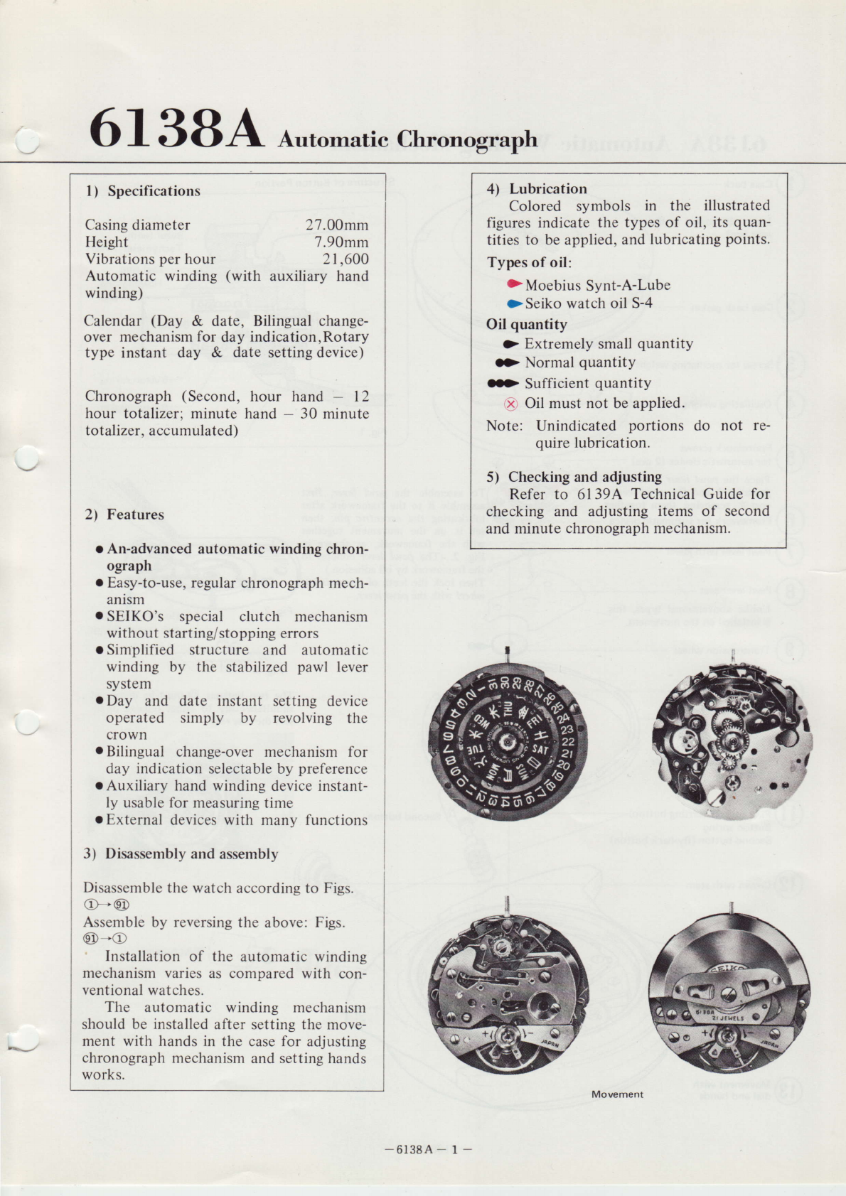
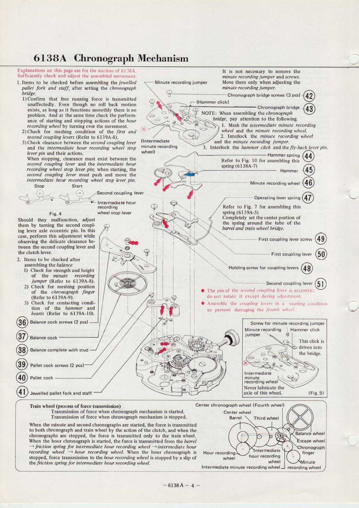
6138A ChronOgraPh Mechanisllfl
Explanationson this page
arefor the nuclcus
of 6138A.
Sufficiently checkand adjust the assernbled
movetnent.
I.Items to be checked before assemblingthe iewelled
pallet fork and staff, after setting the chronograph
bridge.
l) Confirm that free running force is transmitted
unaffectedly. Even though no roll back motion
exists, as long as it functions smoothly there is no
problem. And at the same time check the perform-
ance of starting and stopping actions of the hour
recording wheel by turning over the movement.
2) Check for meshing condition of the first and
secondcoupling /euers
(Refer to 5139A-8).
3) Check clearance between the second coupling lever
and the intermediate hour recording wheel stop
lever pin and their actions.
When stopping, clearance must exist between the
second coupling lever and the intermediate hour
recording wheel stop lever pin; when starting, the
second coupling lever must push and move the
intermediate hour recording wheel stop lever pin.
む
{lntermediate
minute recordin9
wheel}
1. Mesh the intermeditte minute recording
wheel and the minute recording wheel.
Refer to Fig. l0 for assembling this
spring
(6138A-7)
Refer to Fな
.7 foF aSSembling this
spring(6139A‑5)
Stop Start
嗅 χ
二
斐
ζ
iI:‖
∬:l11:"r
缶
recordi ng
wheel stop lever
Fis.4
Should they malfunction, adjust
them by tuming the secondcoupl-
ing lever axle eccentricpin. In this
case,
perform this adjustment
while
observing
the delicateclearance
be-
tween thesecondcoupling
leverand
the clutchlever.
2. Itemsto bechecked
after
assemblingthebalance
l) Checkfor strength
andheight
of the minute recording
iumper (Refer to 6139A-8).
2) Check for meshing position
of the chronograph finger
(Refer
to 6139A.-9).
3) Check for contacting condi-
tion of the hammer and
hearts
(Refer to 61394-10).
Balancecock screws
(2 pcsl
Balance
cock
Balancecomplete with stud
Palletcock screws
(2 pcs)
Palletcock
Jewelled
pallet
fork and staff
\ - Firstcouplingleverscrew
\-- First
couplinglever
Holdlnぃ¨w for co¨eVers①
①①
\
\\
①①①①①①
`
│、
Trainwheel
(process
of forcetransmission)
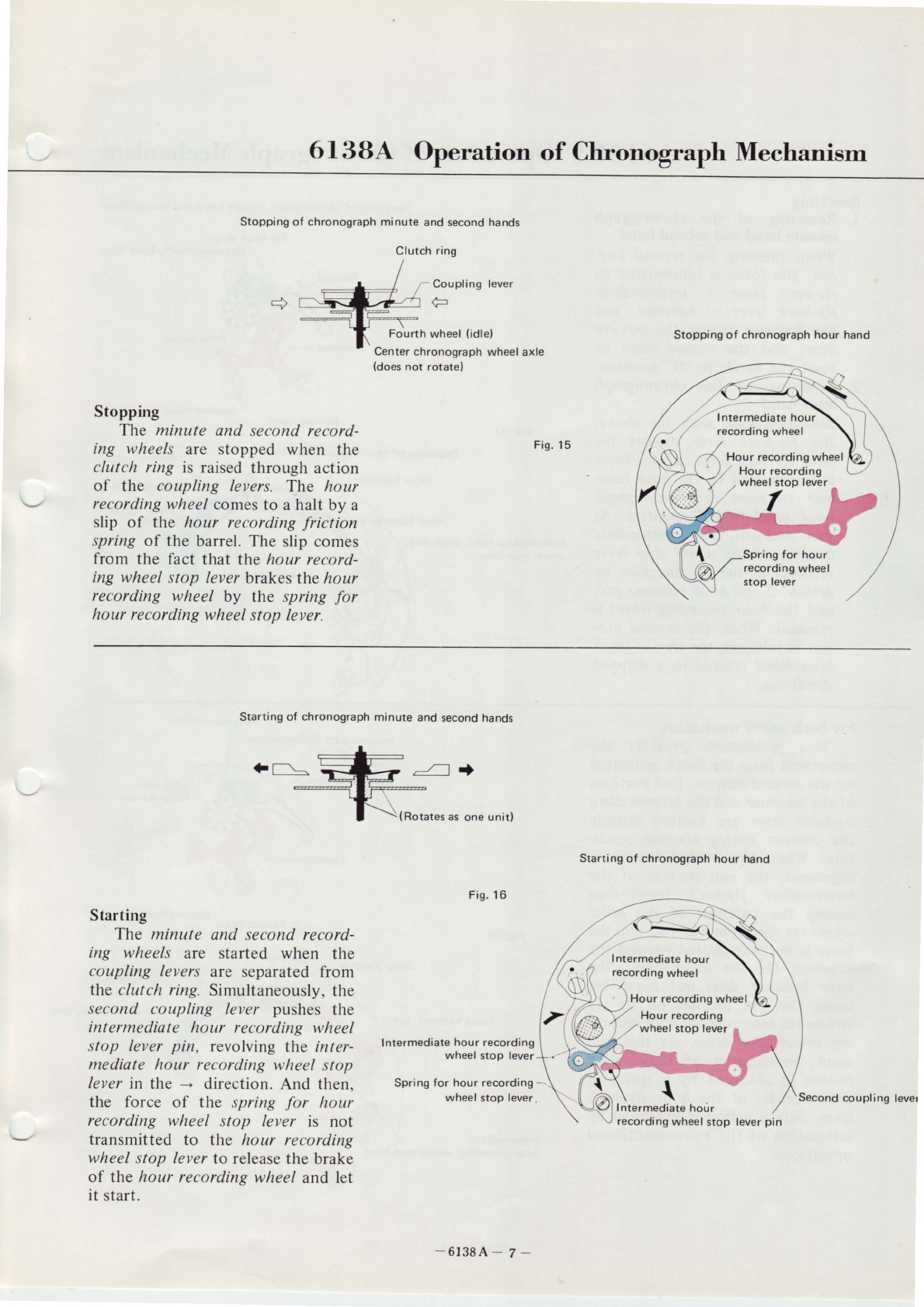
Transmissionof forcewhenchronogtaphmechanismisstarted.
Transmissionofforce whenchrenographmechanismisstopped.
Whentheminute andsecondchronographs
arestarted,theforceistransmitted
to both chronograph
and
train wheelby theactionofthe clutch,andwhenthe
chronographs
are stopped,the force is transmitted only to the train wheel.
Whenthe hour chronographis started,
theforceistransmittedfrcm thebarrel
+ friction sping for intermediatehour recordingwheel+intermediate hour
recording wheel - hour recording wheel. When the hour chronographis Hour
stopped,force transmission
to thehour recordingwheelis stoppedby aslipof
thefriction springfor intermediate hour recording wheel.
It is not necessiuy to remove the
minute recording jumper and,
screws.
g Minute recordingjumper Move them only when adjusting the
\ minute recording iumper.
\ Chronograph bridge screws
(3 pcsl
(Hammer
click) Chronographbridge
NOTE: When assembling the chronogroph
bridge, pay attention to the following.
@④
9
∠『
謂:驚
九賜鰐
耀
Ъ
胤ノ
昭
″力θα
忠躙
静無
①
Hammer ④
―
―
一
―Mttte rec∝
d…J④
―∞
¨mgleverttmgO
Completelysetthe centerportion of
the spring around the tube of the
- barreland train wheelbridge.
\__ A
Second coupting tever (5 l,
O 1hc pinof tlte st'tz-rlld tottltlittg /t'l r/ ir ttttttlrlriv
do rrot rotate it e\ccp1 dtrring rditrstrrtcttt.
e Asserrtblr- lh( (t)uplitlX 1t'tr'r'r iri r \trftitig ri'ntlilt,,r
to prcvert danraging Lltc lrttrrllt vlttli
Centerchronograph
wheel {Fourth wheel)
Center
wheel
Barrel Third wheel
scapewheel
hour recording
wheel
finger
3. Interlock the hammer click andthefly-back leverpin.
Screw
for minuterecording
jumper
Wttrマ
hg
ξTamm∝
引ょ
This click is
dr
en into
1郵
罵
Tiedヾ
L
Neverlubricatethe v
axle
of thiswheel. (Fig.
5)
‑6138A‑4‑
Intermediate
minute recordingwheel recordingwheel

6138A Train Wheel
Lubricating
the pillarwheel
Column
To prevent chipping, install
the pillar wheel on the bor-
rel and train wheel bridge
before assemblinethe latter.
Pillar
wheelscrew
Pillarwheel
Pillarwheelring
(Fly-back
lever)
(Pillar
wheel
jumperl
Assemble the″ rr4″
″力′
′
′to the bガ 確e
wh■ e hterlocking
with the ′r7ar
wheel jumper.
fly-back lever, pillar
second intermediate
and, crown wheel arc
barrel and train wheel
(Operating
lever)
・
⑫①
scr
ew
w
hee
l
w
hee
⁝
a
tc
he
t
e
t R
Ra
tc
h
一
瓦sぉ
"mЫ
eTI芯i「鷲壕
躍
i①
/
(Lubricate
the contacting
surface
of the bridge)
Operating lever,
wheel iumper,
ratchet wheel,
driven into the
bridge.
①
・
①
rew
pcS
SC
に
the condition that the pillar wheelis seton.
O When disassemblingand assemblingthe
bridge, pay attention not to deform the
clutch spring,chronogmphjlnger andthe
Lubricatingthe fourth wheel
Apply oil between the clearance of
the fourth wheel pinion and the axle.
①①
{Frictionspring
for intermediatehour recording
wheel}
(
|ntermediate hour recordin
gwheell
(lntermediate
hour recordingwheel
ring)
呻
―
ギ
竺里
7∫
懲
tけ
attad
①
Center chronograph wheel -
Pay attention to the center
chro nograph wheel whlle handl-
ing it.
d wttdttd画
m①
│ │
│
Escapewheel and pinion-
Complete barrel with arbor
Since the three parts shown in the
following diagramare set on the cover
of thebarrel,these
parts
arenot necessa-
ry to remove
whenreplacingor cleaning
the mainspring.
Dialsideof thebarrel
and trainwheelbridge
(Crown
wheel)
ミ〇〇〇 = ■
‑6138A‑5‑
Fig.7

6138A Hour Chronograph Meehanism
⑫ Cale面
山
e scr帥
颯
3
→
After tightening the calendar plate
screws. check whether or not each
lever operates smoothly by pressing
the portion marked with "O on the
hour fly-back /euer. Causes of mal-
functions are considered to come
from defective assembly
and/or lever
warp when replaced with a new one.
Calendar
plate
Pav attention not to break or bend
thl hour hand axle@when attaching
or detaching the calendar plate.
When assembling the calendar
phte, check on pivoting of the hour
hand axle, and the interlocking con-
dition between the hour wheel and
the intermediate date wheel. If the
hour fly-back /euer protrudes to the
outer circumferential side. lhe calen-
dar phte cannot be assembled.Thus,
wheel
stop lever
l. The hour recording stoP lever
axle is designed
asshownin Fig.
8; when detaching the sPring,
Fig.8 remove
it by slightly
bending
it.
lntermediate
hour
stop lever
2. The hour recording stop lever
spring axle is an eccentric pin.
Do not turn it asit isnot screw.
If it is turnedinadvertentlY,al-
wayscofect it sothat thegroove
of theeccentric
prn (arrowmark)
fac.esthe center of the hour
recording wheel. Correct tt in a
direction that spring force be-
comesstrongasillustrated
left in
recording wheel stop lever
Hour recording
wheel
Θ
tjon around the eccentric pin of the
plate is shown in the following
diagram. Correctly set the eccentric
pin in the grooved portion.
Hour hammer
spring
Hour fly-back lever
Mainplate
Hour fly-back lever
l. Referto Fig. 15in 61384-7
for
the set position of the hour
fly-back lever. The crosssection
diagramis shown in Fig. 10.
Correctlysetit to the eccentric
portion.
2. Do not tum the eccentric
pin of
the hour fly-back lever. lf it is
turned inadvertently,correct it
asshown
inFig.
11.
Fig.11 1 Correct the eccentric
' pin so that the larger
surface of it faces the
secondbutton
::I:Ⅲ
∝
①
Refer to Fig.17h6138A‑8 and V
the fo1lowing diagram for the
set position of the力ο
″力′〃a″
1. Set position of the 力ο
″
力α″″′″αχル
彦趙琥デ
増
彎
¶忠
2. Interlocking with theゴ ″′
ι′
″′グ″′′
力ο′
″ ″′οοr磯″
g"hο ι
′s′ο
ρ′οレ′″
Hour hammeroin Hourhammer Intermediate
hour recording
Plain- Section wheel stop
lever
Fig 13
酔バ
iLlk
① HOur
∞d"Wttd並
¨
リ
④ HOur
∞d"Whee
recording
Pay attention not to scratch
the teeth of the hour re-
cording wfteel when handl-
ing it.
Assemble the intermediate
date wheel with the pinion
positioned upward.
/
≠
≠
/
The hour recording stop
lever spring axle is an
eccentric pin; do not
turn it. If it is turned
inadvertently, adjust it
by referring to Fig. 9.
①h…
赫
劃 O④O
‑6138A‑6‑
Fig 10
(Refer
to Fig.14l
Fi9 14
〇◎8亀〇買
ざ
三
―MШ
"wheel O
―
cannonpinion④
The hour fly-back lever axle is an
eccentric pin; do not turn it. If it is
/ ヽ
turned inadvertently, adJust it by
{Refer to Fi9.10)referrilng to Fig.10.
Centerwheel
wheelbridge
②陥W Wttd一
―Center
wheelbridgescrew

6f 3BA Operation of Chronograph Meehanism
Stopping of chronograph minute and secondhands
Clutch ring
Coupling lever
Fourth wheel (idle)
Centerchronograph wheel axle
(does
not rotatel
Stopping
The minute and second record-
ing wheels are stopped when the Fis'
15
clutch ring is raised through action
of the coupling levers. The hour
recordingwheelcomes
to ahalt by a
slip of the hour recording friction
spring of the barrel. The slip comes
from the fact that the hour record-
ing wheelstop leverbrakes
thehour
recording wheel by the spring for
hour recordingwheel
stop lever.
→
Stopping of chronograph hour hand
Hour recordingwheel
Hour recording
Starting of chronograph minute and secondhands
tf\-
(Rotates
as one unitl
Fis.16
Starting
The minute and second record-
ing wheels are started when the
coupling levers are separatedfrom
the clutch ring. Simultaneously,
the
second coupling lever pushes the
intermediate hour recording wheel
stop lever pin, revolving the inter-
mediate hour recording wheel stop
lever
in the - direction.And then.
the force of the spring for hour
recording wheel stop lever is not
transmitted to the hour recording
wheelstop leverto release
the brake
of the hour recording wheel and let
it start.
Intermediate hour recording
wheel stop lever
Spring for hour recording-
wheel stop lever.
Starting of chronograph hour hand
‑6138A‑7‑
recording wheel stop lever
pin
Second coupling lwer

6f 3BA Operation of Chronograph Meehanism ヽ一
Resetting
1. Resetting of the chronograph
minute hand and secondhand
When pressing the second but-
ton, the force is transmitted'to
fly-back lever - intermediate
fly-back lever - hammer, and
the hammer strikes the minute
heart and the second heart to
reset the handsto "0" position.
2. Resetting of the chronograph
hour hand
Simultaneously with the above,
the fly-back lever presses the
hour fly-back leverandthe force
is transmitted to the hour ham-
mer to reset the chronograph
hour hand to "0" position. At
this moment, the intermediate
hour recording wheel stop lever
revolves in the - direction by
action of the hour hammer pin,
and the hour recording wheel is
released.When the second but-
ton is released,
the chronograph
hour hand returns to a stopped
condition.
Resetting
of chronograph minute hand and secondhand
ntermediate fly-back lever
llar
wheel
Second heart
Fig.17
Intermediate hour
wheel stop lever
′
S∝ °
nd button
Minute heart
Resettingof chronograph hour hand
Hour hammer
Hour hamrneipin
Hour heart
F!y‐
back lever
Hour f
ly-lcack
lever
Fly-back lever
Fly‐back safety mechanisln
This mechanism protects the
movement frorn the shock generated
by the sθθ
ο′ご わ
′′
ο
. End portions
of the力 α
″
7′ηθ″and the′ η′
θ
/″θσ
Jα′
θ
/7y―
bαθた ′
θ
ッ
θ
″
are located outside
the column du ng starting condi―
tion. When the sθ θ
οηご b′′Ott is
depressed, the end portion of the
J′
′
θ
″
θグ
Ji2′
θ
ノノ
‐
わαθた Jθッθ″
slips
among the columns of the ρ
″ια
″
w力θθ′
(as shOWn in Fig.18),and the
force is not translnitted beyond the
力
α
″
ッηθた
On the other hand, the
力
ο
″ 力α
″
2′ηθ″
dOes not move be―
cause the pin located on its tip
strikes the Jκ
′
′
θdiα′θttο
″″
θ
θOrJ―
J″
g″ 力
θ
′s′
ο
ρたソ
θ″.At this mo―
ment, momentum of the sθ εο″ご
b′′0″ is absorbed by a sprihging
chaTacteristic of the ttο
夕″′ン
‐
bαεた
′θ
ν
た
Safety action is exhibited by
integration of thc above‐Inentioned
OperatiOns.
Hour hammer pin
Intermediate
hour recording wheel stop
(Columnl
Pillar
wheel
Fig.18
Hour hammer
\
Second button
.Hour fly-back lever
D
艤\
‑6138A‑8‑

∪613BA Setting Mechanism
Set the setting
wheel lever plate as
drown in the fol-
⑫:∬
i当
蒟ふ2p
①S面
¨
軒
Ⅲ
"
①YokespringO帆
lever sttu
(85) s""ing wheel
lwer complete
The setting wheel lever
complete can be assernbled
evenafter installing the set-
ting kver spring.
Push this portion with
pair of tweezers.
9 ︲鎖
nO wh":!ever goadrm‐
(D
Check on i settan8 actaon and locking
con tion(seCOnd c dc of the ,w″)
a conditaon Of insming the sarr′
磁 θ″ セ略 οο
″た′a Since es″ 姥
磁 ι″ is dゅ tly Taised in this conditioL
perfom checking w
にliBhtly pressing
the″ilrg ttθa
lowing
Setting lever
Setting wheel
lever plate
Setting lwer spring
↑︶趾Setting
lwer
も
bりぬ艤
藝
①
―
一
Daγ
lateC°
rrettrwh
:rocttn9:ever〈
D
│
―・
①①
︲e d
ha
x
w
he
it
h
W
tC
¨
・ ^・
C⁚u
鋼 一
w
"口
品
n①
Ⅷ
山sLm①
し
摯
hg
酬│
r gu"d(D
Lubrlcating
thesatt rg
vulreellqer complqte
‑6138A‑9‑

6f 3BA Setting Mechanism
Ordinary position of crown (main-
springwinding)
The crown wheelandthesecond
intermediate ratchet wheel are
caulked on the barrel and train
wheel bridge. The intermediate rat-
chet wheel is supportedby a pin
mounted
on theplate.
Secondposition of crown (day and
datecorrection)
l. Clockwise- Datecorrection
When turning the crown to the
right (clockwise), the correcting
gear moves to the date dial side
and interlocks
with it. thus date
is corrected.Force transmission
is through crown + clutch
wheel - setting wheel + cor-
recting g€ar + date dial.
2. Counterclockwise - Day correc-
tion
When turning the crown to the
left (counterclockwise), the cor-
recting gear moves to the day
star with dial disk sideand inter-
locks with the intermediate
wheel for day correction, and
day is corrected.Force is trans-
mitted through crlwn - clutclt
wheel - setting wheel + cor-
recting gear + intermediate
wheel for day correction - day
star with dial disk.
Third position of crown (setting
time)
The setting wheel
levercomplete
moves
to the minute wheelsideby
action of the settingleverwith axle,
and the intermediate setting wheel
interlocks with the minute wheel.
hand is setcorrectly.
Simultaneous-
ly, motion of thesettingwheel
lever
complete is transmitted to the day-
date correction wheelrocking lever,
and the cotecting gear attains a
position where it interlocks neither
the date dial norintermediatewheel
for day correction by action of the
setting wheellevercomplete andthe
day-date correction wheel rocking
lever.
Crown wheel
Winding
pinion
Intermediate ratchet
wheel
Second intermediate
ratchet wheel
Ratchet wheel (barrell
Fis.21
―
Date dial
Fis.22
(Day
starl
Intern
for da
Fis.23
Minute wheel
(
Intermediate settingwheel)
Setting wheel lever
complete
Daydate corrector
wheel rocking lever
Fi9.24
-6138A - l0-
Intermediate wheel
for day correction
Table of contents
Other Seiko Watch manuals

Seiko
Seiko 4F Series Use and care manual

Seiko
Seiko 5Y89 User manual

Seiko
Seiko 6R20A Installer manual

Seiko
Seiko 4F32 User manual

Seiko
Seiko 4F32 User manual

Seiko
Seiko SRWZ24 User manual

Seiko
Seiko 5Y85A Quick start guide

Seiko
Seiko 5M84A User manual

Seiko
Seiko Prospex SNE585P User manual

Seiko
Seiko RC-4000 User manual

Seiko
Seiko G300 User manual

Seiko
Seiko VD 52 B User manual

Seiko
Seiko 6R15 User manual

Seiko
Seiko 7C46 User manual

Seiko
Seiko 7B72 Operating manual

Seiko
Seiko Presage SRE010J User manual

Seiko
Seiko 5M63 User manual

Seiko
Seiko 2A27 User manual

Seiko
Seiko 8X53 Series User manual

Seiko
Seiko SSB261P1 User manual