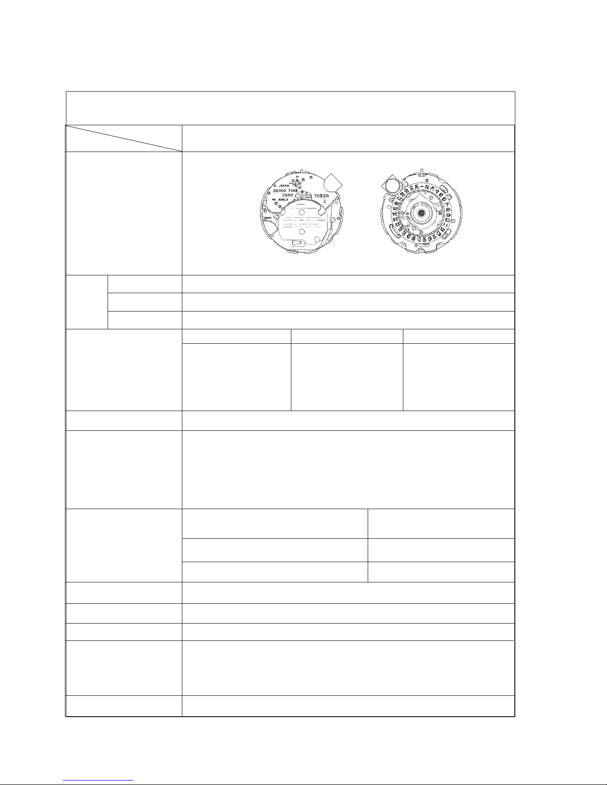
Cal. 7K52A
10
TECHNICAL GUIDE
III. REMARKS ON DISASSEMBLING AND REASSEMBLING
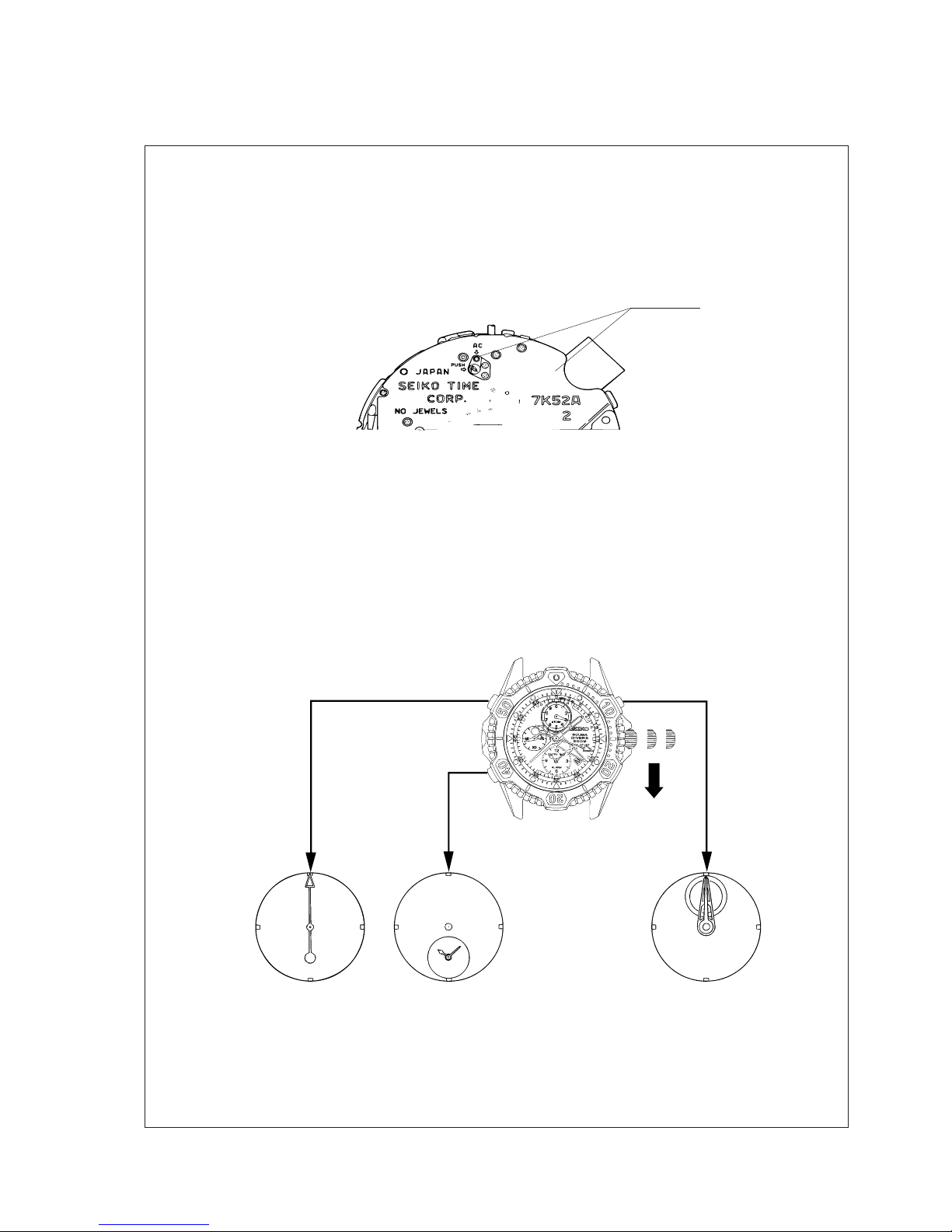
The switch lead terminal is
slipped into the gap under the
auto switch terminal.
<Improper contact>
<Proper contact>
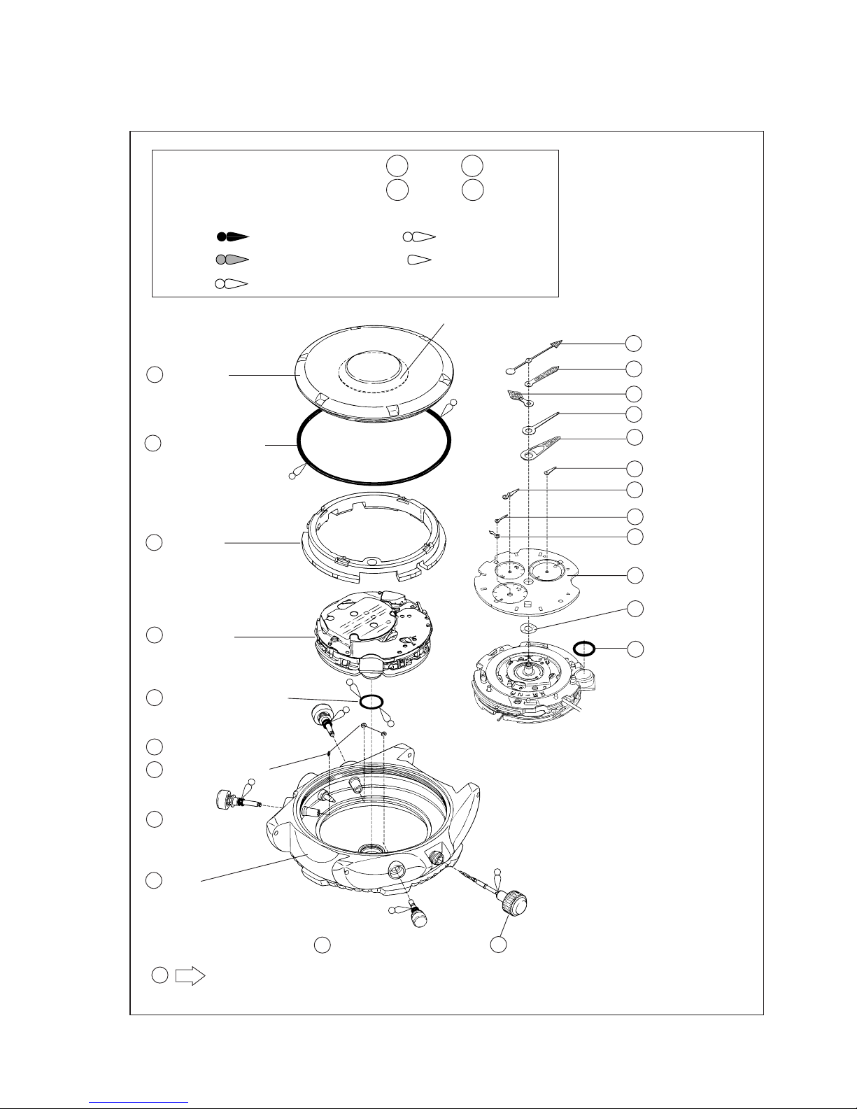
5 Movement
When installing the movement into the case, check that the switch lead terminal (A) securely makes contact
with the auto switch terminal of the case.
Note :
Be sure to observe the following to prevent any difference of indication between the depth and
maximum depth hands.
• After pressing the button at the 2 o’clock side in step "4" above, be careful not to give the watch any
vibration or impact until you finish installing the maximum depth hand.
• Push in the hands straight from above, taking care not to turn them.
*After installing the hands, recall the log data to check that :
• there is no difference of indication between the depth and the maximum depth hands.
• when the depth hand returns to indicate the average depth, the maximum depth hand stays where it
was advanced by the depth hand.
Switch lead terminal (A) Auto switch terminal
15 Maximum depth hand
17 1/10 m depth hand
16 Depth hand
10
1/10 m depth hand
Depth hand
Maximum depth
hand
• Remarks on installing
• When installing the hands for diving measurement, check
that they accurately point to the diving measurement
scales on the dial.
• The depth hand moves correspondingly with the 1/10 m
depth hand, and the maximum depth hand is advanced by
the depth hand. To install them, therefore, be sure to
follow the procedure below.
1) Reset the circuit.
2) Pull out the crown to the second click and wait for more
than 40 seconds until all the wheels on the train wheel
bridge stop moving.
3) Reset the 1/10 m depth and depth hands to “0” posi-
tion as shown in the illustration at upper right.
4) After pressing the button at the 2 o’clock side more
than 15 times, put the maximum depth hand exactly
onto the depth hand as shown in the illustration at right.