Seiler 935 LED User manual

OWNER’S MANUAL
PRECISION MICROSCOPES
COLPOSCOPE
MODEL 935 LED

2
Register your product warranty online:
http://www.seilermicro.com/warranty-registration/

3
TABLE OF CONTENTS
INDICATIONS FOR USE 4
PRESENTATION AND USE 4
COLPOSCOPE FLOOR STAND 4
THE COLPOSCOPE HEAD 5
CLEANING 5
HOW TO FOCUS THE COLPOSCOPE 6
OPTICAL AND FIELD MAGNIFICATION TABLE 7
TECHNICAL DATA 7
LED LIGHTSOURCE 8
OWNER’S RECORD 14
NOTES 14

4
INDICATIONS FOR USE
PRESENTATION AND USE
COLPOSCOPE FLOOR STAND
The Seiler Colposcope is intended to provide magnified visualization of the tissues of the vulva, vagina, cervix, and ano-
genital area. It is used to evaluate these tissues, select areas for biopsy, as necessary, and to facilitate related proce-
dures, e.g., LEEP, conization, etc.
Caution: Federal law restricts this device to sale by or on the order of a physician or practitioner trained in its use.
The sections contained in this Manual were especially grouped to serve the owners of the COLPOSCOPE MODEL 935
from Seiler Precision Microscopes.
Read this Manual before setting up the equipment, in order to avoid damage from improper usage.
For safe use of the colposcope, it is necessary to be familiar with the details of its operation prior to use.
Therefore, it is advisable that personnel operating the colposcope read this manual prior to using the equipment.
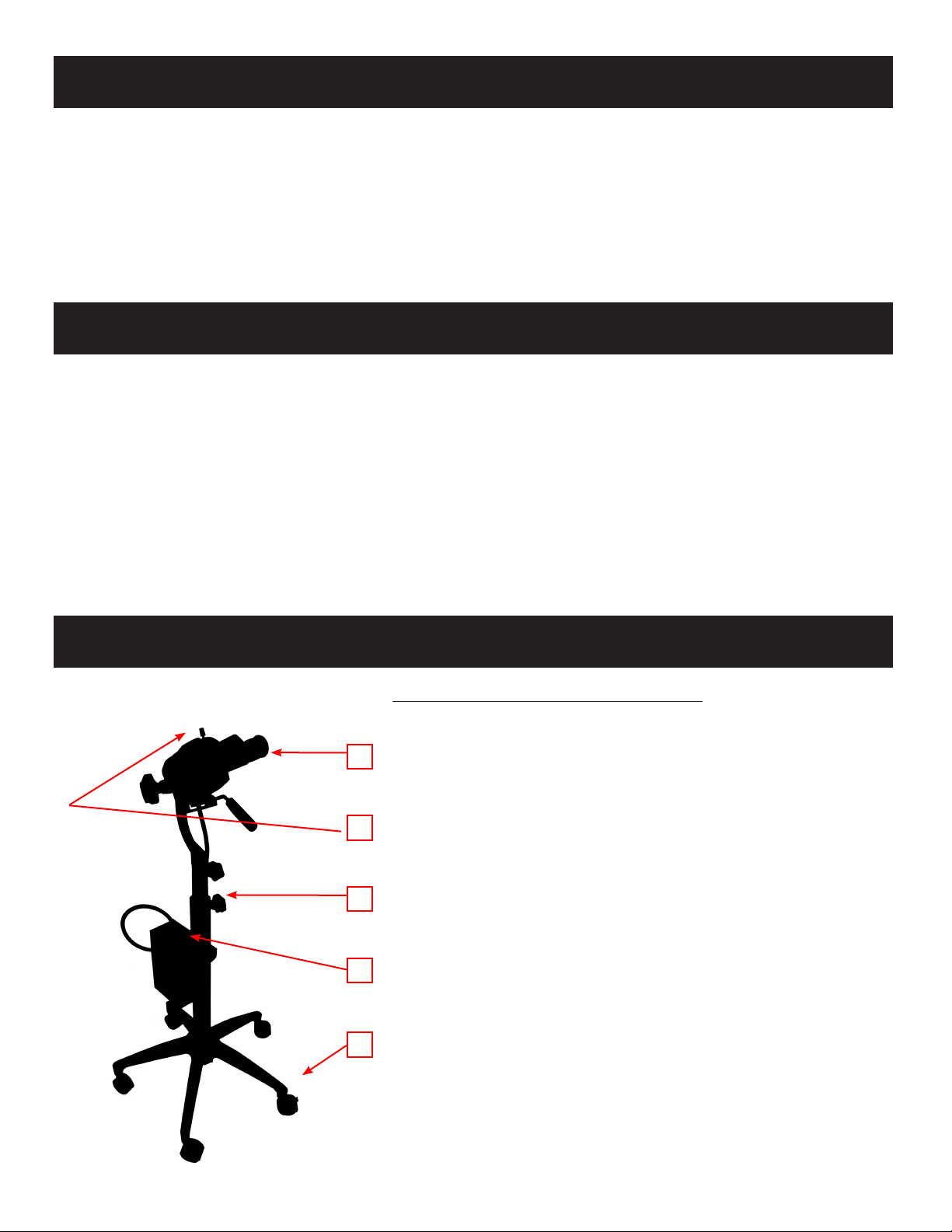
NOMENCLATURE OF THE NUMBERED PARTS
1) Colposcope Head
2) Head securing knob (Caution: Optics will drop when knob is loosened.)
3) Column height adjusting knob
4) LED Illuminator
5) Base with casters
A knob located at the stand tube (item 3) fixes the vertical movement of
the column.
By turning the knob (item 3) counterclockwise or clockwise, the system
can be released or fixed, and the height of the column be adjusted to
achieve the correct height for the patient examination.
1
2
3
4
5

5
THE COLPOSCOPE HEAD
CLEANING
OPTIC POD COMPONENTS
Eyepieces Binocular Head
Thumb Screw
Magnicaon Turret
Objecve Lens
Fine Focus Knob
Green Filter (Push/Pull Knob)
Handle
Tension Adjustment Knob
The Objective, at the bottom of the Colposcope body, may be exposed to blood and other bodily fluids. Spots on the objective
dim the passage of light.
Alcohol or warm water in a mild detergent, applied with a clean cotton swab can be used to remove all smudges. Apply with
soft and CIRCULAR movements. Follow your laboratory’s procedures to remove bloodstains or other contaminants from your
equipment.
If the objective is too blotched, change to another cotton swab for each circular movement to avoid spreading the impurities
again.
The Objective lens can be protected by use of the Sterilizable Protector Cap. It is fitted on the external diameter of the objec-
tive lens and protects it against mechanical damage and against contamination. (catalog #6132000)
Clean the metallic parts (chrome-plated or painted) with cotton, alcohol or mild detergent.
Lubrication
It is recommended to lubricate the Colposcope head after 5 years of use.

6
HOW TO FOCUS THE COLPOSCOPE
Preliminarily:
Displace the Articulated Arm of the stand set where the colposcope is fixed, and point its objective to the direction of the field
to be observed. Note that the objective, at front of the Colposcope, be positioned at a distance equal the focus engraved in
millimeters on the external face of the objective. Example: With a 300mm objective, keep a distance of about 300mm between
the objective and the specimen.
Focus the observation field
Interpupillary distance adjustment:: Look through the two eyepieces with both eyes open and adjust the interpupillary distance
as explained below in the items “inclined binoculars” and “straight binoculars”, until they are juxtaposed to the two pupils and
the vision of the field appears as only one image.
With the inclined binoculars grasp each tube of the of the binoculars and move the tubes in or out, so that, as it was already
said, the eyepieces are juxtaposed to the observer’s pupils.
With the straight binoculars the action of separation or approach is made in a soft and semi-rotation movement, in both of the
prism boxes.
You should now, using both eyes, see one clear stereoscopic image.
Parfocalizing Procedure:
1) Set both eyepieces at zero (0).
2) Turn the magnification drum to the highest setting and focus sharply on a target, such as a piece of paper with an “X”
drawn on it, by using the focusing knobs.
3) Then turn the magnification drum to the lowest setting (1) and focus by turning the eyepieces clockwise or counter clock-
wise until you reach sharp focus.
4) Once the image is clear in both eyes, the Parfocalizing Process is complete.

7
OPTICAL AND FIELD MAGNIFICATION TABLE
TECHNICAL DATA
The optical magnifications achieved with the Colposcope are determined by 3 variables: the objective focal distance,
the position of the Magnification Selector, and by the eyepiece used.
The table shows the optical magnification and the observed field diameters, in millimeters, depending on those vari-
ables. At the bottom line of the table the illuminated field is shown, corresponding to the light disk incident on the
field, with a diameter that depends only on the focus of the work objective.
The magnification selector has 3 positions: 1, 2, and 3. The 2nd position is repeated in the selector. The working posi-
tion is the one aligned to the black dot mark.
A - Colposcope Head
Microscope Galilean System
Binoculars Straight, F=170mm (optional: Inclined, F=135)
Objective 300mm (optional: 200-400mm)
Eyepieces WF 12.5x (optional: 10x/18x)
Magnification Refer to Table
Interpupillary Distance Adjustable between 42mm & 75mm
Illumination LED Illumination Sytem
(Optional: Halogen 15V/150W or Metal Halide)
Light Conductor Liquid Light Guide
Filter Green
Focusing Fine Focus: 11mm
B - Colposcope Stand
Angular Rotation 360 Degrees
Distance between the 1016mm-1193mm
floor and the objective
Base Five casters, two with brakes
Total Weight 18.14 kg
BINOCULAR HEAD FOCAL LENGTH = 170
MGNIFICATION FIELD MGNIFICATION FIELD MGNIFICATION FIELD MGNIFICATION FIELD MGNIFICATION FIELD
1(0.6) 5.83 30.88 5.10 35.29 4.08 44.12 3.40 52.94 2.55 70.59
2(1.0) 9.71 18.53 8.50 21.18 6.80 26.47 5.67 31.76 4.25 42.35
3(1.6) 15.54 11.58 13.60 13.24 10.88 16.54 9.07 19.85 6.80 26.47
1(0.6) 7.29 27.45 6.38 31.37 5.10 39.22 4.25 47.06 3.19 62.75
2(1.0) 12.14 16.47 10.63 18.82 8.50 23.53 7.08 28.24 5.31 37.65
3(1.6) 19.43 10.29 17.00 11.76 13.60 14.71 11.33 17.65 8.50 23.53
1(0.6) 9.33 27.45 8.16 31.37 6.53 39.22 5.44 47.06 4.08 62.75
2(1.0) 15.54 16.47 13.60 18.82 10.88 23.53 9.07 28.24 6.80 37.65
3(1.6) 24.87 10.29 21.76 11.76 17.41 14.71 14.51 17.65 10.88 23.53
2(0.6) 11.66 20.59 10.20 23.53 8.16 29.41 6.80 35.29 5.10 47.06
3(1.0) 19.43 12.35 17.00 14.12 13.60 17.65 11.33 21.18 8.50 28.24
4(1.6) 31.09 7.72 27.20 8.82 21.76 11.03 18.13 13.24 13.60 17.65
illuminated field
65
EYEPIECE
POSITION OF
BUTTON
OBJECTIVE LENSES
175
200
MAGNIFICATION TABLE FOR 935.
10x/18
12.5x/16
16x/16
20x/12
250
300
400
72
90
108
144

8
LED LIGHTSOURCE
1. INTRODUCTION
Congratulaons on the purchase of your new SSL-2000 Light Source! This user-friendly LED light source is a high
eciency light source ulizing state of-the-art superior illuminaon technology. It oers a variety of features such as:
• 6500º K daylight brightness for good color denion
• Quiet operaon
• Long life, 50,000 hrs.
• Compact and light weight
• Pulse-width Modulaon (PWM) Electrical Dimming
This secon of the manual will help you to install the device and opmally integrate it with other components of
your system. It will also instruct you how to operate the LED Light Source and how to keep it clean. It will give you
maintenance and service guidelines as well as recommendaons for best performance results.
1.1 INDICATIONS FOR USE: The LED Light Source is used to illuminate the site of surgery during minimally invasive
surgical procedures. The light is transmied from the light source through a ber opc cable and a scope.
2. WARNINGS
To prevent re or electric shock, do not open or expose the LED light source unit to rain or moisture. Refer all servicing to
qualied personnel only.
Not suitable for use in presence of ammable anesthec mixture with air or with oxygen or nitrate oxide.
To prevent any potenal electro-magnec interference, do not use any kind of cellular phone near the
light source.
This product should be used only with type BF endoscopic instruments which have been cered
according to IEC 601-1 for medical equipment and IEC 601-2-18 for endoscopic equipment.
Cauon: This product is not provided as sterile.
Cauon: All devices connecng to the LED Light Source must be classied as medical equipment. When
addional informaon processing equipment is connected to the LED Light Source, the operator must
determine that all equipment complies with the appropriate end-product standards (such as IEC 60950
or IEC 60065 and the Standard for Medical System, IEC 60601-1-1).
Cauon: The LED Light source can cause permanent eye damage if viewed directly with unprotected eye.
To reduce the chance of eye damage, set the intensity control always to the minimum level and plug the
ber opc cable into the unit before turning on the power.
EQUIPMENT CONNECTION
Cauon: The ber opc cable must be a NON-CONDUCTIVE CABLE. It should not have conducve
shielding or any other conducve connecon between the paent and equipment. Such connecon will
impair safety of the equipment. It must be rinsed free of soaking/disinfectant soluon and dried before
plugging into the LED light source receptacle. Ensure the opcal surface is clean before engaging into the
light source.

9
3. SPECIFICATIONS
Item Specicaon
Light Source Type LED (Light Eming Diode)
Power 50 Wa
Color Temperature 6500ºK
Led life 50,000 hours (typical)
Light guide adapter
Brightness control PWM (Pulse-width Modulaon) – 0-100% Dimming
Input voltage 100-240V AC, 50/60 Hz
Rated Power 52 wa
Regulatory Approvals UL60601-1,CAN/CSA C22.2 No.601.1 (SUP1+AM2),EN 60601-1-2 and CE
marked
Equipment Class Class I, BF-type
Mode of Operaon Connuous operaon
Water Resistant Not Protected Equipment, IPX0
Operang Environment
Temperature
Relave Humidity
Air Pressure
+0° to +40° C (32° to 104° F)
0 to 85%rh, non condensing
700 to 1060 hPa
Storage Environment
Temperature
Relave Humidity
Air Pressure
-20° to +60° C (-4° to 140° F)
30 to 95%rh, non condensing
700 to 1060 hPa
Dimensions 4.65” W x 3.32” H x 7.25” D
Weight 2.5 lbs./1.14 kg
4. OPERATING ELEMENTS, SYMBOLS AND FUNCTIONS
4.1 FRONT PANEL
No. Name Funcon
1 Power switch Turns the light source on and o. Fan will operate
2 Light Guide Adapter
3 Intensity Control Electronically controls the light output
2
1
3

10
4.2 REAR PANEL
Figure 2. LED Light Source Rear Panel
No. Name Funcon
1 AC main inlet Accepts AC power cord
2 Fuse 2A, 250V (1/4” x 1 ¼”) me delay
3 Grounding Connector For potenal equalizaon
4Venng grids Allows adequate venlaon and cooling of the light source
4.3 Boom Panel
Figure 3. LED Light Source Product Label
2
3
14

11
5. INSTALLATION
5.1 SETTING UP THE LED LIGHT SOURCE
Place the LED light source on a stable surface (cart, counter, stand, etc.).
NOTE: Avoid places where the light source may be splashed with liquid.
Absolutely DO NOT use in any environment with explosive or ammable gases.
DO NOT block the venng grids of the LED light source.
Make sure the power switch is in OFF posion.
Connect AC power cord to the power inlet located on the rear panel of the light source.
CAUTION: Use only cords provided with the light source.
Plug the AC power cord into a wall outlet using the three-prong plug supplied with the unit.
CAUTION: To prevent electric shock, connect power cords of peripheral equipment through medical isolaon
transformers.
NOTE: When using medical isolaon transformer, be sure to check the transformer power rangs.
Make sure that the power cord is connected to the main power with three-prong plug (USA use UL2601-1 rated
isolaon transformers and/or power strips only).
CAUTION: When used in clinical or residenal areas near radio or TV units, this equipment may be subjected to radio
interference. To avoid adverse electromagnec eects, DO NOT operate this equipment near RF energy equipment.
5.2 CONNECTING THE FIBER OPTIC CABLE
Turn intensity control to the minimum seng. Connect the light cable to the instrument and then plug the light cable
endng into the port on the front panel.
6. OPERATION
6.1 POWERING UP THE LED LIGHT SOURCE
To operate the LED light source: Turn on the power switch. The indicator on power switch will light.
6.2 LIGHT BRIGHTNESS DISPLAY AND CONTROL
The light brightness adjustment enables the user to obtain a brighter or darker illuminaon of the object of observaon.
Adjust the light intensity by turning the intensity control knob.
7. CLEANING
NOTE: Always disconnect the power cord before cleaning the system.
The unit can be cleaned with any cleaning agent, which is used for external cleaning of electric equipment, according to
instrucons given by the manufacturer of the cleaning soluon.
Do not allow excessive moisture or liquids to come in direct contact with the unit.
Do not use cleaning agents that are not permied for use with plascs, i.e., ammonia, acetone, salty acids (HCl), etc.
Do not allow cleaning agents or liquids to enter the unit outlets.

12
8. DISINFECTION
8.1 DISINFECTING THE UNIT
NOTE: Always disconnect the power cord before cleaning the system.
Use any disinfectant agents which are commonly applied while disinfecng surfaces of electric medical equipment. Such
disinfectant agents are usually in the form of sprays or damp cloths.
Follow the instrucons given by the manufacturer of the disinfectant soluon.
9. SERVICING AND REPAIR
Defecve items of equipment are to be serviced and repaired exclusively by persons authorized by the manufacturer. All
repair work shall employ original manufacturer’s parts only.
9.1 FUSE REPLACEMENT
CAUTION: Always disconnect power cord and turn main switch o before fuse replacement.
Turn light source o and unplug power cord. On back of unit remove fuse by turning fuse cover and pulling out fuse.
Replace fuse with 2 AMP (1/4” x 1 ¼”) me delay 250V rated fuse. Insert back into fuse housing.
Re-connect the power cord and turn the LED light source on according to secon 6.1.
9.2 LIMITED WARRANTY
Your LED light source carries a 1-year warranty from the date of shipment on workmanship and all defects of materi-
al, excluding replaceable sweatbands, headband, beropc cable and lamps. Should your product prove to have such
defects within one year of the shipment. Seiler Instrument will repair or replace the product or component part without
charge. Should your LED Light Source product(s) need servicing under this warranty, please contact, Seiler Instrument
return authorizaon documentaon. You should carefully pack unit in a sturdy carton and ship it to the factory. Please
include a note describing the defects, your name, telephone number and a return address. Warranty does not cover
equipment subject to misuse, accidental damage, normal wear and tear or if transferred to a new owner without autho-
rizaon from Seiler Instrument. This warranty gives you specic legal rights and you may also have other rights that vary
from state to state.
POST WARRANTY REPAIRS: You may return your product(s) for repair, shipping prepaid to the factory. Your product will
be inspected and an esmate of repair charges will be submied to you for approval. Payment must be received before
repairs are completed.
• In the US: 800-489-2282 (toll free)
• FAX number: 314-968-3601
• Customer Service: 314-218-6336

13
10. END OF PRODUCT LIFE
We encourage our customers to recycle this product whenever possible. Disposal of this unit must be performed in ac-
cordance with the applicable local environmental regulaons.
In the United States a list of recyclers in your area can be found at: hp:/www.eiae.org/.
Please contact customer service to issue a return authorizaon to return product to manufacturer at the end of product
life.
11. TROUBLESHOOTING
Problem Soluon
The power indicator (refer to 4.1)
is not lit.
A. Check that the AC power cord is properly connected.
B. Check the unit fuses. If necessary, replace.
The power indicator is lit, but the
lamp will not ignite.
Turn intensity control know clockwise to increase light output intensity.

14
Model Number
Serial Number
Date Purchased
Locaon Purchased
OWNER’S RECORD
NOTES

15
We are here to serve you!
If you have any questions regarding Seiler’s products or services,
please feel free to contact us.
Toll-Free: 800.489.2282
Local: 314.968.2282
Fax: 314.968.3601
www.seilerinst.com
• Microscope Division Manager
Dane Carlson
• Corporate Marketing/Sales Representative
Nicole Rasch
• Technical Product Information
Tony Leise
• Bulb Order Information
Sandra Jeremich
PRECISION MICROSCOPES

PRECISION MICROSCOPES
3433 Tree Court Industrial Blvd.
St. Louis, Missouri 63122
Toll Free: (800) 489-2282
Local: (314) 968-2282
Email: [email protected]
Web: www.seilerinst.com
Version 09/22/14
Table of contents
Other Seiler Medical Equipment manuals
Popular Medical Equipment manuals by other brands

Braun
Braun Oral-B Plak Control MD 9000 use instructions

Chattanooga
Chattanooga Fluidotherapy Series user manual

ProMed
ProMed ProM-500 instruction manual

SeilerScope
SeilerScope 935 owner's manual

Whitehall
Whitehall Thermalator T-8-S Instructions for operation and care

Virtuox
Virtuox VPOD-H Operator's manual

Medix Biochemica
Medix Biochemica Actim PROM 1ngeni Instructions for use

Sunset Healthcare
Sunset Healthcare ZOEY instruction manual

Enabling Technologies
Enabling Technologies Dynamique Biski owner's manual

Teleflex
Teleflex LMA Supreme Instructions for use

Merck
Merck WHISPER ON ARRIVAL user manual

UroSystem
UroSystem UroDapter user manual