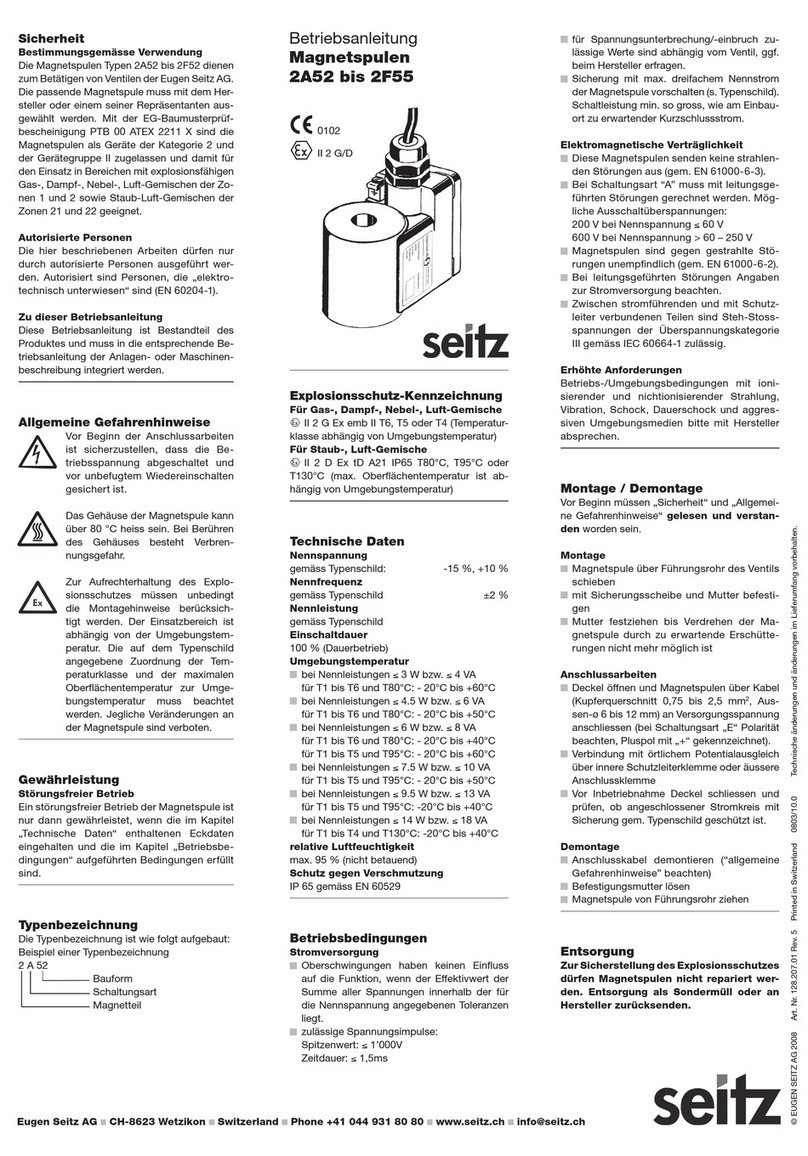
Seitz 2A6 Series User manual

Technische Daten
Nennspannung
gemäss Typenschild -15 %, +10 %
Nennfrequenz
gemäss Typenschild ±2 %
Nennleistung
gemäss Typenschild
Einschaltdauer
100 % (Dauerbetrieb)
Umgebungstemperatur
für T1 bis T6 bzw. T80°C: -50°C bis +40°C
für T1 bis T5 bzw. T95°C: -50°C bis +55°C
für T1 bis T4 bzw. T130°C: -50°C bis +90°C
relative Luftfeuchtigkeit
max. 95 % (nicht betauend)
Schutz gegen Verschmutzung
IP 65/67 gemäss EN 60529
Betriebsbedingungen
Stromversorgung
Oberschwingungen haben keinen Einfluss
auf die Funktion, wenn der Effektivwert der
Summe aller Spannungen innerhalb der für
die Nennspannung angegebenen Toleranzen
liegt.
zulässige Spannungsimpulse:
Spitzenwert: ≤1’000V
Zeitdauer: ≤1,5ms
für Spannungsunterbrechung/-einbruch zu-
lässige Werte sind abhängig vom Ventil (ev.
bei Hersteller erfragen).
Sicherung mit max. dreifachem Nennstrom
der Magnetspule vorschalten. Schaltleistung
min. so gross, wie am Einbauort zu erwarten-
der Kurzschlussstrom.
Elektromagnetische Verträglichkeit
diese Magnetspulen senden keine strahlen-
den Störungen aus (gem. EN 61000-6-3).
bei Schaltungsart “A” muss mit leitungsge-
führten Störungen gerechnet werden. Mögli-
che Ausschaltüberspannungen:
200 V bei Nennspannung ≤60 V
600 V bei Nennspannung > 60 – 250 V
1000 V bei Nennspannung > 250 - 400 V
Magnetspulen sind gegen gestrahlte Störun-
gen unempfindlich (gemäss EN 61000-6-2).
bei leitungsgeführten Störungen Angaben zur
Stromversorgung beachten.
zwischen stromführenden und mit Schutz-
leiter verbundenen Teilen sind Steh-Stoss-
spannungen der Überspannungskategorie III
gemäss IEC 60664-1 zulässig.
Erhöhte Anforderungen
Einsätze bei erhöhten Anforderungen durch
ionisierende und nichtionisierende Strahlung,
Vibration, Schock, Dauerschock und aggres-
sive Umgebungsmedien mit dem Hersteller
absprechen.
Montage / Demontage
Vor Beginn müssen „Sicherheit“ und „Allgemei-
ne Gefahrenhinweise“ gelesen und verstan-
den worden sein.
Montage
Magnetspule über Führungsrohr des Ventils
schieben
mit Sicherungsscheibe und Mutter befestigen
Mutter festziehen bis Verdrehen der Mag-
netspule durch zu erwartende Erschütterun-
gen nicht mehr möglich ist (Drehmoment 15
bis 20 Nm)
Anschlussarbeiten
Magnetspule über Kabel- und Leitungsein-
führungen oder an Rohrleitungssysteme
anschliessen, die den Anforderungen EN
60079-1 entsprechen und für die eine eigene
Prüfbescheinigung vorliegt. Keine Verwen-
dung von Kabel- und Leitungseinführun-
gen ohne Ex-d-/Ex-t-Prüfbescheinigung!
Deckel öffnen (6kt-Schlüssel 17 mm)
Magnetspulen mit Kabel, Kupferquerschnitt
0,75 – 1,5 mm2an Versorgungsspannung
anschliessen.Bei Schaltungsart «E» Polarität
beachten (Pluspol mit «+» gekennzeichnet)
Bei Umgebungstemperaturen ≥50°C, Erwär-
mung von 20 K an Kabeleinführungsstelle be-
rücksichtigen
Verbindung mit örtlichem Potentialausgleich
über innere Schutzleiterklemme oder äussere
Anschlussklemme
Vor Inbetriebnahme Deckel mit 6kt-Schlüssel
bis Anschlag anziehen
Deckel zurückdrehen bis Gewindestift über
nächstliegendem Arretierungsloch platzierbar
Gewindestift mit 6kt-Schlüssel (2 mm) fest-
schrauben
Demontage
Anschlusskabel demontieren («allgemeine
Gefahrenhinweise» beachten)
Befestigungsmutter lösen
Magnetspule von Führungsrohr ziehen
Entsorgung
Zur Sicherstellung des Explosionsschut-
zes dürfen Magnetspulen nicht repariert
werden. Entsorgung als Alteisen oder an
Hersteller zurücksenden.
Betriebsanleitung
Magnetspulen
2A6x, 2C6x, 2E6x, 2F6x
© EUGEN SEITZ AG 2014 Art. Nr. 128.204.01 Rev. 06 Printed in Switzerland 1404/2.0 Technische änderungen und änderungen im Lieferumfang vorbehalten.
Sicherheit
Bestimmungsgemässe Verwendung
Magnetspulen der Typen 2A6x, 2C6x, 2E6x
und 2F6x dienen zur Betätigung von Ventilen
der Eugen Seitz AG. Der zum Ventil passen-
de Typ muss mit dem Hersteller oder seinem
Repräsentanten ausgewählt werden. Die Mag-
netspulen sind mit EG-Baumusterprüfbeschei-
nigung BVS 14 ATEX E011 als Geräte der Grup-
pe II und der Kategorie 2 zugelassen und damit
für den Einsatz in Bereichen mit explosionsfä-
higen Gas-, Dampf-, Nebel-, Luft-Gemischen
der Zonen 1 und 2 sowie Staub-Luft-Gemi-
schen der Zonen 21 und 22 geeignet.
Autorisierte Personen
Die hier beschriebenen Arbeiten dürfen nur
durch autorisierte Personen ausgeführt werden.
Autorisiert sind Personen, die «elektrotechnisch
unterwiesen» sind (EN 60204-1).
Zu dieser Betriebsanleitung
Diese Betriebsanleitung ist Bestandteil des
Produktes und ist in die entsprechenden Be-
triebsanleitungen der Anlagen- oder Maschi-
nenbeschreibungen zu integrieren.
Allgemeine Gefahrenhinweise
Um den Explosionsschutz der Magnetspule
zu gewährleisten, sind jegliche Veränderungen
verboten.
Vor Beginn der Anschlussarbeiten
und der Demontage ist sicherzu-
stellen, dass die Betriebsspannung
abgeschaltet und vor unbefugtem
Wiedereinschalten gesichert ist.
Magnetspulengehäuse kann über
80°C heiss werden.
Verbrennungsgefahr!
Zur Wahrung des Explosionsschut-
zes unbedingt Montagehinweise
beachten! Einsatzbereich ist abhän-
gig von Umgebungstemperatur. Auf
Typenschild angegebene Tempera-
turklassen-Zuordnung zur Umge-
bungstemperatur beachten.
Gewährleistung
Störungsfreier Betrieb
Ein störungsfreier Betrieb ist gewährleistet,
wenn «Technische Daten» und «Betriebsbedin-
gungen» eingehalten werden..
Typenbezeichnung
Beispiel einer Typenbezeichnung
2 A 65
Bauform (je nach Kabel-
einführungsgewinde)
65 = NPT 1/2
67 = M 20x1,5
Schaltungsart
Magnetteil
Explosionsschutz-Kennzeichnung
II 2 G Ex db IIC T6, T5 oder T4
II 2 D Ex tb IIIC T80°C, T95°C oder T130°C
Die Magnetspulen sind konform mit folgenden
Normen: EN 60079-0:2012, EN 60079-1:2007
und EN 60079-31:2009
II 2 G/D
1258
DE /GB/ES/FR/IT/RU

© EUGEN SEITZ AG 2014 Art. Nr. 128.204.01 Rev. 06 Printed in Switzerland 1404/2.0 Subject of technical changes and changes in the scope of delivery.
Technical Data
Rated voltage
According to name plate -15 %, +10 %
Rated frequency
According to name plate ± 2 %
Rated power
According to name plate
Operating time
100 % (continuous duty)
Ambient temperature
For T1 to T6 and T80°C: -50°C to +40°C
For T1 to T5 and T95°C: -50°C to +55°C
For T1 to T4 and T130°C: -50°C to +90°C
Relative humidity
Max. 95% (non-condensing)
Protection against soiling
IP 65/67 according to EN 60529
Operating Conditions
Power supply
Harmonic oscillations have no effect on the
functioning of the device if the r.m.s. value of
the sum of all the voltages lies within the tol-
erances specified for the rated voltage.
Permissible voltage impulses
Peak value ≤1000 V
Duration ≤1.5 ms
The permissible values for voltage interrup-
tions or loss depend on the valve (if necessary,
these can be obtained from the manufacturer).
The device must be protected for up to
three times the rated current of the solenoid.
Breaking capacity at least as great as the
short circuit current to be expected at the
place of installation.
Electromagnetic compatibility:
These solenoids do not emit any radiated dis-
turbances (according to EN 61000-6-3).
Conducted disturbances are to be expected
in the case of circuit type «A».
Possible transient switching voltage:
200 V for a rated voltage ≤60 V
600 V for a rated voltage > 60 – 250 V
1000 V for a rated voltage > 250 – 400 V
Solenoids are not sensitive to radiated
disturbances (according to EN 61000-6-2).
For conducted disturbances consult the
specifications for the power supply.
Surge voltages of over-voltage category III
according to IEC 60664-1 are permissible be-
tween the current-conducting parts and parts
connected to the protective conductor.
Extreme demands
Please consult manufacturer in connection
with using the solenoid under extreme condi-
tions such as ionising and non-ionising radi-
ation, vibration, shock, permanent shock and
hostile environmental conditions.
Assembly/ Disassembly
Before beginning, the «Safety» and «General
Safety Warnings» sections must be read and
fully understood.
Assembly
Slide solenoid over the guide tube of the
valve.
Fasten with securing washer and nut.
Tighten the nut until loosening of the sole-
noid due to expected shocks and vibrations
is no longer possible (tightening torque 15 to
20Nm).
Connecting the device to the power supply
The solenoid has to be connected via appro-
priate cable entries or conduit systems that
conform to EN 60079-1 and for which separate
test certificates are available. Cable entries or
conduits without Ex-d/Ex-t test certificate
must not be used.
Open cover (17 mm hex key).
Connect solenoids to source of power using
a cable with a copper cross-section of 0.75
to 1.5 mm2. In the case of circuit type E, it
does matter how you connect up the poles
(positive pin marked with a «+» sign).
If ambient temperature is higher than 50°C
the temperature rise of 20 K at the cable en-
try point has to be taken into account.
Connection to the local potential equalisation
via internal earthing clamp or external con-
nection clamp.
Before beginning operation, fasten the cover
as far as it will go using a hex key.
Turn back the cover until the setscrew is po-
sitioned over the nearest locking bore
Fix the setscrew using a hex key (2 mm).
Disassembly
Disconnect connection lead (observe «Gen-
eral safety warnings»).
Loosen fixing nut.
Remove solenoid from the guide tube.
Disposal
To ensure safety from explosion, it is not
permitted for solenoids to be repaired.
Dispose of as used iron or send back to
the manufacturer.
Safety
Correct use
Solenoid types 2A6x, 2C6x, 2E6x and 2F6x
are used for operating Eugen Seitz AG valves.
The appropriate solenoid must be selected in
conjunction with the manufacturer or one of his
representatives. The solenoids are classified
as category 2 and equipment group II devic-
es in compliance with EC-type-examination
certificate BVS 14 ATEX E011 and are there-
fore suitable for use in areas with potentially
explosive gas-, vapour-, mist- and air mixtures
(zones 1 and 2) and in areas with dust and air
mixtures (zones 21 and 22.
Authorised persons
The tasks described here may only be carried
out by authorised personnel. Only those with
electrical training qualify as authorised person-
nel (EN 60204-1).
About these operating instructions
These operating instructions form part of the
product and must be integrated into the relevant
operating instructions for descriptions of equip-
ment or machines.
General Safety Warnings
In order to ensure the solenoid’s explosion pro-
tection performance any change of its configu-
ration is forbidden.
Before starting any connection or
disconnection procedures, it must
be ensured, that the power supply is
disconnected and protected against
unauthorised reconnection.
The housing of the solenoid can be
more than 80° C hot.
Danger of burning!
In order to guarantee the explosion
protection, the assembly instruc-
tions must be followed. Where this
device may be used is dependent
on the ambient temperature. Pay at-
tention to the connection of ambient
temperature and temperature class
specified on the name plate.
Guarantee
Trouble-free operation is assured if the «tech-
nical data» and «operating conditions» are ad-
hered to.
Type Designation
Example of a type designation:
2 A 65
Construction type (dependent
on the cable inlet thread)
65 = NPT 1/2
67 = M 20x1.5
Circuit type
Solenoid size
Explosion Protection Designation
II 2 G Ex db IIC T6, T5 or T4
II 2 D Ex tb IIIC T80°C, T95°C or T130°C
T
he solenoids conform to the following standards
:
EN 60079-0:2012, EN 60079-1:2007 and EN
60079-31:2009
Operating instructions
solenoids
2A6x, 2C6x, 2E6x, 2F6x
II 2 G/D
1258
DE/GB /ES/FR/IT/RU

© EUGEN SEITZ AG 2014 Art. Nr. 128.204.01 Rev. 06 Printed in Switzerland 1404/2.0 Sous réservé de modifications techniques et de modifications de la définition des fournitures.
Caractéristiques techniques
Tension nominale
Voir plaque signalétique -15 %, +10 %
Fréquence nominale
Voir plaque signalétique ± 2 %
Puissance nominale
Voir plaque signalétique
Durée d’enclenchement
100 % (fonctionnement continu)
Température ambiante
pour T1 à T6 et T80°C: -50°C à +40°C
pour T1 à T5 et T95°C: -50°C à +55°C
pour T1 à T4 et T130°C: -50°C à +90°C
Humidité relative
max. 95 % (pas en dégel)
Protection contre l’encrassement
IP 65/67 conformément à EN 60529
Conditions de service
Alimentation électrique
Les vibrations harmoniques n‘ont aucune in-
fluence sur le fonctionnement lorsque la valeur
effective de la somme de toutes les tensions
sont dans la plage de tolérance indiquée pour la
tension nominale.
Impulsions de tension admissibles:
Valeur de pointe: ≤1000 V
Durée temporaire: ≤1,5 ms
Les valeurs admissibles pour les coupures/
chutes de tension dépendant de la vanne utilisée
(veuillez vous renseigner le cas échéant auprès
du fabricant).
Installer en amont de la bobine magnétique un
fusible de sécurité avec au maximum le triple de
l‘intensité nominale de cette dernière (voir plaque
signalétique). Puissance de rupture au moins
aussi grande que le courant de court-circuit at-
tendu au lieu de montage.
Compatibilité électromagnétique
Ces bobines magnétiques n‘émettent aucun
rayonnement parasite (conformément à EN
61000-6-3).
Pour le type de circuit «A», ont doit s‘attendre
à des perturbations le long du câblage. Surten-
sions de déclenchement possibles:
200 V à une tension nominale ≤60 V
600 V à une tension nominale > 60-250 V
1000V à une tension nominale > 250-400 V
Les bobines magnétiques sont insensibles aux
perturbations de rayonnement (conformément à
EN 61000-6-2).
Pour des pertubations conduites par des
conduits, observez les données concernant
l’alimentation.
Des tensions de tenue aux ondes de choc de
la catégorie de surtensions III conformément à
IEC 60664-1 sont admissibles entre les pièces
conductrices et les pièces reliées au conducteur
de protection.
Exigences techniques plus rigoureuses
Pour l‘emploi des bobines magnétiques dans des
conditions de service et environnantes avec rayon-
nement ionisant et non ionisant, vibrations, chocs,
chocs continus et médias environnants agressifs,
veuillez consulter le fabricant.
Montage / Démontage
Avant le début des travaux de montage/ démon-
tage, veiller à ce que les chapitres «Sécurité» et
«Consignes de sécurité générales» aient été lues
et bien comprises.
Montage
Faire glisser la bobine magnétique sur le tub
conducteur de la vanne.
La fixer avec une rondelle de sécurité et un
écrou.
Serrer l‘écrou jusqu‘à ce que les vibrations pré-
vues ne puissent plus faire tourner la bobine
magnétique (couples de serrage 15 à 20 Nm).
Travaux de raccordement
Raccorder la bobine magnétique à l‘aide de pas-
sages de câbles ou de conduites ou à des systèmes
de conduites rigides conformes aux exigences de
la norme EN 60079-1 et pour lesquelles leur propre
certificat de contrôle a été délivré. Ne pas utiliser
de passages de câbles ou de conduites sans
certificat de contrôle Ex-d/Ex-t!
Ouvrir le couvercle (clé à fourche 17mm)
Raccorder les bobines magnétiques avec des
câbles (section de cuivre 0,75 à 1,5 mm
2
) à la
tension d‘alimentation. Pour le type de circuit
«E», tenir compte de la polarité (pôle positif re-
péré par «+»).
Pour les températures ambiantes ≥50°C, tenir
compte de l‘échauffement de 20 K au point d‘in-
troduction du câble.
Raccordement avec liaison équipotentielle locale
par la borne de conducteur de protection interne
ou la borne de raccordement externe.
Avant la mise en service, fermer le couvercle à
l‘aide de la clé à fourche en serrant cette dernière
jusqu‘à la butée.
Tourner le couvercle dans le sens inverse jusqu‘à
ce que la vis sans tête puisse être positionnée
sur le trou d‘arrêt le plus proche.
Serrer solidement la vis sans tête à l‘aide de la
clé à fourche (2 mm).
Démontage
Démonter les câbles de raccordement (en obser-
vant les «Consignes de sécurité générales).
Desserrer l‘écrou de fixation.
Retirer la bobine magnétique du tube conduc-
teur.
Elimination des déchets
Afin de garantir la protection contre l‘explo-
sion, il est interdit de réparer les bobines ma-
gnétiques. Elimination comme déchet spécial
ou les renvoyer au fabricant.
Sécurité
Utilisation conforme
Les bobines magnétiques des types 2A6x, 2C6x,
2E6x et 2F6x servent à la commande de vannes
fabriquées par la société Eugen Seitz AG. La bo-
bine magnétique correspondant à vos besoins doit
être choisie avec le fabricant ou son représentant.
Les bobines magnétiques sont classifiées, confor-
mément à l‘attestation de contrôle d‘homologa-
tion BVS 14 ATEX E011 de la Communauté Euro-
péenne, comme appareils de la catégorie 2 et du
groupe d‘appareils II, ce qui permet leur utilisation
dans les zones 1 et 2 comportant des gaz, vapeurs,
brouillards et mélanges d‘air explosifs ainsi que des
mélanges poussière, air des zones 21 et 22.
Personnes autorisées
Veiller à ce que les travaux décrits ici soient effectués
uniquement par des personnes autorisées. Seront
considérées comme autorisées les personnes «ini-
tiées en matière électrotechnique» (EN 60204-1).
Information sur le présent mode d‘emploi
Le présent mode d‘emploi est partie intégrante du
produit et doit être intégré dans les instructions de
service ou la description mécanique correspon-
dantes de l‘installation.
Consignes de sécurité générales
Toute modification est inerdite afin de garantir la
protection antidéflagrante de la bobine magnétique.
Avant de commencer tous travaux de
raccordement et du démontage, s‘assu-
rer que la tension de service est coupée
et que la machine est protégée contre
toute remise sous tension intempestive.
Le carter de la bobine magnétique peut
s‘échauffer à plus 80°C.
Danger de brûlure!
En vue de préserver la protection contre
l‘explosion, observer absolument les
instructions de montage. Le domaine
d‘application dépend de la température
ambiante. Prière de tenir compte de l‘af-
fectation de classe de température par
rapport à la température ambiante indi-
quée sur la plaque signalétique.
Garantie
Le fonctionnement sans dérangement de la bobine
magnétique n‘est garanti que si tous les paramètres
indiqués au chapitre «Caractéristiques techniques»
ont été observés, et toutes les conditions énoncées
au chapitre «Conditions de service» sont remplies.
Code de désignation
Exemple de code de désignation:
2 A 65
Forme de construction (en
fonction du filetage
d‘introduction de câble)
65 = NPT 1/2
67 = M 20x1,5
Type de circuit
Partie magnétique
Identification de la protection
contre l‘explosion
II 2 G Ex db IIC T6, T5 ou T4
II 2 D Ex tb IIIC T80°C, T95°C ou T130°C
Les bobines magnétiques sont conformes aux
normes suivantes:
EN 60079-0:2012, EN 60079-
1:2007 et EN 60079-31:2009
Mode d’emploi
bobines magnétiques
2A6x, 2C6x, 2E6x, 2F6x
II 2 G/D
1258
DE/GB/ES/FR /IT/RU

© EUGEN SEITZ AG 2014 Art. n° 128.204.01 Rev. 06 Printed in Switzerland 1404/2.0 Con riserva di modifiche tecniche e modifiche alla fornitura.
Dati tecnici
Tensione nominale
conforme a targhetta di omologazione
-15 %, +10 %
Frequenza nominale
conforme a targhetta di omologazione
±2 %
Potenza nominale
conforme a targhetta di omologazione
Rapporto d’inserzione
100 % (funzionamento continuo)
Temperatura ambiente
per T1 fino a T6 e T80°C: -50°C fino a +40°C
per T1 fino a T5 e T95°C: -50°C fino a +55°C
per T1 fino a T4 e T130°C: -50°C fino a +90°C
Umidità relativa dell’aria
max. 95 % (senza condensa)
Protezione dall’imbrattamento
IP 65/67 a norma EN 60529
Condizioni di funzionamento
Alimentazione a corrente elettrica
Le frequenze armoniche non influiscono sul
funzionamento, a condizione che il valore
efficace della somma di tutte le tensioni ri-
entri nelle tolleranze indicate per la tensione
nominale.
Impulsi di tensione ammessi:
Picco ≤1000 V durata ≤1,5 ms
i valori ammessi per interruzione/caduta
di tensione sono in funzione della valvola
(event. richiedere i dati al costruttore)
preinserire protezione pari a max. tre volte la
corrente nominale della bobina di campo; po-
tere di apertura pari a min. la corrente di corto
circuito ipotizzabile al luogo di installazione.
Compatibilità elettromagnetica
Queste bobine di campo non emettono alcuna
radiazione di disturbo (a norma EN 61000-6-3).
Nel modo operativo «A» bisogna prevedere
disturbi trasmessi dalle linee elettriche. Pos-
sibili sovratensioni di disinsizione:
200 V con tensione nominale ≤60 V
600 V con tensione nominale > 60 - 250V
1000 V con tensione nominale > 250 - 400 V
le bobine di campo sono insensibili ai disturbi
dovuti a radiazioni (a norma EN 61000-6-2)
per i disturbi trasmessi dalle linee elettriche os-
servare le indicazioni relative all’alimentazione
fra i componenti sotto corrente e quelli colle-
gati con conduttori protettivi sono ammesse
tensioni impulsive massime della categoria di
sovratensione III a norma IEC 60664-1.
Condizioni critiche d’impiego
Per l’impiego in condizioni critiche caratterizza-
te da radiazioni ionizzanti e non ionizzanti, vi-
brazioni, urti, urti persistenti e fluidi aggressivi
consultare il costruttore.
Montaggio/ Smontaggio
Prima di iniziare, leggere attentamente le se-
zioni «Sicurezza» e «Avvertenze Generali».
Montaggio
Spingere la bobina di campo lungo il tubo di
guida della valvola
Fissare con rosetta di sicurezza e dado
Serrare il dado in modo da impedire la torsio-
ne della bobina in seguito a eventuali scosse
(coppie di serraggio 15 a 20 Nm)
Allacciamento e tubazioni
Allacciare la bobina di campo a ingressi per cavi
che soddisfano la norma EN 60079-1 e sono
munite di omologazione. Non utilizzare cavi o
tubazioni privi di omologazione (Ex-d/Ex-t)!
Aprire coperchio (chiave esagonale da 17 mm)
Collegare bobina di cavo con cavo, sezio-
ne conduttore 0,75 - 1,5 mm2, alla tensione
di alimentazione.Nel modo operativo «E»
prestare attenzione a polarità (polo positivo
contrassegnato con «+»)
Con temperatura ambiente ≥50°C, conside-
rare riscaldamento di 20 K in corrispondenza
dell’ingresso cavi
Collegamento con compensazione potenziale
locale mediante morsetto interno del condut-
tore di protezione oppure morsetto esterno
Prima della messa in esercizio serrare coper-
chio con chiave esagonale fino all’arresto
Svitare coperchio fino a poter inserire il perno
filettato nel vicino foro di fermo
Serrare perno filettato con chiave esagonale
(2 mm)
Smontaggio
Staccare cavo di allaccio (osservare «Avver-
tenze generali»)
Allentare dado di fissaggio
Sfilare bobina di campo da tubo di guida
Smaltimento
In considerazione del rischo di deflagra-
zioni le bobine di campo non possono es-
sere riparate. Da smaltirsi come rottame
metallico o da restituire al costruttore.
Sicurezza
Impiego conforme alle finalità d’uso
Le bobine magnetiche tipo 2A6x, 2C6x, 2E6x
e 2F6x sono finalizzate all’azionamento di val-
vole della Eugen Seitz AG. Il tipo adatto alla
rispettiva valvola deve essere scelto insieme
al costruttore o al suo rappresentante. Con-
formemente a certificato CEE di omologazione
prototipo BVS 14 ATEX E011 esse apparten-
gono alle apparecchiature della categoria 2
del gruppo di apparecchi II e sono dichiarate
idonee per l’impiego in ambienti nei quali sono
presenti miscele esplosive di gas, vapori, ne-
bulizzazioni e aria delle zone 1 e 2 nonché mi-
scele di polvere e aria delle zone 21 e 22.
Persone autorizzate
Gli interventi qui descritti possono essere ese-
guiti solo da persone autorizzate, ovvero «ad-
destrate per interventi elettrotecnici» a norma
EN 60204-1.
A proposito di queste informazioni per l’utente
Queste informazioni per l’utente sono parte
integrante del prodotto e vanno inserite nelle
rispettive Informazioni per l’utente delle istru-
zioni relative all’impianto o alla macchina.
Avvertenze generali
Per garantire la protezione antideflagrante del-
la bobina die campo sono vietate tutte le mo-
difiche.
Prima di procedere all’allacciamento
e dismontaggio, accertarsi che la ten-
sione di esercizio sia disinserita e pro-
tetta da un inserimento involontario.
L’involucro della bobina di campo
può riscaldarsi fino a oltre 80°C.
Pericolo di ustioni!
Per non compromettere la protezione
antideflagrazione rispettare assolu-
tamente le istruzioni di montaggio! Il
campo d’impiego è in funzione della
temperatura ambiente. Osservare
l’assegnazione delle classi di tem-
peratura alla temperatura ambiente
indicata sulla targhetta di omologa-
zione.
Garanzia
Rispettando le indicazioni riportate nelle sezioni
«Dati tecnici» e «Condizioni di funzionamento»
si ha un funzionamento privo d’inconvenienti.
Denominazione modello
Esempio di una denominazione
2 A 65
Forma costruttiva (secondo la
filettatura degli ingressi per cavi)
65 = NPT 1/2
67 = M 20x1,5
Modo operativo
Elemento magnetico
Protezione antideflagrazione
II 2 G Ex db IIC T6, T5 o T4
II 2 D Ex tb IIIC T80°C, T95°C o T130°C
Le bobine magnetiche sono conformi alle se-
guenti norme: EN 60079-0:2012, EN 60079-
1:2007 e EN 60079-31:2009
Informazioni per l’utente
bobine magnetiche
2A6x, 2C6x, 2E6x, 2F6x
II 2 G/D
1258
DE/GB/ES/FR/IT / RU

© EUGEN SEITZ AG 2014 N° de art. 128.204.01 Rev. 06 Printed in Switzerland 1404/2.0 Se reserva el derecho a modificaciones técnicas y modificaciones en el volumen de suministro.
Especificaciones técnicas
Tensión nominal
según placa de modelo -15 %, +10 %
Frecuencia nominal
según placa de modelo ±2 %
Potencia nominal
según placa de modelo
Duración de la conexión
100 % (funcionamiento constante)
Temperatura ambiente
para T1 a T6 e T80°C: de -50°C a +40°C
para T1 a T5 e T95°C: de -50°C a +55°C
para T1 a T4 e T130°C: de -50°C a +90°C
Humedad relativa del aire
máx. 95 % (sin formación de condensación)
Protección contra suciedad
IP 65/67 según EN 60529
Condiciones de funcionamiento
Suministro de corriente
Las oscilaciones armónicas no interfieren en
el funcionamiento si el valor efectivo del total
de todas las tensiones se encuentra dentro
de las tolerancias indicadas para la tensión
nominal.
Impulsos de tensión permitidos:
valor pico ≤1000 V
duración ≤1,5 ms
Para la interrupción/hueco de tensión, los
valores permitidos dependen de la válvula
(dado el caso, consultar al fabricante).
Conectar en serie cortacircuitos con una co-
rriente nominal máxima del triple de la del so-
lenoide (véase placa de modelo). Potencia de
ruptura como mínimo igual que la corriente
de cortocircuito esperable en el lugar de la
instalación.
Compatibilidad electromagnética
Estos solenoides no emiten interferencias
irradiadas (según EN 61000-6-3).
En tipo de circuito «A» se debe ontar con in-
terferencias provocadas por la línea. Sobre-
tensiones de desconexión posibles:
200 V con tensión nominal ≤60 V
600 V con tensión nominal > 60 - 250 V
1000 V con tensión nominal > 250 - 400 V
Los solenoides no se ven afectados por inter-
ferencias irradiadas (según EN 61000-6-2).
En el caso de interferencias provocadas por
la línea, observar las indicaciones sobre su-
ministro de corriente.
Entre piezas que llevan corriente y piezas
unidas con conductor de protección se per-
miten tensiones de transistoria soportables
de la categoría de sobretensión III según
IEC60664-1.
Otros requisitos
Si se utiliza para aplicaciones que exijan altos
requisitos motivados por radiación ionizante y
no ionizante, vibración, choque, choque cons-
tante y entornos agresivos, consultar con el
fabricante.
Montaje / Desmontaje
Antes de comenzar se deberá leer y entender
los apartados «Seguridad» e «Indicacio-nes de
peligro generales».
Montaje
Desplazar el solenoide por el tubo guía de la
válvula
Fijar con arandela de seguridad y tuerca
Apretar tuerca hasta que no se pueda des-
torcer el solenoide debido a las vibraciones
esperables (par de apriete 15 a 20 Nm)
Trabajos de conexión
Conectar al solenoide a través de entradas de
cable y línea o a los sistemas de tubo que cum-
plan los requisitos EN 60079-1 y que cuenten
con un certificado de comprobación propio. ¡No
utilizar entradas de cable o línea que no
cuenten con el certificado de comproba-
ción (Ex-d/Ex-t)!
Abrir tapa (llave hexagonal de 17 mm)
Conectar solenoides a la tensión de suminis-
tro con cable de sección de cobre de 0,75 –
1,5 mm2. En el tipo de circuit «E», respetar la
polaridad (polo positivo marcado con «+»)
En el caso de temperaturas ambiente ≥50°C,
considerar calentamiento de 20 K en el punto
de entrada del cable
Conexión a conexión equipotencial local a
través de borne de conductor de protección
interior o borne de conexión exterior
Antes de la puesta en servicio, apretar hasta
el tope con llave hexagonal
Destorcer tapa hasta que el tornillo prisionero
quede colocado sobre el orificio de fijación
más cercano
Apretar el tornillo prisionero con llave hexa-
gonal (2 mm)
Desmontaje
Desmontar cable de conexión (observar «In-
dicaciones de peligro generales»)
Aflojar tuerca de fijación
Extraer solenoide del tubo guía
Desechado
Para garantizar la protección contra ex-
plosión, los solenoides no se deberán re-
parar. Se deberá desecharlos como cha-
tarra especial o reenviarlos al fabricante.
Seguridad
Utilización conforme a la norma
Los solenoides de los modelos 2A6x, 2C6x,
2E6x y 2F6x sirven para accionar las válvulas
de Eugen Seitz AG. El modelo adecuado a la
válvula debe seleccionarse con el fabricante o
su representante. De acuerdo a la certificación
de modelo BVS 14 ATEX E011 los solenoides
pertenecen a los aparatos de la categoría 2 del
grupo de aparatos II y están certificados para
la utilización en lugares donde haya mezclas de
gas, vapores, nebulizaciones y aire explosivas
de las zonas 1 y 2 así como para mezclas de
aire y polvo de las zonas 21 y 22.
Personas autorizadas
Los trabajos aquí descritos sólo pueden ser
realizados por personas autorizadas. Estas per-
sonas autorizadas deberán estar «instruidas en
electrotecnia» (EN 60204-1).
Con respecto a esta información para el
usuario
Esta información para el usuario forma parte del
producto y se debe integrar en las instruccio-
nes de servicio correspondientes del equipo o
máquinas.
Indicaciones de peligro generales
Para garantizar la protección contra explosión
del solenoide se prohíbe realizar cualquier mo-
dificación en su configuración.
Antes de comenzar los trabajos de
conexión y desmontaje se debe ga-
rantizar que la tensión de suministro
está desconectada y que no puede
volver a conectarse por personas no
autorizadas.
La carcasa del solenoide puede al-
canzar más de 80°C.
¡Peligro de quemadura!
Para garantizar la protección contra
explosión, observar siempre las in-
dicaciones de montaje! El ámbito de
aplicación depende de la temperatu-
ra ambiente. Observar la clasificación
de clases de temperatura ambiente
indicada en la placa de modelo.
Garantía
Un funcionamiento sin interferencias está ga-
rantizado si se cumplen las «Especificaciones
técnicas» y «Condiciones de funcionamiento».
Denominación de tipo
Ejemplo de una denominación de tipo
2 A 65
Modo de construcción (según
rosca de entrada de cable)
65 = NPT 1/2
67 = M 20x1,5
Tipo de circuito parte de
excitación
Protección contra explosión
II 2 G Ex db IIC T6, T5 ó T4
II 2 D Ex tb IIIC T80°C, T95°C ó T130°C
Las bobinas magnéticas se adaptan a las nor-
mas: EN 60079-0:2012, EN 60079-1:2007 y EN
60079-31:2009
Instrucciones de servicio
solenoides
2A6x, 2C6x, 2E6x, 2F6x
II 2 G/D
1258
DE/GB/ES /FR/IT/RU

© EUGEN SEITZ AG 2014 N° de art. 128.204.01 Rev. 06 Printed in Switzerland 1404/2.0 Se reserva el derecho a modificaciones técnicas y modificaciones en el volumen de suministro.
1404/2.0
© EUGEN SEITZ AG 2014 Art. Nr. 128.204.01 Rev. 06
Безопасность
Применение по назначению
Магнитные катушки типов 2A6x, 2C6x, 2E6x
и 2F6x служат для приведения в действие
клапанов производства Eugen Seitz AG. Тип
магнитной катушки, подходящий к тому или
иному клапану, следует подбирать вместе с
производителем или его представителем.
Магнитные катушки имеют допуск в форме
сертификата ЕС об утверждении типа изде-
лия BVS 14 ATEX E 011 в качестве приборов
группы II и категории 2 и, тем самым, предна-
значаются для использования на участках с
газовыми, паровыми, туманными и воздуш-
ными смесями зон 1 и 2, а также с воздушно-
пылевыми смесями зон 21 и 22.
Лица, имеющие допуск
Описанные здесь работы могут выполняться
только лицами, имеющими специальный
допуск. Допуск имеют лица, прошедшие
„электротехнический инструктаж“
(EN 60204-1).
Примечание к информации для
пользователя
Настоящая информация для пользователя
является составной частью продукта и долж-
на быть включена в соответствующие инст-
рукции по эксплуатации и описания машин
или установок.
Общие правила техники
безопасности
В целях обеспечения защиты ма г ни тной
катушки запрещается производить какие бы
то ни было изменения.
Перед началом работ по подклю-
чению и демонтажу убедиться, что
рабочее напряжение отключено и
защищено от несанкционирован-
ного включения.
Корпус электромагнитной катуш-
ки может нагреваться выше 80°С.
Опасность возгорания!
В целях обеспечения взрывоза-
щиты обязательно соблюдайте
указания по монтажу!
Гарантии
Безотказная работа гарантируется только
при соблюдении “Технических данных“ и
“Условий эксплуатации“.
Код изделия
Пример кода изделия
2 A 65
Конструктивное (в зависимости
от резьбы кабельного ввода)
- 65 = NPT 1/2
- 67 = M 20x1,5
Тип подключения
Магнитный блок
Код класса взрывоопасности
II 2 G Ex db IIC T6, T5 или T4
II 2 D Ex tb IIIC T80 °C, T95 °C или T130 °C
Магнитные катушки соответствуют следущим
нормам:
EN 60079-0:2012, EN 60079-1:2007
и EN 60079-31:2009
Технические данные
Номинальное напряжение
согласно фирменной табличке -15 %, +10 %
Номинальная частота
согласно фирменной табличке ± 2 %
Номинальная мощность
согласно фирменной табличке
Продолжительность включения
100% (непрерывный режим)
Температура окружающей среды
для T1 до T6 или T80°C от -50°C до +40°C
для T1 до T5 или T95°C от -50°C до +55°C
для T1 до T4 или T130°C от-50°C до +90°C
Относительная влажность
макс. 95% (без запотевания)
Защита от загрязнения
IH 65/67 согласно EN 60529
Условия эксплуатации
Электропитание
Гармонические составляющие не оказы-
вают влияния на работоспособность, если
действующее значение суммы всех напря-
жений не выходит за пределы доп ус ков,
указанных для номинального нап ряжения.
Допустимые импульсы напряжения:
пиковое значение ≤1000 В
продолжительность ≤1,5 мсек.
Допустимые значения перебоев/спадов
напряжения зависят от типа клапана (выяс-
нить у производителя).
На входе электромагнитной катушки уста-
новить предохранитель на не более чем
3-кратную номинальную силу тока элект-
ромагнитной катушки. Разрывная мощ-
ность выключателя не должна быть ниже
возможной силы тока короткого замыка-
ния на месте установки.
Электромагнитная совместимость
эти электромагнитные катушки не из лу -
чают электромагнитных помех (согласно
EN 61000-6-3).
при типе подключения “А“ следует прини-
мать в расчет помехи в линии. Возможные
взрывные напряжения:
- 200 В при номинальном напряжении
≤60 В
- 6600 В при номинальном напряжении
>60 ‒250 В
- 1000 В при номинальном напряжении
>250‒400 В
электромагнитные катушки нечувствитель-
ны к электромагнитным помехам (согласно
EN 61000-6-2).
при имеющихся помехах в линии обратите
внимание на характеристики электропи-
тания.
между токопроводящими деталями и дета-
лями, связанными с защитным проводом,
допускаются ударные напряжения катего-
рии избыточного напряжения III согласно
IEC 60664-1.
Повышенные требования
Использование в условиях повышенных тре-
бований, таких как ионизирующее и неиони-
зирующее излучение, вибрация, тряска, дли-
тельная тряска и агрессивные среды следует
согласовывать с производителем.
Монтаж/демонтаж
Перед началом следует прочесть и понять
разделы «Безопасность» и «Общие правила
техники безопасности».
Монтаж
электромагнитную катушку установить
через направляющую трубу клапана и
закрепить стопорной шайбой и гайкой.
затянуть гайку так, чтобы не допустить про-
ворачивания электромагнитной катуш ки
от возможных сотрясений. (Вращающий
момент от 15 до 20 Нм)
Подключение
Электромагнитную катушку подключить
че рез кабельный или линейный ввод или
через систему трубопроводов, соответствую-
щих требованиям EN 60079-1 и имеющих
собственный сертификат об испытании. Не
применять кабельные и линейные вводы
без сертификата об испытании Ex-d/ Ex-t
открыть крышку (6-гранным ключом на
17 мм)
электромагнитные катушки подключить
медным кабелем сечением 0,75 -1,5 мм2 к
питающему напряжению. При использова-
нии типа подключения “Е“ соблюдать
полярность. Положительный полюс обоз-
начен знаком “+“.
При температурах окружающей среды
≥50°C принимайте во внимание нагрев до
20 К на точке кабельного ввода
Соединение с локальным выравниванием
потенциала через внутреннюю клемму
защитного провода или наружную соеди-
нительную клемму.
Перед пуском затянуть крышку 6-гранным
ключом до упора.
Повернуть крышку назад до совмещения
установочного винта с ближайшим фикси-
рующим отверстием.
Затянуть установочный винт 6-гранным
ключом (2 мм).
Демонтаж
Снять соединительный кабель (соблюдать
“Общие правила техники безопасности“).
Отвинтить крепежную гайку.
Вынуть электромагнитную катушку из нап-
ра в ляющей трубы.
Устранение отходов
В целях обеспечения взрывобезопасно с-
ти электромагнитные катушки запреща-
ется ремонтировать. Утилизировать в
металлолом или возвращать производи-
телю.
© EUGEN SEITZ AG 2013 Art. Nr. 128.204.01 Rev. 06 Отпечатано в Швейцарии 1208/2.5 Производитель оставляет за собой право на технические изменения и изменения в объеме поставки.
II 2 G/D
1258
Инструкция по эксплуатации
электромагнитных катушек
типов
2А6xW, 2С6xW, 2Е6xW
17.4.14_ba 128.204.01 rev06_Russ.indd 1 17.04.14 12:11
II 2 G/D
1258
2A6x, 2C6x, 2E6x, 2F6x
DE/GB/ES/FR/IT/RU
This manual suits for next models
3
Table of contents
Languages:
Other Seitz Control Unit manuals
Popular Control Unit manuals by other brands

Edge Lighting
Edge Lighting Controller Dial with Power Supply Operational guide

Watts
Watts IS-TWH-UTS installation instructions

Allmatic
Allmatic HELIOS KAIROS manual

AUROOM
AUROOM DICIA D Installation and operation manual

ARCA
ARCA ECOTROL 8C D Series Operating and maintenance manual

Pickering
Pickering 40-292 user manual

Gascat
Gascat BRISE PLUS Installation & operation manual

PLARAD
PLARAD X32 Series Translation of original operating manual

CLA-VAL
CLA-VAL CRL Installation, operation and maintenance

Siemens
Siemens SINUMERIK 840D sl Commissioning manual

CAMBRIONIX
CAMBRIONIX ModIT-Boss user manual

PT Coupling
PT Coupling Maxi-Dry Disassembly instructions