Gascat BRISE PLUS User manual

INSTALLATION & OPERATION MANUAL
PRESSURE REGULATOR VALVE
MODEL BRISE PLUS

Installation and Operation Manual
Brise Plus - Pressure Regulating Valve MI-23
Elaborado Verificado / Aprovado CSQ Data Revisão Página
JJ
GN JM 10/09/18 06 2 de 45
INDEX
1 – INSTRUCTIONS PRIOR TO COMMISSIONING ......................................................................................................... 3
1.1 – SAFETY AND HEALTH ......................................................................................................................................... 3
1.1.1 – NOISE ............................................................................................................................................................ 3
1.1.2 – INSTALLATION .............................................................................................................................................. 4
1.1.3 – OPERATION .................................................................................................................................................. 4
1.1.4 – MAINTENANCE ............................................................................................................................................. 4
2 – INTRODUCTION .......................................................................................................................................................... 5
2.1 – SCOPE OF MANUAL ............................................................................................................................................ 5
2.2 – DESCRIPTION ...................................................................................................................................................... 5
2.3 – SPECIFICATIONS ................................................................................................................................................. 5
2.3.1 – AVAILABLE CONFIGURATIONS .................................................................................................................. 5
2.3.2 – AVAILABLE CONNECTIONS ........................................................................................................................ 6
2.3.3 – TEMPERATURE LIMITS ................................................................................................................................ 6
2.3.4 – FLOW COEFICIENT ...................................................................................................................................... 6
2.3.5 – VALVE WEIGHT ............................................................................................................................................. 6
2.3.6 – MAXIMUM WORKING PRESSURE ............................................................................................................... 6
2.3.7 – PRESSURE REGULATOR SPRING RANGE (SET-POINT) ......................................................................... 7
2.3.8 – SLAM SHUT VALVE SPRING RANGE (SET-POINT) ................................................................................... 8
2.3.9 – ACCURACY AND LOCK UP .......................................................................................................................... 9
2.3.10 – PRESSURE REGULATOR DIMENSIONS .................................................................................................. 9
3 – OPERATING PRINCIPLE .......................................................................................................................................... 10
3.1 – PRE PILOT AND INTERNAL FILTER ................................................................................................................. 12
3.2 – PILOT .................................................................................................................................................................. 13
3.3 – SLAM SHUT VALVE BUILT-IN ........................................................................................................................... 13
3.3.1 – L ACTUATOR ............................................................................................................................................... 15
3.3.2 – H ACTUATOR .............................................................................................................................................. 16
4 – INSTALLATION .......................................................................................................................................................... 15
4.1 – CHECKING SYSTEM INTEGRITY ..................................................................................................................... 15
4.2 – PRESSURE REGULATOR NAMEPLATE .......................................................................................................... 15
4.3 – FILTER ................................................................................................................................................................ 16
4.4 – CLEANING .......................................................................................................................................................... 16
4.5 – FLOW DIRECTION ............................................................................................................................................. 16
4.6 – SENSE LINE ....................................................................................................................................................... 17
4.7 – RECOMMENDED INSTALLATION SCHEME .................................................................................................... 18
4.8 – OTHER IMPORTANT DEVICES FOR A SAFETY INSTALLATION ................................................................... 19
5 – OPERATION (START UP) ......................................................................................................................................... 20
5.1 – PRESSURE REGULATOR ADJUSTMENT ........................................................................................................ 21
5.2 – RECOMMENDED TOOLS FOR START-UP ...................................................................................................... 21
6 – TROUBLESHOOTING ............................................................................................................................................... 22
7 – WARRANTY ............................................................................................................................................................... 23
8 – STORAGE .................................................................................................................................................................. 23
9 – GENERAL RECOMMENDATION .............................................................................................................................. 23
10 – COMPONENTS & SPARE PARTS .......................................................................................................................... 23
11 – PROCEDURE FOR BRISE PLUS REGULATOR DISASSEMBLY ......................................................................... 36
11.1 – MAIN REGULATOR VALVE ............................................................................................................................. 36
11.2 – SLAM SHUT VALVE (ACTUATOR L & H) ........................................................................................................ 39
11.3 – G-80 PILOT ....................................................................................................................................................... 40
12 – PROCEDURE FOR BRISE PLUS REGULATOR ASSEMBLY ............................................................................... 42
11.1 – MAIN REGULATOR VALVE ............................................................................................................................. 42
13.3 – G-80 PILOT ....................................................................................................................................................... 44
13 – RECOMMENDED TORQUES .................................................................................................................................. 45

Installation and Operation Manual
Brise Plus - Pressure Regulating Valve MI-23
Elaborado Verificado / Aprovado CSQ Data Revisão Página
JJ
GN JM 10/09/18 06 3 de 45
1 – INSTRUCTIONS PRIOR TO COMMISSIONING
It should be clearly understood that the information given under the Commissioning Instructions below do not intend to
revoke or substitute instructions laid by any relevant entity and reference should be made to the relevant Standards and/or
existent recommendations on this subject.
It is implied that before Commissioning the performance of the appropriate "Cleaning and Purification Procedures" will
be observed and all the instructions contained in "Pressurization" and "Labor Safety and Health Standards" shall be strictly
attended.
The recommendations of valves' suppliers, as for instance, "open slowly" or "open very slowly" should be strictly
observed.
1.1 – SAFETY AND HEALTH
Regulators, valves, and other pressurized components that contain toxic or flammable gases, or other hazardous
products, are potentially dangerous if not correctly operated and maintained. It is mandatory that all users of these
equipments are properly instructed and warned on their potential danger, and certify yourself that the personnel
responsible for installation, test, commissioning, operation, and maintenance of the plant are skilled enough to perform
their duties. Instruction manuals are provided for orientation of the operators, but it is supposed that they have a basic
knowledge level. If any doubts or ambiguities remain that could affect the proper procedures ask Gascat, which will be
pleased to instruct, or to provide the suitable service or instruction. NOT TO TAKE ANY RISK. Our telephone, fax
numbers, and e-mail are the following:
Gascat Indústria e Comércio Ltda.
Rodovia SP 73, 1141 – Indaiatuba / São Paulo.
CEP 13347-390 – Brazil
Phone: 55 19 3936-9300
Fax: 55 19 3935-6009
E-mail sales@gascat.com.br
The comments below, while not completely inclusive, provide guidance on possible sources of risk to safety and health.
1.1.1 – NOISE
Regulators, valves, and other pressure reducers can produce high noise levels, which can be harmful to persons
exposed to them for long periods of time. Users should assure themselves that appropriate provisions will be taken, in
order to foresee health safety of employees and/or third parties, according to valid standards and recommendations.

Installation and Operation Manual
Brise Plus - Pressure Regulating Valve MI-23
Elaborado Verificado / Aprovado CSQ Data Revisão Página
JJ
GN JM 10/09/18 06 4 de 45
1.1.2 – INSTALLATION
All equipment, piping, and vessels are designed to support mechanical efforts, as, for instance, torque and bending
momentum, in addition to internal pressure. However, careful shall be exercised during installation not to develop
excessive efforts, which can cause cracks that may result in serious breakage when the regulator is put into operation.
Excessive tensions can also be caused if the equipment is overburden by piping, which should be otherwise appropriately
supported.
All regulators, shutoff valves, relief valves, etc., shall be installed taking into account the correct flow sense.
Impulse lines are important components of any control system and it is essential for them to be correctly installed
according to instructions.
Impulse lines should be appropriately supported to reduce excessive vibration, which can provoke fatigue breaks. They
should also be positioned so that they cannot serve as feet or hands supports. Impulse lines should be slightly sloping so
that liquids and condensates drain towards the main piping.
Auxiliary systems should not be changed, or modified, without knowledge of the operation conditions and permission of
the responsible in charge.
1.1.3 – OPERATION
Depending on the regulator type, its valve can be positioned fully open. Consequently, when a regulator is put into
operation, the shutoff valves should be open slowly so that the regulator valve can assume its regulating position. If the
valves are quickly opened the upstream pressure can pass downstream through the regulator and over-pressurize
downstream the main line.
All regulators, etc., should operate with the regulating spring specified by the manufacturer. This provision is particularly
important when operating relief or shutoff valves, since incorrect springs can hinder a relief valve to open and a shutoff
valve to close at the proper time.
Provisions should be taken to avoid water input through breathing and ventilation openings.
1.1.4 – MAINTENANCE
Regulators and valves contain gases at pressures that sometimes are higher than the atmospheric pressure. Before
trying to investigate any problem or to perform service maintenance of the equipment, they should be safely de-
pressurized. Besides, as most gases can be flammable, poisonous, corrosive, or somehow, dangerous, it may be
necessary to purge the installation with an inert gas, as nitrogen. Special precautions are necessary for operation with
oxygen or hydrochloric gas and the user should be reassured that appropriate procedures are implemented.
Eventually, it is not enough to isolate the high-pressure device, since high pressures can be retained downstream of
isolation valves. Do not try to remove covers, plugs, etc., before these parts are properly freed-up. Even so, it is advisable
to consider if high-pressure gas can be present at the time of removal of covers and plugs.

Installation and Operation Manual
Brise Plus - Pressure Regulating Valve MI-23
Elaborado Verificado / Aprovado CSQ Data Revisão Página
JJ
GN JM 10/09/18 06 5 de 45
Most regulators use spiral springs as the loading device. It is important to reduce the load of these springs relieving
their loaders as much as possible. In some cases, some residual load may last, even though the spring is relaxed to the
limits of its housing.
There is not a recommendation about the frequency to change the repair kit due several different variables in the
process that changes installation by installation as, for example, process gas quality, service conditions etc. The repair kit
should be changed when the regulator has problems during operation, as leakage, increase in set pressure and also
others that become the quality and regulator performance different.
However, Gascat recommends that after all regulators opening during maintenance service the repair kit must be
changed. It is also indicated to change a complete repair kit and not only specific part (example o’ring, obturator), to have
the all spare parts with same life time.
Gascat already inform to avoid all non original and genuine parts.
2 – INTRODUCTION
2.1 – SCOPE OF MANUAL
This Instruction manual has as objective supply information about operation, installation and maintenance about BRISE
PLUS pressure regulator manufactured by GASCAT.
2.2 – DESCRIPTION
Brise Plus pressure regulating valve was designed by Gascat’s Engineering to assist many different applications and
service conditions according to valve configuration. Brise Plus series is a pilot pressure regulating valve and it can be
utilized with all non-corrosive gas group and for corrosive gases when built in special versions.
Due “top entry” characteristics it is not necessary to remove the valve of the pipe for maintenance service or clean up
the regulator. Brise Plus also is recognized by robust construction, high performance, with accuracy of + 2.5% (or better
depending on the configuration - 1%), with high flow capacity.
Brise Plus Series was designed specially for gas distribution in low pressure or any other application where is necessary
an excellent regulation and low lock-up.
2.3 – SPECIFICATIONS
2.3.1 – AVAILABLE CONFIGURATIONS
BRISE PLUS SC: Pilot operated pressure regulator spring to close (fail close).
BRISE PLUS pressure regulators are classified as SC in accordance with standard DIN EN 334 directives, for fail
condition.

Installation and Operation Manual
Brise Plus - Pressure Regulating Valve MI-23
Elaborado Verificado / Aprovado CSQ Data Revisão Página
JJ
GN JM 10/09/18 06 6 de 45
2.3.2 – AVAILABLE CONNECTIONS
ND FLANGE ASME
B16.5
FLANGE DIN
2633 THREAD
1” 150#RF PN 16 NPT-F
2” 150#RF PN 16 NPT-F
3” 150#RF PN 16 -
2.3.3 – TEMPERATURE LIMITS
Operating temperature: -20°C a 60°C
Ambient temperature: -20°C a 60°C
The temperature limits informed at this manual or in any applicable standard must not be exceeded under any
circumstances, at risk of damage the equipment, safety of installation and safety of people involved in the operation.
2.3.4 – FLOW COEFICIENT
DN KG
1” 496
2” 1600
3” 3000
2.3.5 – VALVE WEIGHT
DN 150# / PN16 / NPT-F
1” 28 Kg
2” 38 Kg
3” 48 Kg
2.3.6 – MAXIMUM WORKING PRESSURE
150# / PN 16 / NPT-F
10 bar
The pressure limit informed at this manual or in any applicable standard must not be exceeded under any
circumstances, at risk of damage the equipment, safety of installation and safety of people involved in the operation.
Installation and Operation Manual
Brise Plus - Pressure Regulating Valve MI-23
Elaborado Verificado / Aprovado CSQ Data Revisão Página
JJ
GN JM 10/09/18 06 7 de 45
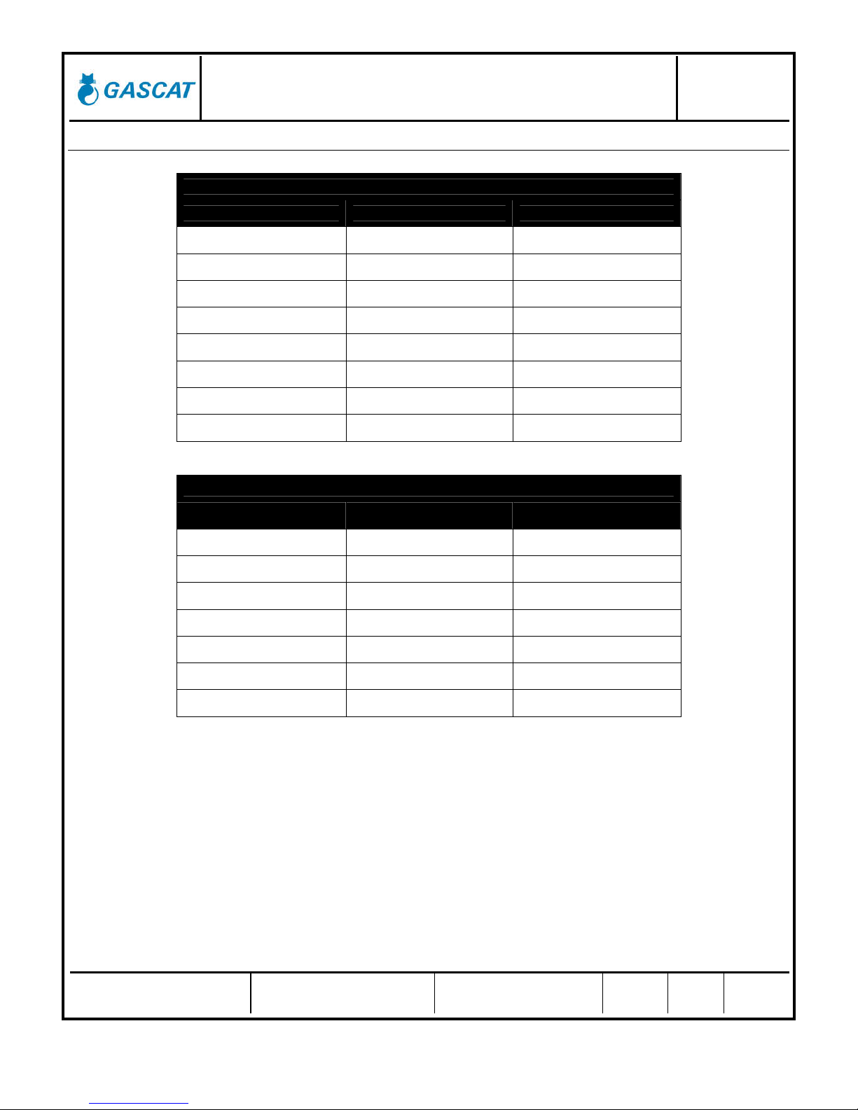
2.3.7 – PRESSURE REGULATOR SPRING RANGE (SET-POINT)
G-50 PILOT (old model)
SPRING COLOR PART NUMBER RANGE
RED 01.50.08 7,5 – 16,5 mbar
BLUE 01.50.09 12,5 – 21,0 mbar
GREEN 01.50.10 15,0 – 35,0 mbar
ORANGE 01.50.11 30,0 – 70,0 mbar
BLACK 01.50.67 55,0 – 140,0 mbar
WHITE 01.50.21 70,0 – 350,0 mbar
GREY 01.50.24 200,0 – 1000,0 mbar
BROWN 01.50.12 700,0 – 2400,0 mbar
G-80 PILOT (old model, with plane diaphragm)
SPRING COLOR PART NUMBER RANGE
YELLOW 01.53.33 20 – 60 mbar
BLUE 01.50.09 45 – 85 mbar
WHITE 01.50.21G 60 – 220 mbar
BLACK 01.50.67 170 – 320 mbar
SILVER 01.50.21P 230 – 400 mbar
GREY 01.50.24 350 – 1100 mbar
BROWN 01.50.12 1050 – 2500 mbar

Installation and Operation Manual
Brise Plus - Pressure Regulating Valve MI-23
Elaborado Verificado / Aprovado CSQ Data Revisão Página
JJ
GN JM 10/09/18 06 8 de 45
G-80 PILOT
SPRING COLOR PART NUMBER RANGE
YELLOW / GREY 01.50.09P 20 – 50 mbar
BLUE 01.53.35 40 – 130 mbar
WHITE / GREY 01.50.21A 90 – 250 mbar
SILVER 01.50.21P 230– 400 mbar
GREY 01.50.24 350 – 1100 mbar
BROWN 01.50.12 1050 – 2500 mbar
G-31 PILOT
SPRING COLOR PART NUMBER RANGE
GREEN 01.49.65 2,0 – 4,0 bar
2.3.8 – SLAM SHUT VALVE SPRING RANGE (SET-POINT)
SSV – ACTUADOR L
SPRING COLOR PART NUMBER RANGE
GREEN 01.53.46* 25 – 70 mbar
BLACK 01.53.47 50 – 150 mbar
SSV – ACTUATOR H
SPRING COLOR PART NUMBER RANGE
BLACK 01.51.98A 80 – 280 mbar
BLUE 01.53.35 200 – 340 mbar
WHITE 01.53.36 300 – 680 mbar
RED 01.53.37 650 – 1070 mbar
PURPLE 01.53.38 780 – 1200 mbar
ORANGE 01.53.51 1000 – 2100 mbar
GRAY 01.53.38H 2000 – 3600 mbar
*Note: To the ND 3” when to use the green adjusting spring, part number 01.53.46, the grey / orange color closing
spring with part number 01.52.10 must be used. To every others applications, the yellow closing spring, part number
01.50.72 must be used.
Installation and Operation Manual
Brise Plus - Pressure Regulating Valve MI-23
Elaborado Verificado / Aprovado CSQ Data Revisão Página
JJ
GN JM 10/09/18 06 9 de 45
2.3.9 – ACCURACY AND LOCK UP
Pressure regulator: AC up to 2,5% / SG up to 5%
SSV: AG up to 5
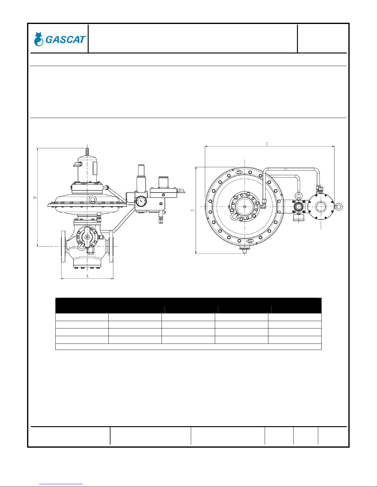
2.3.10 – PRESSURE REGULATOR DIMENSIONS (STANDARD LAYOUT)
DIMENSIONS (mm)
A (RF)
B
C
D
ND 150# / PN16 150# / PN16 150# / PN16 150# / PN16
1” 184 327 538 363
2” 254 463 621 422
3” 298 501 621 422
General Tolerance = ± 2.0
Installation and Operation Manual
Brise Plus - Pressure Regulating Valve MI-23
Elaborado Verificado / Aprovado CSQ Data Revisão Página
JJ
GN JM 10/09/18 06 10 de 45
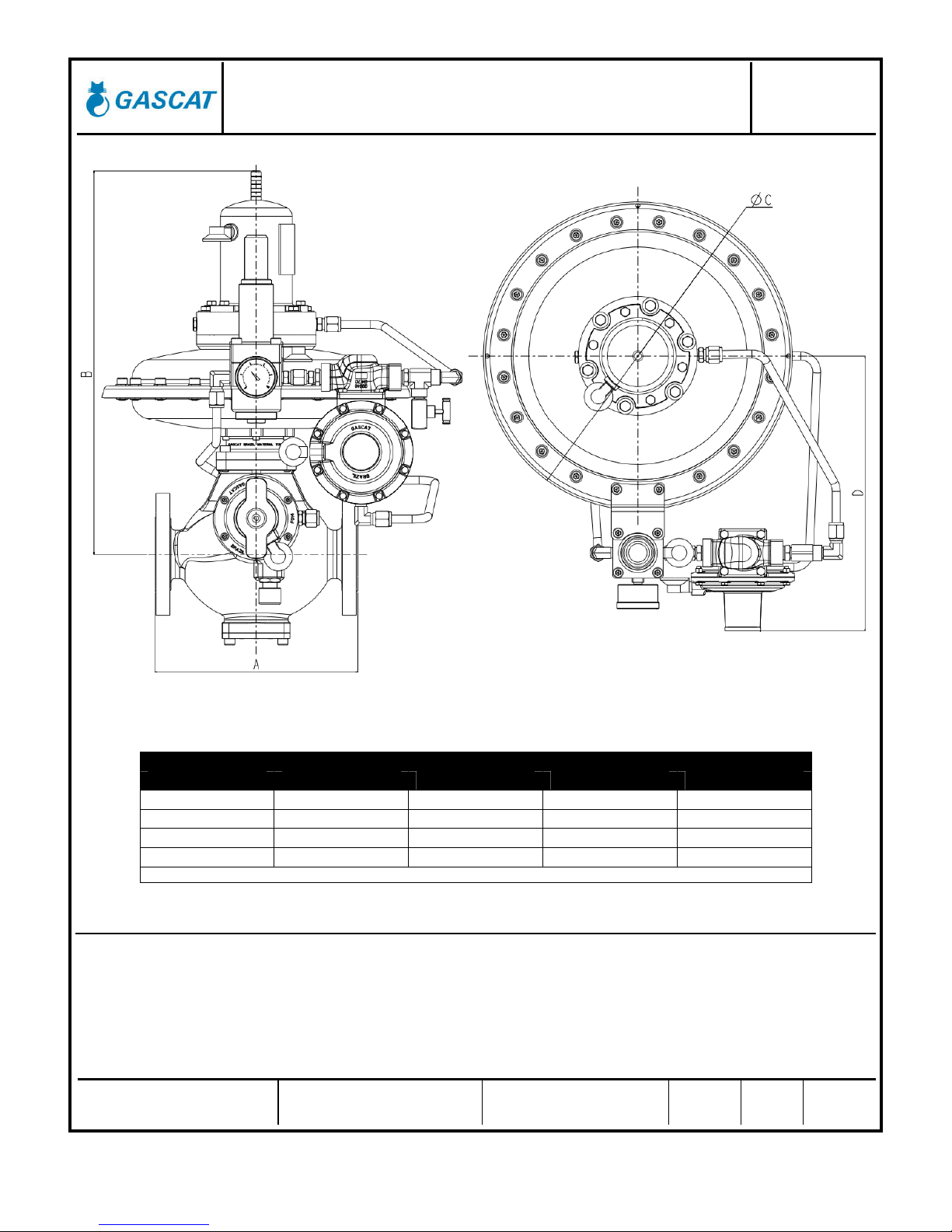
DIMENSIONS (mm)
A (RF)
B
C
D
ND 150# / PN16 150# / PN16 150# / PN16 150# / PN16
1” 184 327 290 280
2” 254 463 356 340
3” 298 501 356 340
General Tolerance = ±2.0
3 – OPERATING PRINCIPLE
Brise Plus Series works by loading pressure principle by pilot in the upper cover diaphragm of main valve that, through
the pressure differential between loading and inlet, it moves the diaphragm and, consequently, the main stem and
obturador. It increase and/or decrease the valve opening.
The outlet pressure is controlled by a low pressure pilot. An adjustable pre-regulator is usually used to assure a stable
feeding pressure to the low pressure pilot and the accuracy of the system.

Installation and Operation Manual
Brise Plus - Pressure Regulating Valve MI-23
Elaborado Verificado / Aprovado CSQ Data Revisão Página
JJ
GN JM 10/09/18 06 11 de 45
A filter is assembled upstream the pre-regulator and pilot to protect them against gas / installation impurities.
When there is gas flow, the pilot compares the outlet pressure with the adjusted pressure in the pilot spring. If the
pressure under the pilot diaphragm is lower than the desirable pressure the pilot will open and feed the upper chamber
actuator of main valve.
If the gas flow decrease or it is interrupted, then the outlet pressure begins increasing and it is compared with the
adjusted pressure in the pilot spring. If the outlet pressure is greater than the pilot set pressure, the pilot will close and the
pressure in the upper and lower chamber of the main valve will be the same; so the main valve will be closed by the force
of the closer spring.
A bleed valve assembled downstream of loading pressure will provide a variation in the gas passage orifice, increasing
or decreasing the regulator response. It also provides an opposite velocity in the closing procedure of main valve. The
equilibrium will be according to the each process.

Installation and Operation Manual
Brise Plus - Pressure Regulating Valve MI-23
Elaborado Verificado / Aprovado CSQ Data Revisão Página
JJ
GN JM 10/09/18 06 12 de 45
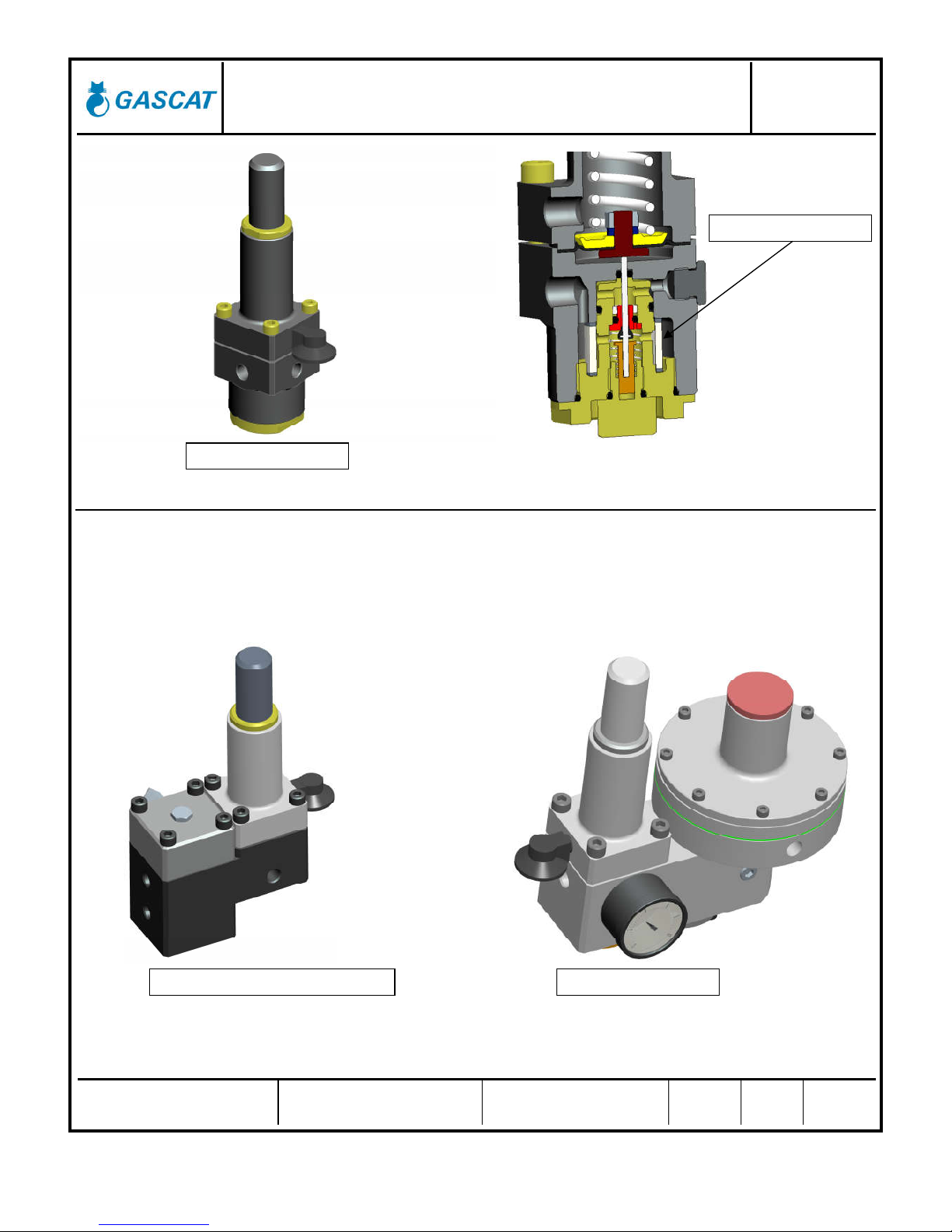
3.1 – PRE PILOT AND INTERNAL FILTER
The pressure regulator model BRISE PLUS manufacture by GASCAT can use pre pilot model G-38 or G-43 (Booster).
The function of this pre pilot is reduce the pilot inlet pressure and reduce the effects of inlet pressure variation increasing
the accuracy and performance of equipment.
G-38 pilot is assembled with an internal filter element (10 microns) to protect the pre-pilot and pilot internal against solid
contaminants as black pounder for example, however this filter must not substitute the station filter.
SIDE VIEW
Installation and Operation Manual
Brise Plus - Pressure Regulating Valve MI-23
Elaborado Verificado / Aprovado CSQ Data Revisão Página
JJ
GN JM 10/09/18 06 13 de 45
3.2 – PILOT
The pressure regulator model BRISE PLUS manufacture by GASCAT use pilot model G-80 or G-43M+31 depending of the
desired set-point. If the set-point is greater than 2.4 bar, applies the G-43M + G31.
This pilot is responsible by the control of feed pressure of main regulator actuator and by consequence of the pressure
regulator aperture.
G-38 PRE PILOT
FILTER ELEMENT
G-43 BOOSTER + G-31 PILOT
G-80 PILOT
Installation and Operation Manual
Brise Plus - Pressure Regulating Valve MI-23
Elaborado Verificado / Aprovado CSQ Data Revisão Página
JJ
GN JM 10/09/18 06 14 de 45
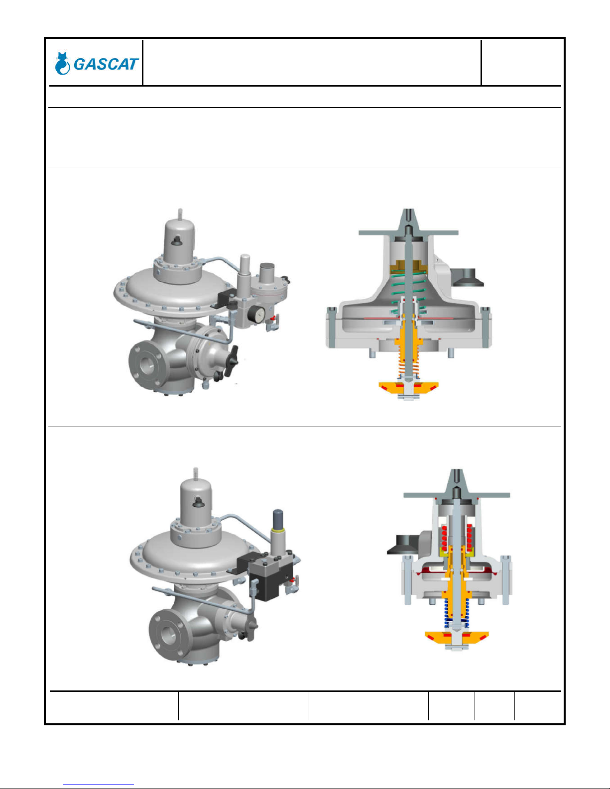
3.3 – SLAM SHUT VALVE BUILT-IN
Due to its high versatility, the BRISE PLUS regulator features two slam shut valve actuator models for
precise use at lower pressures and medium pressures.
3.3.1 – L ACTUATOR
For the lower shutting pressures (25 to 150 mbar) the BRISE PLUS regulator uses the L Actuator,
designed with a larger diaphragm area and lighter internal, proving the required sensitivity.
3.3.2 – H ACTUATOR
For medium working pressures (80 mbar to 3.5 bar) the BRISE PLUS regulator uses the H actuator, a
high rangeability and compact design.

Installation and Operation Manual
Brise Plus - Pressure Regulating Valve MI-23
Elaborado Verificado / Aprovado CSQ Data Revisão Página
JJ
GN JM 10/09/18 06 15 de 45
4 – INSTALLATION
4.1 – CHECKING SYSTEM INTEGRITY
Before installing the pressure regulator it’s necessary to insure that:
1) The equipment are in perfect conditions or has evidences of damage during the transport, in case of
perceptible damage in the equipment do not proceed with installations and get in contact with GASCAT.
2) The space provided for the acess and installation of equipment is appropriate, including future maintenance.
3) The installation was designed to support the load imposed by the equipment.
4) The inlet and outlet pipe connections are in the same level.
5) All connections for sense line and discharge line requested by the model of pressure regulator are arranged in
the pipeline and respect the dimensions provided by manufacturer.
6) Was arranged pressure indicators at the inlet and outlet of the pressure regulator to insure the correct
adjustment of set point during the commissioning.
7) Was arranged a vent line between the pressure regulator and the first block valve in the outlet of stream to help
the operator during the start-up.
8) Check the flow direction in the valve body and pay attention in the installation to assure that the valve are in the
correct position.
4.2 – PRESSURE REGULATOR NAMEPLATE
Before installation, checking is recommended to ascertain that the conditions of use are in conformity with the
specifications of the equipment. These specifications are recalled with the symbols on the plate fitted on pressure
regulator.

Installation and Operation Manual
Brise Plus - Pressure Regulating Valve MI-23
Elaborado Verificado / Aprovado CSQ Data Revisão Página
JJ
GN JM 10/09/18 06 16 de 45
4.3 – FILTER
We recommended the installation of a basket type filter, with minimum 150 mesh, as close as possible to the regulator
input, without being joined flange to flange, because, if the filter is installed immediately upstream of the regulator, it can
produce turbulence that will cause disturbances in the pressure control of the regulator. Care with the filter installation is
essential to the perfect operation of the apparatus, because, particles eventually found in the piping can lodge themselves
the seat and the shutter, damaging them and producing direct flow.
4.4 – CLEANING
Check piping cleaning before the installation of the regulator. We recommended a complete purge of the line with
nitrogen or compressed air.
4.5 – FLOW DIRECTION AND ASSEMBLY OPTIONS
Before starting the equipment installation, it is necessary to check if:
9) The equipment is in perfect conditions, or it has evidence of damage during transportation. If so, do not proceed
with the installation and contact GASCAT.
10) The space provided for access and installation of the equipment is adequate for future maintenance.
11) The installation is designed to support the load applied by the equipment.
12) The inlet and outlet connections, where the pressure regulator shall be installed, are perfectly aligned.
13) All necessary pressure-sensing pick-ups, downstream of the equipment pipeline, were provided respecting the
dimensions recommended by the manufacturer.
14) A pressure gauge, or any other pressure-measuring device, was foreseen for the upstream and downstream of the
equipment to allow for the correct setting up at the operation start-up.
15) A vent line was planned between the regulator and the first outlet shut-off valve to assist the operator during start-up.
16) Check the flow direction marked on the body of the pressure-regulating valve and pay attention at the time of its
installation so that it is properly positioned.

Installation and Operation Manual
Brise Plus - Pressure Regulating Valve MI-23
Elaborado Verificado / Aprovado CSQ Data Revisão Página
JJ
GN JM 10/09/18 06 17 de 45
4.6 – SENSE LINE
After install the pressure regulator model BRISE PLUS in the stream, you must connect the sensing lines and
discharge line as showed as follow:
The correct positioning of pressure regulators sense line in the pipeline is essential for the proper functioning of the
pressure regulator, for this reason it’s important to install the impulse take at a distance of 5 times the nominal pipe
diameter from the outlet of pressure regulator at a pipe stretch free from obstruction, with a pipe diameter sized to a
velocity not higher than 25 m/s (considering the minimum pressure and the maximum flow)
The connections of BRISE PLUS sense and discharge line are normally supplied for 10 mm OD pipe, however other
connections could be arranged under consult.
We recommend to not use pulse pick-up downstream of regulator with orifices with nominal diameter less than 3/8”.
Note: The distance and gas velocity recommended at this manual for the impulse take are generic, other values for
distance and velocity could be used under GASCAT analysis of installation, for more information get in contact
with GASCAT.
PRESSURE REGULATOR
SENSE LINE
SSV SENSE LINE
DISCHARGE LINE
We do not recommend installations of any type of block valve in the
sensing lines.
Installation and Operation Manual
Brise Plus - Pressure Regulating Valve MI-23
Elaborado Verificado / Aprovado CSQ Data Revisão Página
JJ
GN JM 10/09/18 06 18 de 45
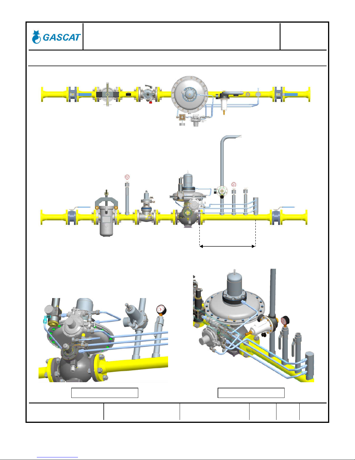
4.7 – RECOMMENDED INSTALLATION SCHEME
5 DN
VALVE CON. VIEW 1
VALVE CON. VIEW 2

Installation and Operation Manual
Brise Plus - Pressure Regulating Valve MI-23
Elaborado Verificado / Aprovado CSQ Data Revisão Página
JJ
GN JM 10/09/18 06 19 de 45
4.8 – OTHER IMPORTANT DEVICES FOR A SAFETY INSTALLATION
It is recommended for a safety installation:
1. Manual On-Off valve (sphere or similar) 6. Manometer (for outlet pressure)
2. Filter (with drain if possible) 7. Purge valve ND ½’’
3. Manometer (for inlet pressure) 8. Partial Pressure Relief Valve (CH Series)
4. Slam-shut Valve (model GIPS-L) 9. Manual On-Off valve (sphere or similar)
5. Pressure regulator + SSV (Brise Plus + G10)
1
2
3
4
5
6
7
8
9

Installation and Operation Manual
Brise Plus - Pressure Regulating Valve MI-23
Elaborado Verificado / Aprovado CSQ Data Revisão Página
JJ
GN JM 10/09/18 06 20 de 45
5 – COMMISSIONING AND START UP
5.1 – PRESSURE REGULATOR ADJUSTMENT
Always, before proceeding with the equipment commissioning it is important to:
1) Check if the equipment is properly installed according to the recommendations of item 4.5 of this manual.
2) Shut the blocking valves of the inlet, output and bypass (if applicable)
3) Open vent valve downstream of the last pressure regulator installed on the span.
4) Make sure that the station is depressurized.
5) Check if all connectors are properly secured in the station before starting pressurization of the span.
6) Check if the installed equipment has suitable operating conditions, using the information available on the
nameplate attached to the equipment.
7) Make sure that the SSV is in the shut position.
ATTENTION:
* Under no circumstances proceed with pressurization of the span where the
equipment is installed by the downstream valve of the equipment.
* Under no circumstances proceed with the depressurization of the span
where the equipment is installed by the valve located upstream of the
equipment, such as the filter drain.
ATTENTION:
GASCAT’s SSV are sent to the field already calibrated, however,
depending on transport conditions and the equipment handling the
valve may have its set point changed.
Therefore, we recommend that you check the SSV set point with the
help of an external air supply directly connected to the actuator,
before proceeding with the pressurization of the span.
The model BRISE PLUS valves are not sent to the field with adjusted
set points; this measure tends to preserve the life of the equipment
internals. Therefore, after receiving a pressure regulator valve model
BRISE PLUS, remember that you must perform the set point
adjustment before putting the equipment into operation.
The pressure reducing station setting shall be in accordance with the DIN EN 12186 / NBR 12712
standards and all other regulations in force in the region where it will operate.
Table of contents
Other Gascat Control Unit manuals


Popular Control Unit manuals by other brands


BURK Technology
BURK Technology PlusConnect Nautel GV Installation and operation manual

Jaga
Jaga DBEC.11 installation instructions

Animal Factory Amplification
Animal Factory Amplification Coma Reactor user manual

ABB
ABB COM600 series user manual

ABB
ABB REC650 ANSI Product guide

Gemu
Gemu 8357 Installation, operating and maintenance instructions

DEWESOFT
DEWESOFT V21-1 How-to guide

Conductix-Wampfler
Conductix-Wampfler 0815 Series installation instructions

AFRISO
AFRISO WaterControl 01.1 operating instructions

DITEC
DITEC EL500E Translation from original instructions

Mitsubishi Electric
Mitsubishi Electric FR-A7NL Instruction manual supplement

Precision
Precision PW66 user manual