Seiwa SI-TEX MDS-12 User manual

Radar Antenna MDS-12
WARNING AND INSTALLATION MANUAL
MAR12AMAE010
ÑMAR12AMAE010)Ó
AvMap Srl
Viale Zaccagna 6, 54033 Carrara (MS), Italy
www.seiwa-marine.com
Imported by:
1. Warranty and warnings
AvMap Srl warrants every unit to be free from defects in material and workmanship under normal
use and service for a period of 24 months from original retail purchase. During the warranty period,
AvMap Srl will repair or replace any component which fails in normal use without charges for parts
or labour. Technological developments, modications and upgrades of software are not covered by
warranty. To receive warranty service, contact your local authorized dealer for shipping instructions.
The device should be securely packed with its tracking code clearly written on the outside of the
package, shipping to be paid by the customer. Include a copy of the original sales receipt as the
proof of purchase. This limited warranty does not extend to any device which has been subjected to
misuse, neglect, accident, incorrect wiring or improper installation. AvMap Srl reserves the right to
repair or replace the device at its sole discretion.
For more warranty information please see the web site: www.seiwa-marine.com
For technical advice or assistance in Europe contact:
AvMap Srl
Viale Zaccagna 6, 54033 Carrara (MS), Italy
Customer support: +39-0585-784044
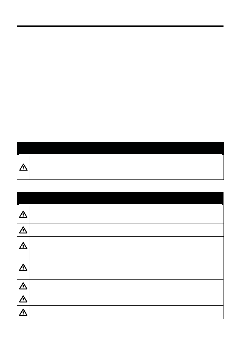
SAFETY INSTRUCTONS
“DANGER”, “WARNING” and “CAUTION” notices throughout this manual. It is the
responsibility of the operator and the installer of the equipment to read, understand and
follows these notices. If you have any questions regarding these safety instructions, please
contact the Company’s customer service or your local dealer.
WARNING
Do not open the equipment. Hazardous voltage which can cause electrical shock, burn or
serious injury exists inside the equipment. Only qualied personnel should work inside the
equipment.
Wear a safety belt and hard hat when working on the antenna unit. Serious injury or death
can result if someone falls from the radar antenna mast.
Stay away from transmitting antenna. The radar antenna emits microwave radiation which
can be harmful to the human body, particularly the eyes. Never look directly into the antenna
radiator from a distance of less than 1 m when the radar is in operation.
Turn o the radar power switch before servicing the antenna unit. Post a warning sign near
the switch indicating it should not be turned on while the antenna unit is being serviced.
Prevent the potential risk of someone being struck by the rotating antenna and exposure to
the RF radiation hazard.
Do not disassemble or modify the equipment. Fire, electrical shock or serious injury can
result.
Turn o the power immediately if water leaks into the equipment or the equipment is emitting
smoke or re. Continued use of the equipment can cause re or electrical shock.
Do not place liquid-lled containers on top of the equipment. Fire or electrical shock can
result if liquid spills into the equipment.

2. Foreword
Thank you for choosing the MDS-12 marine radar antenna. The radar antenna is designed and
constructed to meet the rigorous demands of the marine environment. However, no machine can
perform its intended function unless properly installed and maintained. Please carefully read and
follow the recommended procedures for installation, operation and maintenance. While this unit can
be installed by the purchaser, any purchaser who has doubts about his or her technical abilities may
wish to have the unit installed by an authorized Dealer or other qualied technician.
We want to Hear from you!
Your suggestions and comments are highly important to us. Please send us your feedback at
AvMap Srl
Viale Zaccagna 6, 54033 Carrara (MS), Italy
Customer support: +39-0585-784044
2.1 Features
The main features of the MDS-12 marine radar antenna:
●Built-in ethernet RJ45 connection cable to connect via a WiFi router to Seiwa Explorer 23 WiFi,
and to SWx charplotter series. (WiFi Router not included in the box).
●4kW high power all weather radar
●36NM range
●Traditional SEIWA quality and reliability in a compact, lightweight and low-cost radar antenna.
●Digital radar target technology.
●Built-in excellent sea and rain clutter algorithm.
●Fully digital signal processing.
●High performance microwave front end.
2.2 Technical Specications
ANTENNA UNIT
●Radiator: Slotted waveguide array
●Radiator length: 55 cm
●Horizontal beamwidth: 4°
●Vertical beamwidth: 25°
●Sidelobe:
●Within + 20° off mainlobe; less than -18 dB
●Outside + 20° off mainlobe; less than -23 dB
●Polarization: Horizontal
●Antenna rotation speed: 24 rpm (+ 2)
●Wind resistance: Relative wind speed 100 knots (51.5 m/s)
TRANSCEIVER MODULE (contained in radome)
●Transmitting tube: MSF1421B or MAF1421B
●Frequency: 9410 MHz + 30MHz
●Peak output power: 4kW nominal
●Pulselength & pulse repetition rate:

●0.08 μ S, 2100 Hz (0.125, 0.25, 0.5, 0.75, 1.5nm)
●0.3 μ S, 1200 Hz (1.5, 2, 3nm)
●0.8 μ S, 600 Hz (3, 4, 6, 8, 12, 16, 24, 36nm)
●Warm up time: 1:30 minutes
●Modulator: FET switching method
●I.F.: 60MHz
●Tuning: Automatic or manual
●Receiver front end: MIC (Microwave IC)
●Bandwidth:
●Tx pulselength 0.3 μ S and 0.08 μ S: 25MHz
●Tx pulselength 0.8 μ S: 3MHz
●Duplexer: Circulator with diode limiter
ETHERNET CABLE
●Ethernet cable with RJ45 connector
POWER SUPPLY UNIT
●From 10.5 Vdc to 40 Vdc built-in regulated power supply
ENVIRONMENT
●Temperature:
Antenna unit; -25°C to +70°C
●Humidity:
Relative humidity 93% or less at +40°C
●Compass safe distance:
Standard Compass Steering Compass
Antenna unit 130cm 95cm
3. Installation
This chapter provides the procedures necessary for installation. Installation mainly consists of the
following:
• sitting and mounting the display unit and antenna unit
• connection of the signal cable and the power cable
• establishing the ground
• checking the installation, and
• adjustments.
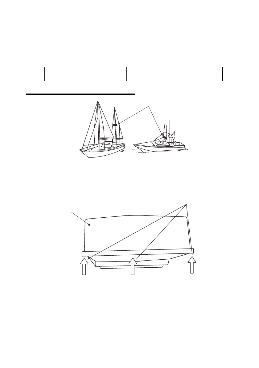
3.1 Antenna Unit Installation Sitting, handling considerations
• The antenna unit is generally installed either on top of the wheelhouse or on the radar mast on a
suitable platform. Locate the antenna unit where there is a good all-round view as far as possible,
no part of the ship’s superstructure or rigging intercepting the scanning beam. Any obstruction will
cause shadow and blind sectors. A mast for instance, with a diameter considerably less than the
width of the radiator, will cause only a small blind sector, but a horizontal spreader or crosstrees in
the same horizontal plane as the antenna unit would be a much more serious obstruction; you would
need to place the antenna unit well above or below it.
• It is rarely possible to place the antenna unit where a completely clear view in all direction is
available. Thus, you should determine the angular width and relative bearing of any shadow sectors
for their inuence on the radar at the rst opportunity after tting. (The method of determining blind
and shadow sectors appears later in this chapter.)
• If you have a radio direction nder on your boat, locate its antenna. Clear the antenna unit, to
prevent interference to the direction nder. A separation of more than two meters is recommended.
• To lessen the chance of picking up electrical interference, avoid routing the signal cable near other
onboard electrical equipment. Also avoid running the cable in parallel with power cables.
• The compass safe distance should be observed to prevent deviation of the magnetic compass.
Standard Compass Steering Compass
1.3m 0.7m
3.2 Mounting of the MDS-12 Radome
Unpacking the antenna unit
1. Open the antenna unit packing box carefully.
2. Unbolt the four bolts at the base of the redone to remove the radome cover.
Typical antenna unit location
Figure 3.2a - Radome cover
Radome cover
Bolts
Figure 3.2b - Antenna unit
3. Drill holes in the antenna mounting platform in accordance with the previous removal of the
base mounting map.
Note: the hole is arranged in parallel with the center line of the ship.
4. Loosen the antenna cover and the base of the 4 screws, carefully remove the cover.
5. Remove the cable clamping plate by unfastening four screws and removing a gasket.
6. Pass the cable through the hole at the bottom of the radome base.
7. Secure the cable with the cable clamping plate and gasket. Ground the shield and vinyl wire
by one of the screws of the cable clamping plate.

Figure 3.2.e - How to fasten the radome base to the mounting platform
8. Connect the wire to the Video Processing unit.
(1) 4-pin connector to J18
(2) RJ45 connector to J12
J18 J12
Figure 3.2.c - Antenna unit
9. Fix the shield cover. Do not pinch the cable.
Figure 3.2.d - Antenna Cable Wiring
10. Loosely fasten the radome xing bolts. You will tighten them after conrming the unit is working
normally.
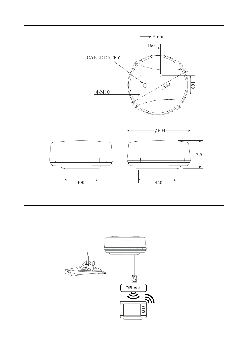
4. Drawings and dimensions
5. Connections
The radar antenna connects via ethernet cable to an external WiFi router (not included) to provide
a stable signal. Through the WiFi router, the radar antenna MDS-12 connects wirelessly to the
navigation system.
MDS-12 is compatible with SEIWA EXPLORER 23 WiFi, SWx 900 and SWx 1200 series.
Seiwa WiFi Navigation System
6. Product conformity information
6.1 Simplied EU declaration of conformity
Hereby,
SI-TEX Marine Electronics, 25 Enterprise Zone Drive suite 2, Riverhead, NY 11901, USA declares
that the radio equipments in the following table are in compliance with Directive 2014/53/EU.
Si-Tex 4kW Radar Antenna MDS-12
The full text of the EU declaration of conformity for every single product is available at the following
internet address: eudeclaration.avmap.it
5.1 Setup conguration
1. Connect your WiFi router to a PC using the WiFi router program and pre-congure the WiFi
router settings as following:
- Set the WiFi router IP Address to 223.168.1.1
- Set WiFi Router USERNAME and PASSWORD as per your preference.
In this setup conguration as example we set USERNAME to “Radar MDS-12” and
PASSWORD to ”12345678”.
- Save the settings of your WiFi router and disconnect the WiFi router from the PC.
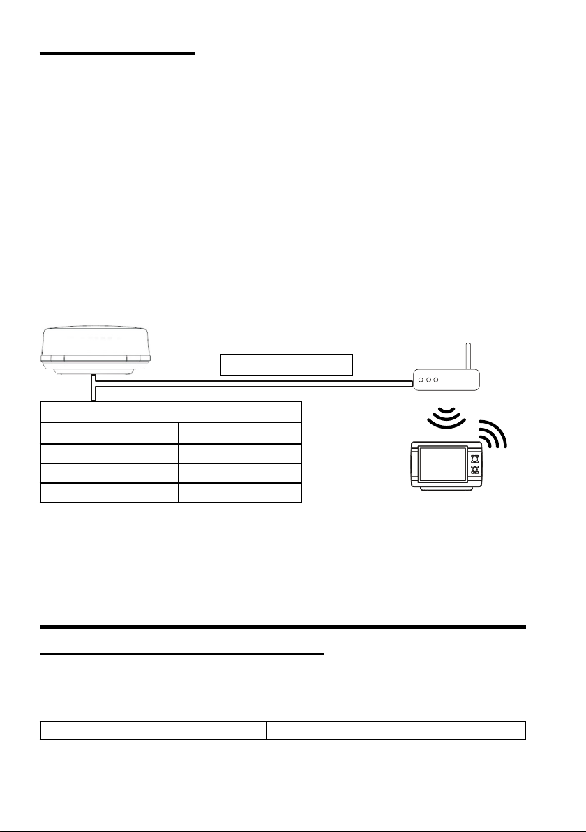
2. Connect the MDS-12 ethernet cable to the pre-congured WiFi router as shown on gure 5.1
3. Connect the radar MDS-12 to correct power source as shown on gure 5.1.
4. Power on the radar MDS-12.
5. Power on the Seiwa WiFi navigation system.
6. In the main menu of the Seiwa WiFi navigation system open the “Ports and Connectivity” menu,
select WiFi and enable Wireless LAN. After that you can select the WiFi router USERNAME
from the list of available networks. As per our example Radar MDS-12 appears on the list and
use the WiFi router PASSWORD to connect. As per our example PASSWORD “12345678”.
Note: The network will be remembered by the Seiwa WiFi navigation system and next time it will be
connected automatically.
WiFi Router
Seiwa WiFi Navigation System
Ethernet Cable
Figure 5.1
Radar Antenna MDS-12 cable
Cable color Function
Black PWR -
Red PWR + (10.5 to 40 Vdc)
Black with ring connector GND
Note: the ground wire (black cable with ring connector) is used to connect to the grounding of the
metal boat. For wooden or breglass boats it is not needed to connect the ground wire.
Note: it is suggested to add a power switch with fuse (5A for 12V and 3A for 24V) for the radar antenna.
Table of contents
Other Seiwa Radar manuals


