Carmanah Technologies Corp. | 250 Bay St, Victoria, BC V9A 3K5, Canada | 1.250.380.0052 | customersupport@carmanah.com | carmanah.com 5
3.0 Operation
When used with a single non-wireless Carmanah E, F or G system, the Radar Detection Kit triggers the system’s
RRFB light bar(s), beacon(s), or LED enhanced sign(s) to flash for a pre-set field-adjustable duration (see Output
Hold Time setting, Section 6.4). When installed with two or more Carmanah E, F or G wireless systems, one or
more Radar Detection Kits can activate all the systems’ RRFB light bars, beacons, and LED enhanced signs.
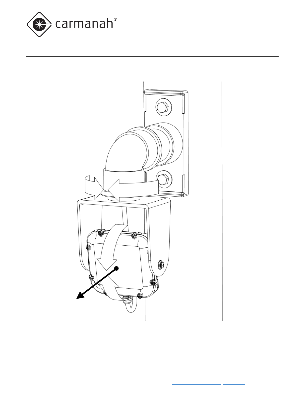
3.1 Radar Module Operation
When the radar module detects the motion of a vehicle, it shorts the button input terminals of the Carmanah
Energy Management System (EMS) to which it is connected. Once the radar module stops detecting the vehicle’s
motion, either because the vehicle has stopped or has moved out of the detection zone, it continues to hold the
button input shorted for the duration programmed in the module’s Output Hold Time setting (Section 6.4). The
default setting is 10 seconds.
3.2 Wireless Operation
When a radar-equipped wireless E/F/G system detects a vehicle, the EMS broadcasts a signal to flash any
remote wireless E/F/G systems present. Once the radar-equipped wireless system stops flashing, its EMS
broadcasts another signal to immediately extinguish the flashing of the remote systems.
The wireless Carmanah EMS can operate on 14 different Radio Channels. Wireless E/F/G systems will only
communicate with one another if they’re on the same Radio Channel. The Radio Channel is by default set to
Channel 5 and can be changed using the on-board user interface (see the E/F/G User Manual for details). Radio
Channels can be used to create groups of E/F/G systems that flash together but don’t activate nearby systems
set to a different Radio Channel.
Multiple radar-equipped wireless E/F/G systems can be used together. If you wish all systems to flash whenever a
vehicle is detected by any of the radar-equipped wireless E/F/G systems, the EMS Radio Channel must be set to
the same value in all systems (see E/F/G User Manual for details).
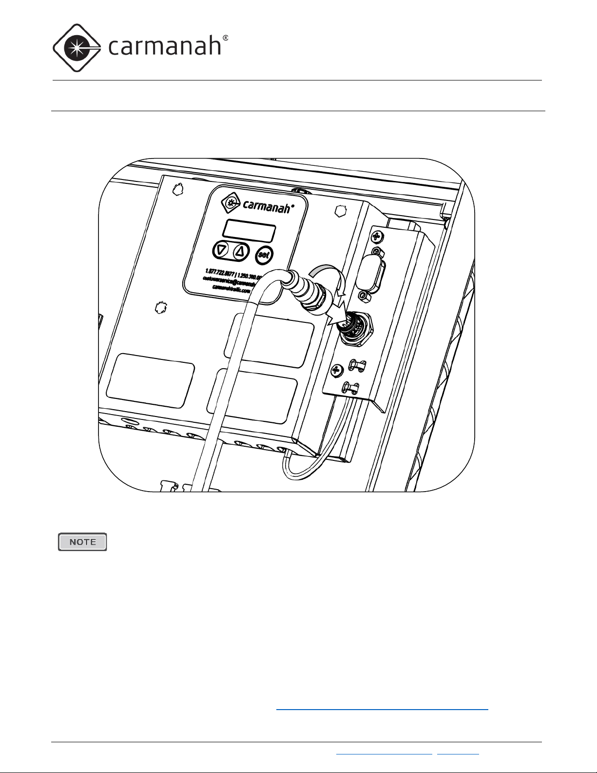
The EMS in any E/F/G system with the radar detection kit is configured to turn on the system’s
LED loads whenever its button input is shorted (EMS Input Type set to “no”, normally open).
The default EMS Radio Channel setting is Channel 5. Unless this is changed on any of the units,
all wireless E/F/G systems will flash together.