SEKUR C 700 Specification sheet
0
C701
Maschere panoramiche (IT)
Panoramic masks (EN)
Panorama Vollmasken (DE)

1

2
LINEA MASCHERE C 700
Norma EN 136:1998
Manuale uso e manutenzione
Pag. 4
Instruction for use and maintenance
Pag. 12
Informationsbroschüre
Seite 19

3

4
INDICE
1. INDICAZIONI GENERALI
2. NORME APPLICABILI, CAMPO DI IMPIEGO, PRECAUZIONI ED AVVERTENZE
2.1. PARTICOLARI CONDIZIONI DI IMPIEGO
3. MARCATURA (TIPO E MODELLO)
4. PRINCIPIO DI FUNZIONAMENTO
5. COMPONENTI DELLA MASCHERA
6. INDOSSAMENTO DELLA MASCHERA E PROVA DI TENUTA
7MANUTENZIONE, PULIZIA E DISINFEZIONE
7.1 CONTROLLI E MANUTENZIONE PERIODICA
7.2 PULIZIA
7.3 DISINFEZIONE
8 PROVA DI TENUTA CON STRUMENTAZIONE
8.1 DISPOSITIVO DI PROVA
8.2 PROVA
8.3 TENUTA DELLA MASCHERA E DELLA VALVOLA DI ESPIRAZIONE
9 TRASPORTO, IMMAGAZZINAMENTO E SMALTIMENTO
10 CONSIGLI DI MANUTENZIONE SPECIFICI E SOSTITUZIONE DELLE PARTI DI RICAMBIO
10.1 SOSTITUZIONE DELLA SEMIMASCHERA INTERNA (FIGURA 3)
10.2 SOSTITUZIONE DEL BOCCHETTONE (FIGURA 4)
10.3 SOSTITUZIONE DELLO SCHERMO (FIGURA 5)
10.4 SOSTITUZIONE DELLA VALVOLA DI ESPIRAZIONE (FIGURE 6)
10.5 SOSTITUZIONE DELLA VALVOLA DI INSPIRAZIONE (FIGURA 7)
11 CODICI ARTICOLO, PARTI DI RICAMBIO, ACCESSORI
FIGURE, FIGURES, ABBILDUNGEN

5
1. Indicazioni generali
SEKUR é il marchio registrato dei dispositivi di protezione individuale prodotti dalla D.P.I. s.r.l. Non sono
consentite modifiche tecniche di questi prodotti.
1.1 L'impiego delle maschere SEKUR della serie C 700 presuppone la conoscenza e l'osservanza di questo
manuale di istruzioni.
1.2 Le maschere SEKUR sono destinate unicamente all'impiego descritto nel manuale di istruzioni.
1.3 Riparazioni e sostituzioni delle parti componenti possono essere eseguite solo da personale specializzato,
impiegando ricambi originali SEKUR.
1.4 Si consiglia di far eseguire dal Servizio di Assistenza della D.P.I. s.r.l., o da altro personale specializzato,
controlli periodici della maschera secondo quanto riportato nel paragrafo dedicato.
1.5 La D.P.I. s.r.l. si assume le responsabilità previste dalle condizioni generali di contratto. Non si assume
responsabilità quando:
a) non siano stati effettuati controlli,
b) i controlli, ovvero la manutenzione sia stata eseguita in maniera non adeguata da personale non
appartenente alla D.P.I. s.r.l.,
c) la maschera non sia stata impiegata in modo adeguato.
1.6 La D.P.I. s.r.l. non risponde dei danni causati dall'inosservanza del manuale di istruzioni.
1.7 Per quanto non menzionato valgono le condizioni generali di contratto della D.P.I. s.r.l. Nel caso non siate
a conoscenza delle suddette condizioni. Vi saranno inviate su richiesta dalla D.P.I. s.r.l.
2. Norme applicabili, campo di impiego, precauzioni ed avvertenze
Obiettivo delle maschere della serie C 700 è la protezione delle vie respiratorie di un soggetto che si trovi in un
ambiente con presenza di aria non respirabile. In questo contesto la funzione specifica della maschera è quella
di isolare l’apparato respiratorio dell’utilizzatore dall’aria proveniente dall’ambiente esterno e non respirabile.
Le maschere della serie C 700 sono DPI classificati in III categoria, come definito nel Regolamento (UE) 425/2016,
e conformi ai requisiti prestazionali specificati nella norma EN 136:98 classe 3 ovvero per impiego speciale, il
modello C 701 è dotato di raccordo filettato a norma EN 148-1. Le maschere non sono idonee all’utilizzo in tutte
le atmosfere potenzialmente esplosive. Nel caso di necessità di utilizzo in tali circostanze contattare la D.P.I. s.r.l.
Le prove sulle maschere secondo la relativa norma EN e la certificazione con autorizzazione alla marcatura CE
sono state eseguite dall’Organismo Notificato Italcert - Viale Sarca, 336 - 20126 Milano.
La marcatura CE sull’armatura delle maschere “CE 0426“attesta il rispetto dei requisiti essenziali di salute e
sicurezza previsti dal Regolamento 2016/425 ed identifica l'organismo che ne effettua il controllo sulla
produzione secondo la procedura prevista dall’allegato VIII del Regolamento (UE) 425/2016 - Italcert - Viale Sarca,
336 - 20126 Milano - Italia (Organismo Notificato n. 0426).
Il visore delle maschere della serie C700 è conforme alla norma STANAG2920 (ed. 3):2015 Measurament of V50
(Ballistic test, FSP= caliber 22 type 1) e secondo la norma EN 166:2001 Personal eye-protection -§7.1.2.1
“Spherical, astigmatic and prismatic refractive powers” raggiungendo la classe ottica I.
Devono essere assolutamente osservate le istruzioni per l’uso dei filtri, nonché le norme e le disposizioni delle
autorità competenti in materia di sicurezza. Gli utilizzatori di dispositivi di protezione delle vie respiratorie
devono essere sani e ben addestrati all’uso di questi sistemi. Devono essere privi di lunghe basette, baffi e barba
poiché questi potrebbero interferire col bordo di tenuta della maschera non consentendo un’adeguata tenuta al
viso. L’utilizzo di queste maschere è vincolato alla presenza di una quantità di ossigeno maggiore del 18%,
temperatura compresa tra 0°C e 50°C e presenza di limitate quantità di vapore acqueo. Nell’impiego delle
maschere della serie C 700 devono essere rispettate le massime concentrazioni di contaminante consentite
nell’atmosfera ambiente. I valori limite sono indicati nel manuale di istruzione dei filtri utilizzati con la maschera.
Se il dispositivo entra in contatto con oli e derivati del petrolio, solventi, agenti ossidanti, acetati, acqua
ossigenata, acidi e basi forti lavare con cura come riportato nel paragrafo 7.2.
In base ai limiti massimi di penetrazione stabiliti dalla EN 136 una maschera a pieno facciale, se correttamente
indossata ed utilizzata rispettando tutte le avvertenze e le limitazioni presenti in questo manuale, soddisfacendo
il requisito di “perdita di tenuta verso l’interno” assicura una penetrazione massima dello 0,05% cui va sommata
la penetrazione attraverso l’elemento filtrante.
Secondo la definizione di Fattore di Protezione Nominale (FPN), definito come 100 diviso la perdita totale verso
l’interno percentuale massima consentita, la maschera assicura un FPN pari a 2000.
In base a quanto previsto dal D. Lgs. 81/08, confermato dalla GU n°.59 del 11/02/2019, con riferimento ai Dpi di
III categoria cui le maschere intere appartengono, il loro uso presuppone il preventivo addestramento.

6
2.1. Particolari condizioni di impiego
Quando pericoli richiedono oltre alla protezione degli organi respiratori anche altre attrezzature di protezione,
deve essere verificate attentamente la compatibilità di queste attrezzature con la maschera. Queste misure di
protezione supplementari non devono pregiudicare la piena efficacia del dispositivo di protezione delle vie
respiratorie.
Pericoli di questo genere possono essere tra gli altri:
−sostanze liquide o gassose dannose per la pelle,
−sostanze tossiche irritanti per la pelle,
−radiazioni,
−azioni meccaniche,
−esplosioni nell’atmosfera ambiente,
−atmosfera arricchita di ossigeno.
In caso di dubbio il Servizio di Assistenza della D.P.I. s.r.l. è a Vostra disposizione per consigli e chiarimenti.
3. Marcatura (Tipo e modello)
Le maschere della serie C 700 sono marcate CE come previsto dal Regolamento (UE) 2016/ 425 poiché i campioni
esaminati sono stati trovati rispondenti ai requisiti richiesti dalla norma EN 136:98. L’identificazione dei rispettivi
modelli si realizza sulla base dei seguenti elementi e simboli di riconoscimento.
Modello
Raccordo filettato
Valvola di espirazione
Colore distintivo di
armatura e griglietta
Materiale del corpo della
maschera
C 701 BLACK
EN 148-1
Pressione negativa
Nero
Termoplastico
C 701 RED
EN 148-1
Pressione negativa
Rosso
Termoplastico
C 701 ORANGE
EN 148-1
Pressione negativa
Arancione
Termoplastico
C 701 GREEN
EN 148-1
Pressione negativa
Verde nato
Termoplastico
C 701 WHITE
EN 148-1
Pressione negativa
Bianco
Termoplastico
C 701 TEAL
EN 148-1
Pressione negativa
Verde acqua
Termoplastico
L’intera maschera
C 701... = Modello (Parte bassa griglietta bocchettone)
= LOGO Identificativo del produttore (sulla zona centrale dell’armatura)
CE 0426 = Marchio CE e numero identificativo dell’ente omologante che ne effettua il controllo sulla
produzione (sull’armatura)
EN 136:1998 = Norma di riferimento (sull’armatura)
CL 3 = Classe di appartenenza della maschera secondo UNI EN 136 (“Cl3”sull’armatura)
Valvola di Espirazione
data stampaggio, sulla valvola
Bardatura
data di stampaggio su zona centrale,
codice identificativo della bardatura su zona centrale
Semimaschera Interna
data stampaggio posizionata all’interno,
codice identificativo posizionato all’interno
Facciale
data stampaggio posizionata all’interno,
codice identificativo posizionato all’interno
Griglietta Bocchettone
nome della maschera posizionata nella parte inferiore esterna
Armatura
numero codice di ricambio
La dichiarazione di conformità dei prodotti è disponibile sul sito www.dpisekur.com, nella sezione relativa al
dpi.
4. Principio di funzionamento
L’aria inspirata attraverso la valvola di inspirazione contenuta nel bocchettone raggiunge l’interno della maschera
e scorre lungo la parte interna dello schermo evitandone l’appannamento. L’aria inspirata passa attraverso setti
nella mascherina interna. L’aria utilizzata viene poi espulsa nell’atmosfera circostante attraverso una valvola di
espirazione.

7
5. Componenti della maschera
Le maschere della serie C 700 si compongono degli elementi rappresentati e indicati in figura 1 ed in figura 2.
6. Indossamento della maschera e prova di tenuta
Le maschere della serie C 700 sono disponibili nella taglia media che si adatta alla maggior parte dei visi.
Per l’indossamento con bardatura in gomma seguire le istruzioni seguenti:
6.1 Mediante le fibbie di regolazione allentare i cinque tiranti della bardatura
6.2 Distendere i due tiranti della bardatura nucale
6.3 Porre la maschera davanti al viso tenendola per la bardatura nucale. Appoggiare il mento nell’apposito
incavo della maschera e passare la bardatura sulla testa
6.4 Verificare che l’area pentagonale di incontro dei bracci della bardatura si posizioni nella nuca. Se risultasse
troppo distante accorciare il tirante frontale (oppure accorciarlo se fosse troppo in basso) ed adattare la
tensione degli altri bracci della bardatura alla nuova posizione.
6.5 Successivamente tirare i tiranti della bardatura seguendo questo ordine “Nucali”, “Temporali” e “Frontale”.
I tiranti nucali e temporali della bardatura dovrebbero essere regolati possibilmente in coppia e con due
mani. Infine tirare la bardatura frontale. La bardatura deve essere regolata in modo tale che si avverta sul
viso una pressione uniforme del bordo di tenuta della maschera.
6.6 Dopo aver indossato la maschera e prima dell’uso, effettuare una prova di tenuta. Chiudere il bocchettone
con il palmo della mano e inspirare in modo tale che la maschera aderisca sul viso. Non deve essere
avvertibile alcuna infiltrazione d’aria in nessun punto della maschera. La prova di tenuta deve essere
ripetuta 2-3 volte. La maschera può essere impiegata solo dopo aver superato la prova di tenuta.
6.7 Per togliere la maschera allentare le bardature seguendo lo stesso ordine usato nella procedura di
indossamento. Spingere le fibbie in avanti con il pollice. Sfilare la maschera dal mento e successivamente
sollevarla dalla testa.
Attenzione: se la prova di tenuta descritta nel paragrafo 6.6 non viene superata ripeterla fino al
raggiungimento della tenuta. L’uso della maschera che non abbia una tenuta sufficiente può causare danni
irreparabili alla salute dell’utilizzatore.
Per l’indossamento con bardatura in tela seguire le istruzioni seguenti:
6.8 Sganciare i tiranti dal velcro.
6.9 Regolare preliminarmente il tirante centrale ed i tiranti superiori laterali in funzione della dimensione del
volto, in modo che il mento risulti appoggiato nell’apposito incavo e la fronte appoggiata al lembo interno
della maschera. All’aumentare delle dimensioni della testa lasciare i tiranti più lunghi.
6.10 Tenere la maschera per la bardatura nucale e passare la bardatura sulla testa
6.11 Regolare i tiranti laterali inferiori della bardatura. La bardatura deve essere regolata in modo tale che si
avverta sul viso una pressione uniforme del bordo di tenuta della maschera. Se necessario disindossare la
maschera e aggiustare la regolazione dei tre tiranti superiori.
6.12 Dopo aver indossato la maschera e prima dell’uso, effettuare una prova di tenuta. Chiudere il bocchettone
con il palmo della mano e inspirare in modo tale che la maschera aderisca sul viso dell’utilizzatore. Non
deve essere avvertibile alcuna infiltrazione d’aria in nessun punto della maschera. La prova di tenuta deve
essere ripetuta 2-3 volte. La maschera può essere impiegata solo dopo aver superato la prova di tenuta.
6.13 Per togliere la maschera sganciare il velcro dei tiranti laterali inferiori. Sfilare la maschera dal mento e
successivamente sollevarla dalla testa.
Attenzione: se la prova di tenuta descritta nel paragrafo 6.12 non viene superata ripeterla fino al
raggiungimento della tenuta. L’uso della maschera che non abbia una tenuta sufficiente può causare danni
irreparabili alla salute dell’utilizzatore.
7Manutenzione, pulizia e disinfezione
Per mantenere le maschere della serie C 700 in perfetta efficienza é necessario sottoporle periodicamente alla
manutenzione, pulizia e disinfezione, secondo quanto riportato nella tabella sottostante.
8
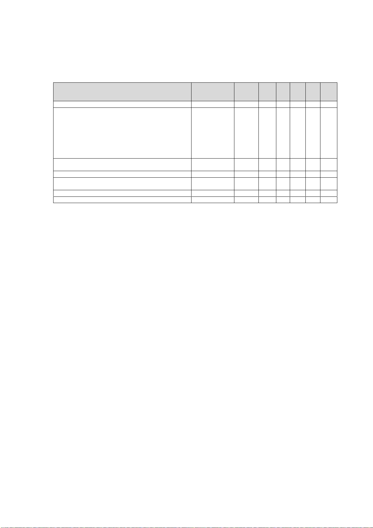
7.1 Controlli e manutenzione periodica
L’utilizzatore deve assicurarsi che vengano eseguiti i controlli di manutenzione periodica del dispositivo di
protezione delle vie respiratorie come previsto nel manuale di istruzioni fornito dal produttore.
Tipo di operazione da eseguire
Prima
dell’autorizzazione
all’uso
Prima di
ogni uso
Dopo
l’uso
Ogni 6
mesi
Ogni
anno
Ogni 2
anni
Ogni 6
anni
Pulizia e disinfezione
X
X (1)
Controlli visivi:
•presenza di graffi o crepe sullo schermo
•segni visibili di surriscaldamento (2)
•tagli o screpolature sulla gomma
•presenza e integrità della guarnizione di ispirazione sul
bocchettone
•presenza e integrità della valvola di ispirazione e di espirazione
•tirare a mano la bardatura e verificarne l’integrità
X
X
X
Prove di tenuta statica in depressione (3) eseguita
dall’utilizzatore
X
X
Prova di tenuta con strumentazione
X (1)
X
Sostituzione della guarnizione di ispirazione, della bardatura e
delle guarnizioni
X
Sostituzione della valvola di ispirazione e valvola di espirazione
X
Controllo della filettatura con il calibro
X
Legenda:
(1) Anche in assenza di uso, a meno che non sia conservata in confezione chiusa ermeticamente.
(2) Solo se esposta a fonti di calore.
(3) La prova consiste nel verificare che non si avvertano apprezzabili perdite di aria dalla maschera dopo averla indossata e
aver chiuso con il palmo della mano il raccordo di inspirazione, creando una lieve depressione nella maschera tentando
di inspirare.
7.2 Pulizia
La pulizia delle maschere deve essere eseguita dopo ogni impiego per assicurare all’utilizzatore un’igiene
adeguata. La mancata pulizia oltre a portare problemi igienici può pregiudicare il funzionamento del dispositivo.
Il lavaggio può essere svolto in modo tradizionale a immersione in acqua, o a ultrasuoni. In entrambi i casi, in
funzione della necessità di procedere a una pulizia a fondo, legata alla condizione della maschera, si può
smontare e lavare separatamente tutti i componenti.
Il lavaggio a ultrasuoni deve essere svolto con macchinari SONOREX SUPER RK514BH o RK1028CH che possono
essere forniti dalla D.P.I. s.r.l.. L’utilizzo di macchinari diversi può pregiudicare il funzionamento della maschera.
Il lavaggio a ultrasuoni deve essere effettuato ad una temperatura di controllo non superiore a 40°C ed
utilizzando un leggero detersivo diluito al 5% in acqua.
Il lavaggio tradizionale può essere svolto con acqua tiepida e con un leggero detersivo diluito al 5% in acqua. In
entrambi i casi non utilizzare mai solventi!
Dopo il lavaggio procedere al risciacquo con acqua corrente e all’asciugatura con aria o in speciali armadi
evitando comunque l’esposizione diretta a radiazione solare. Durante tale fase porre particolare attenzione alla
durata e non esporre le maschere al contatto localizzato con punti caldi o con aria surriscaldata (superiore ai
45°C) per evitare di rovinare le parti in gomma. Controllare che al termine delle operazioni non rimangano tracce
di detersivo altrimenti ripetere il risciacquo e l’asciugatura. Se la maschera è stata smontata per il lavaggio si
deve effettuare la prova di tenuta con la strumentazione. Qualora la maschera sia stata esposta a sostanze
chimiche particolarmente tossiche, biologiche o radioattive, la manutenzione diventa straordinaria e deve essere
eseguita da personale specializzato o dal Servizio di Assistenza della D.P.I. s.r.l..
7.3 Disinfezione
La disinfezione della maschera risulta necessaria se viene indossata da diversi utilizzatori per prevenire problemi
igienici e sanitari. La disinfezione può essere svolta in un contenitore dopo il lavaggio o se preferito, anche con il
macchinario SONOREX SUPER RK514BH o RK1028CH che possono essere forniti dalla D.P.I. s.r.l.. Si deve tenere
presente che lo sgrassante ed il disinfettante si annullano a vicenda, se usati contemporaneamente quindi si
devono effettuare due bagni separati lavando con particolare cura la vasca tra i due. La disinfezione può essere
svolta solo con disinfettanti autorizzati diluito al 5% in acqua. Sciacquare infine con acqua corrente e asciugare.
Attenzione: per la pulizia e la disinfezione non utilizzano solventi (come acetone e alcool) o sostanze abrasive.
Attenersi esclusivamente alla procedura descritta nei due punti precedenti e utilizzare solo il detergente e
disinfettante ivi indicati. Detersivi, tempi di dosaggio o di esposizione diversi da quelli indicati possono
danneggiare la maschera.

9
Il detergente non diluito può essere dannoso per la salute. Quindi, maneggiare con cura indossando occhiali e
guanti protettivi.
8Prova di tenuta con strumentazione
Nel caso in cui la maschera sia stata smontata per essere pulita o per sostituire parti componenti, deve essere
successivamente eseguita una prova di tenuta. Prima di eseguire la prova di tenuta effettuare un controllo visivo.
Le valvole, i seggi e la guarnizione devono essere puliti. Le parti difettose devono essere sostituite. La maschera
non può essere utilizzata se non ha superato il test di tenuta.
8.1 Dispositivo di prova
Il dispositivo di prova si compone di una testa di gomma gonfiabile, di un’imboccatura di raccordo in
corrispondenza della bocca, di un banco e di un tappo per chiudere il raccordo di inspirazione.
L’apparecchio di collaudo consente, la prova di tenuta sia in pressione positiva che negativa.
8.2 Prova
Sistemare la maschera da provare sulla testa gonfiabile (eventualmente bagnandone la superficie con acqua) e
serrare la bardatura. Gonfiare fin quando la testa rimanga stabile ed aderente attorno al bordo di tenuta della
maschera. Regolare eventualmente la bardatura. Posizionare il tappo a tenuta sul raccordo di inspirazione della
maschera. Osservare i comandi dell’apparecchio di prova come da manuale istruzioni.
8.3 Tenuta della maschera e della valvola di espirazione
La maschera e la valvola di espirazione rispondono ai requisiti di tenuta richiesti, quando in condizioni di umidità
della valvola di espirazione con una depressione di 10 mbar (1000 Pa) all’interno della maschera, il cambiamento
di pressione non sia superiore a 1 mbar (100 Pa) al minuto. Quando la prova avrà ottenuto un esito positivo,
togliere la maschera dalla testa di prova ed eventualmente asciugarla. La maschera potrà essere usata solo dopo
aver superato la prova di tenuta.
9Trasporto, immagazzinamento e smaltimento
Le maschere devono essere conservate a temperatura normale, non superiore ai 50°C, protette da azioni
dannose quali i raggi diretti del sole, caldo, freddo, umidità, sostanze con effetti corrosivi sulla gomma, urti,
cadute, polvere e sporco. I prodotti in termoplastico elastomero non devono essere sottoposti a tensioni o
pressioni, devono essere cioè conservati in modo da evitarne la deformazione per compressione. Le maschere
devono essere conservate nelle loro scatole di imballo originali o nelle loro borse custodia o in appositi armadi.
Le maschere della serie C700, in quanto tali, non sono considerate rifiuti speciali e rientrano nel codice
CER150203 e vanno smaltiti tenendo conto che i loro principali materiali componenti sono:
-Gomma e silicone;
-plastica;
-metallo (modeste quantità).
Particolari accortezze nel rispetto delle disposizioni di legge vanno adottate in funzione del loro eventuale livello
di contaminazione, in base alle loro condizioni di utilizzo, al momento dello smaltimento in quanto in tal caso
rientrano nel codice CER150202.
Per il trasporto utilizzare l’imballaggio originale.
10 Consigli di manutenzione specifici e sostituzione delle parti di ricambio
Quando la maschera viene smontata e successivamente rimontata per scopi di pulizia e disinfezione bisogna
adottare la stessa procedura della sostituzione delle parti, a condizione che non sia stato stabilito diversamente.
Assicuratevi durante il montaggio che tutte le parti siano state montate in modo corretto e di eseguire le
operazioni con cura al fine di non danneggiare la maschera.
10.1 Sostituzione della semimaschera interna (Figura 3)
Smontare la semimaschera interna scalzandola dal bocchettone. Montare la nuova semimaschera calzandola
all’interno della gola del corpo bocchettone. Centrarla attraverso i riscontri superiori della semimaschera con il
perno del bocchettone.
10.2 Sostituzione del bocchettone (Figura 4)
Rimuovere la semimaschera interna come descritto al punto 10.1. Rimuovere la griglietta esterna spostando il
dentino superiore attraverso l’inserimento di un utensile (ad esempio un cacciavite di larghezza massima 4mm e
di spessore massimo 1mm o equivalente) nella fessura della griglietta disposta appena al di sopra del raccordo

10
filettato e spostare l’utensile verso il basso in modo che l’estremità all’interno della griglietta vada verso l’alto;
quindi svincolare dal corpo bocchettone la griglietta sganciando il dentino inferiore. Rimuovere il bocchettone
ruotandolo in senso antiorario. Sostituire l’OR 57X2 sul bocchettone quindi rimontare il bocchettone sul nuovo
visore, inserendolo e ruotandolo in senso orario. Riassemblare la semimaschera interna come descritto al punto
10.1. Infine applicare la griglietta fino ad avvertire lo scatto dei due dentini.
10.3 Sostituzione dello schermo (Figura 5)
Svitare la vite che si trova nella parte inferiore dell’armatura. Togliere l’armatura, quindi togliere il facciale.
Rimuovere il bocchettone e la semimaschera come descritto al punto 10.2. Rimontare il facciale facendo
coincidere le linee superiori ed inferiori di visore e facciale. Infilare l’armatura nella propria sede intorno al
facciale: per primo posizionare la “T” superiore, per secondo la parte più in basso quindi tirare i tiranti laterali,
infine serrare la vite. Rimontare il bocchettone e la semimaschera come descritto al punto 10.2 ed al punto 10.1.
Applicare la griglietta fino ad avvertire lo scatto dei due dentini.
10.4 Sostituzione della valvola di espirazione (Figure 6)
Rimuovere la semimaschera dal bocchettone. Smontare la sede della valvola di espirazione dal bocchettone
attraverso l’inserimento di un utensile (ad esempio un cacciavite di larghezza massima 4mm e di spessore
massimo 1mm o equivalente) nella fessura superiore e ruotarlo in senso orario. Sostituire la valvola di
espirazione. Riassemblare la sede della valvola di espirazione inserendola e ruotandola in senso orario fino allo
scatto del perno superiore. Infine riassemblare la semimaschera interna come descritto nel punto 10.1.
10.5 Sostituzione della valvola di inspirazione (Figura 7)
Per sostituire la valvola di inspirazione è necessario rimuovere la semimaschera ed il bocchettone come descritto
nel punto 10.3 e 10.2. Rimuovere il fermo valvola di inspirazione dal bocchettone attraverso l’inserimento di un
utensile nelle sedi laterali. Sostituire la valvola di inspirazione inserendo facendo coincidere i due fori con i due
perni del fermo valvola di inspirazione. Rimontare il fermo valvola di inspirazione sul bocchettone facendo
scorrere la valvola di inspirazione sulla base fino ad avvertire il doppio click dei perni laterali. Rimontare
bocchettone e semimaschera come descritto nel punto 10.3 e 10.2.
11 Codici Articolo, Parti di Ricambio, Accessori
Articolo
Codice
Maschera C 701 nera con bardatura in gomma
43335000B
Maschera C 701 verde acqua con bardatura in gomma
43335000G
Maschera C 701 verde militare con bardatura in gomma
43335000M
Maschera C 701 rossa con bardatura in gomma
43335000R
Maschera C 701 bianca con bardatura in gomma
43335000W
Maschera C 701 arancione con bardatura in gomma
43335000O
Maschera C 701 nera con bardatura in tela
43335001B
Maschera C 701 verde acqua con bardatura in tela
43335001G
Maschera C 701 verde militare con bardatura in tela
43335001M
Maschera C 701 rossa con bardatura in tela
43335001R
Maschera C 701 bianca con bardatura in tela
43335001W
Maschera C 701 arancione con bardatura in tela
43335001O
Maschera C 701 nera con bardatura in gomma visore trattato
43335010B
Maschera C 701 verde acqua con bardatura in gomma visore trattato
43335010G
Maschera C 701 verde militare con bardatura in gomma visore trattato
43335010M
Maschera C 701 rossa con bardatura in gomma visore trattato
43335010R
Maschera C 701 bianca con bardatura in gomma visore trattato
43335010W
Maschera C 701 arancione con bardatura in gomma visore trattato
43335010O
Maschera C 701 nera con bardatura in tela visore trattato
43335011B
Maschera C 701 verde acqua con bardatura in tela visore trattato
43335011G
Maschera C 701 verde militare con bardatura in tela visore trattato
43335011M
Maschera C 701 rossa con bardatura in tela visore trattato
43335011R
Maschera C 701 bianca con bardatura in tela visore trattato
43335011W
Maschera C 701 arancione con bardatura in tela visore trattato
43335011O
Parti di ricambio
Codice
Bardatura in gomma completa di fibbie
42010305
Bardatura (solo gomma)
42010306
Bardatura (solo tela)
42010307

11
Kit fibbie per bardatura in gomma
42010308
Schermo
42010304
Schermo con trattamento
42010313
Armatura nera con vite e dado
42010310B
Armatura verde acqua con vite e dado
42010310G
Armatura verde militare con vite e dado
42010310M
Armatura rossa con vite e dado
42010310R
Armatura bianca con vite e dado
42010310W
Armatura arancione con vite e dado
42010310O
Griglia di protezione nera
42010311B
Griglia di protezione verde acqua
42010311G
Griglia di protezione verde militare
42010311M
Griglia di protezione rossa
42010311R
Griglia di protezione bianca
42010311W
Griglia di protezione arancione
42010311O
Facciale
42010302
Facciale bianco
42010302W
Semimaschera interna
42010303
Semimaschera interna bianca
42010303W
Kit n°5 valvole di inspirazione
42010309
Kit n°5 valvole di espirazione
42010135
Accessori
Codice
Lavamaschere 17 litri /2 maschere
44370270
Lavamaschere 41 litri /6 maschere
44370300
Detergente e disinfettante per lavamaschere
44370730
Pellicola protettiva antigraffio per il visore
42010027
Borsa custodia MORBIDA da trasporto
42010017
Montatura per lenti correttive
42010312

12
INDEX
1. GENERAL INFORMATION
2. APPLICABLE STANDARDS, FIELD OF APPLICATION, CAUTIONS AND WARNINGS
2.1. SPECIFIC USAGE
3. MARKING (TYPE AND MODEL)
4. OPERATING PRINCIPLES
5. MASK COMPONENTS
6. DONNING AND TIGHTNESS TEST
7. MAINTENANCE, CLEANING AND DISINFECTION
7.1. CHECKS AND PERIODIC MAINTENANCE
7.2. CLEANING
7.3. DISINFECTION
8. TIGHTNESS TEST WITH TEST EQUIPMENT
8.1. TEST RIG
8.2. TESTING
8.3. LEAK TIGHTNESS OF MASK AND EXHALATION VALVES
9. TRANSPORT, STORAGE AND DISPOSAL
10. SPECIFIC MAINTENANCE INSTRUCTIONS AND REPLACEMENT OF SPARE PARTS
10.1.REPLACEMENT OF INNER MASK (FIGURE 3)
10.2.REPLACEMENT OF THREADED CONNECTOR (FIGURE 4)
10.3.REPLACEMENT OF VISOR (FIGURE 5)
10.4.REPLACEMENT OF EXHALATION VALVE (FIGURE 6)
10.5.REPLACEMENT INHALATION VALVE (FIGURE 7)
11. REFERENCE NUMBERS FOR ORDERS, SPARE PARTS, ACCESSORIES
FIGURE, FIGURES, ABBILDUNGEN

13
1. General information
SEKUR is the registered trademark of the personal protective equipments manufactured by D.P.I. s.r.l. Technical
alterations of this equipment are not allowed.
L'impiego delle maschere SEKUR della serie C 700 presuppone la conoscenza e l'osservanza di questo manuale di
istruzioni.
1.1. SEKUR masks have been specifically designed for the use described in this manual.
1.2. Repair and replacement of spare parts must be carried out by trained personnel, using original SEKUR spare
parts.
1.3. It is advisable for all periodic mask testing to be carried out by D.P.I. s.r.l. technical service or by other
trained personnel qualified for this purpose, according to the instructions of the appropriate paragraph.
1.4. The D.P.I. s.r.l. standard warranty indicates the full extent of the liability of D.P.I. s.r.l.. D.P.I. s.r.l. will not
accept liability for any damages caused by:
a) testing which has not been carried out;
b) testing and maintenance improperly carried out by persons other than those qualified to do so
by D.P.I. s.r.l.;
c) improper usage of the mask.
1.5. D.P.I. s.r.l. will not accept liability for any damages caused by failure to abide by the aforementioned
provisions.
1.6. For everything which has not been mentioned above, the general conditions of this warranty apply. In the
event that you don’t know the conditions of the contract, D.P.I. s.r.l. will send further information upon
written request
2. Applicable standards, field of application, cautions and warnings
The goal of the C700 series mask is the breathing protection of a subject who is in an environment with not
breathable air. The specific function of the mask is to isolate the user’s breathing apparatus from the not
breathable air coming from the external environment.
C700 masks are PPE belonging to the III category according to the European Regulation (UE) 425/2016, and they
conform to the requirements specified in the with EN 136:98 Norm, in class 3, for special use; the model C 701
is equipped with standard threaded according to the Norms EN 148-1. Masks are not suitable for use in
potentially explosive atmospheres. For need of use in these conditions can contact D.P.I. s.r.l.
Testing according to the relevant Norms, certification and authorisation to CE marking have been performed by
the Notified body Italcert - Viale Sarca, 336 - 20126 Milano.
The marking CE on the visor frame of the masks “CE 0426“ indicates the respect of the Essential Health and Safety
Requirements defined in 425/2016 Regulation following the Annex VIII and identifies the Notified body carrying
out the production - Italcert - Viale Sarca, 336 - 20126 Milano - Italia (Organismo Notificato n. 0426).
C 700 masks visors conform to the STANAG2920 (ed. 3):2015 Measurament of V50 (Ballistic test, FSP= caliber 22
type 1) and to the EN 166:2001 Personal eye-protection -§7.1.2.1 “Spherical, astigmatic and prismatic refractive
powers” achieving optical class I.
The instructions for use of filters and respiratory equipment, as well as the safety standards and regulations
issued by the competent authority, must be strictly followed. Respiratory protective devices must be used by
personnel in good health and trained in the use of this kind of equipment. Users must be beardless and without
sideboards or moustaches as these interfere with the facepiece seal, thus impeding adequate seal tightness on
the face. The users of C700 masks must ensure that the oxygen quantity higher than 18%, range of temperature
between 0°C and 50°C and the highest concentrations of contaminants in the atmosphere are not exceeded. The
permissible exposure limits are indicated in the manual containing the instructions for use of filters and self-
contained breathing apparatuses used with the mask. In case of contact with lubricants and oil by-products,
solvents, oxidizing agents, acetates, hydrogen peroxide, acids and strong bases, wash and clean the mask
afterwards as soon as possible in accordance with paragraph 7.2.
The EN 136 defines maximum limits of penetration for a full face mask that, if the donning is correct and it is
used respecting all the warning and limitations described in this manual, satisfying the “total inward leakage”
requirement, assures a maximum penetration value of 0,05% whom has to be added the penetration through
the filtering device.
Following the Nominal Protection Factor (NPF), defined as 100 divided by the total inward leakage maximum
percentage allowed, the mask assures an NFP equal to 2000.
On the basis of the Internal Regulation, with respect to the III category of the PPE, the use of the C700 masks
requires prior training.

14
2.1. Specific usage
When the hazards potentially present in the workplace call for respiratory system protection and use of
protective equipment, the compatibility of these devices with the mask must be carefully tested. These
additional protection measures must not jeopardize the full effectiveness of the respiratory protective
equipment.
The hazards potentially present in the workplace can be the following:
−Liquid or gaseous substances which are harmful in contact with skin
−Toxic substances which are irritating to skin
−Radiations
−Mechanical stress
−Explosions in the atmosphere
−Oxygen-enriched atmosphere
D.P.I. s.r.l. technical services are at your disposal for any assistance, explanation, advice or information you
might need
3. Marking (Type and model)
masks are CE marked as provide in the European Regulation 2016/425 the tested samples met the requirements
of EN 136:98. The different models of mask can be easily identified by the following identification marks.
Modello
Threaded
connector
Exhalation valve
Distinctive color of visor
frame and grille
Facepiece material
C 701 BLACK
EN 148-1
Negative pressure
Black
Thermoplastic
C 701 RED
EN 148-1
Negative pressure
Red
Thermoplastic
C 701 ORANGE
EN 148-1
Negative pressure
Orange
Thermoplastic
C 701 NATO GREEN
EN 148-1
Negative pressure
Nato Green
Thermoplastic
C 701 WHITE
EN 148-1
Negative pressure
White
Thermoplastic
C 701 AQUJAMARINE
EN 148-1
Negative pressure
Teal
Thermoplastic
Whole mask
C 701... = Model (Lower part of the grid)
= Manufacturer’s identification (LOGO) (in the middle of the visor frame and on the sides of the visor)
CE 0426 = CE marking and identification number of the notified body carrying out production control (on the
visor frame)
EN 136:1998 = Relevant Norm (on the visor frame)
CL 3 = Class of the mask (“Cl3” on the visor frame)
Exhalation valve
Production date, on the valve
Hardness
Production date on the central zone
Identifying code on the central zone
Inner halfmask
Production date inside the halfmask,
Identifying code inside the halfmask
Facepiece
Production date inside the facepiece,
Identifying code inside the facepiece
Grid of the threaded connector
Name of the mask in the lowe part
Visor frame
Identifying code
The products Declaration of Conformity is available on the web site www.dpisekur.com in the specific section.
4. Operating principles
The air inhaled through the inhalation valve in the connecting piece is fed into the mask and flows in the inner
side of the visor thus preventing misting. The air enters the inner mask through the septa of the halfmask and
after use by operator, is exhaled through the exhalation valve.
15
5. Mask components
C700 masks are made up by the components represented and indicated in the figure 1 and figure 2.
6. Donning and tightness test
C700 series masks are available in medium size which fits well most faces.
For the wearing with the rubber harness, follow the instruction below:
6.1 Using the head harness buckle seat adjustment, loosen the five harness buckle
6.2 Unfold the two buckle of the neck harness
6.3 Place the mask in front of the face holding it by the neck harness. Rest the chin in the special hollow of the
mask and pass the harness over the head
6.4 Check that the pentagonal area where the arms of the harness meet is positioned in the nape of the neck.
If it is too far away, lengthen the front buckle (or shorten it if it is too low) and adapt the tension of the
other harness arms to the new position.
6.5 Then, pull the harness buckle in this order "Nucal", "Temporal" and "Frontal". The neck and temporal straps
of the harness should be adjusted in pairs and with two hands if possible. Finally, pull the front harness. The
harness should be adjusted in such a way that a uniform pressure from the sealing edge of the mask is felt
on the face.
6.6 After putting on the mask and before use, carry out a leak test. Close the mouthpiece with the palm of your
hand and inhale so that the mask adheres to the face. There should be no noticeable air infiltration
anywhere on the mask. The leak test must be repeated 2-3 times. The mask can only be used after passing
the leak test.
6.7 To remove the mask, loosen the harnesses in the same order used in the donning procedure. Push the
buckles forward with your thumb. Remove the mask from the chin and then remove it from the head.
Warning: if the tightness test described in paragraph 6.6 is not passed, repeat it until the tightness is
achieved. The use of the mask that does not have a sufficient seal can cause serious damage to the user's
health.
7. Maintenance, cleaning and disinfection
In order to maintain efficient C700 masks, periodic maintenance, cleaning and disinfection is need, following the
table below.
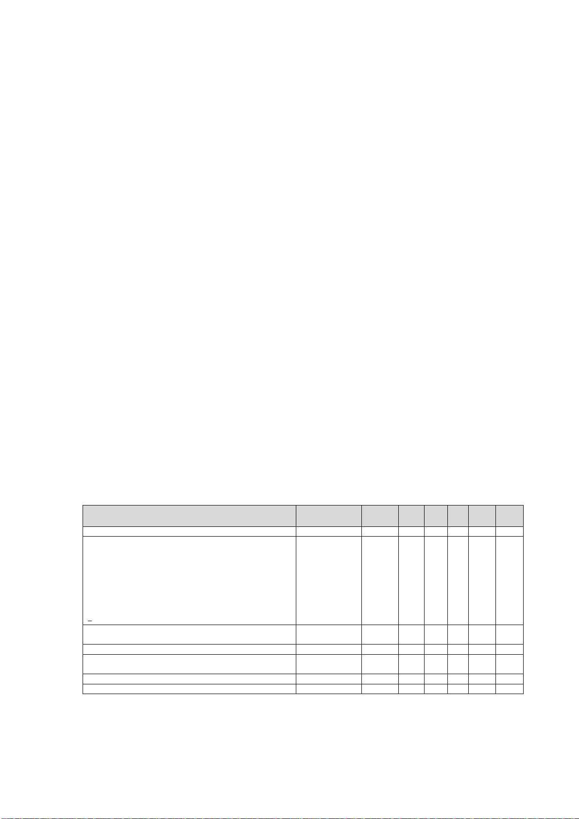
7.1. Checks and periodic maintenance
The user must ensure that periodic maintenance checks are carried out on the respiratory protection device as
defined in the instruction manual provided by the manufacturer.
Operation to carried out
Before release for
use
Prior each
use
After
use
Every 6
month
Every
year
Every 2
year
Every 6
years
Cleaning and disinfection
X
X (1)
Visual inspection:
•Presence of scratches or cracks on the visor
•Visible signs of overheating (2)
•Cuts or cracks on the rubber
•Presence and integrity of the gasket on the threaded
connector
•Presence and integrity of the inhalation and exhalation
valves
•Hand pull the head harness and check integrity
X
X
X
Static seal test in negative pressure (3) and in positive pressure
by the user
X
X
Tightness test with test equipment
X (1)
X
Replacement of inhalation gasket, head harness and other
gaskets
X
Replacement of inhalation and exhalation valves
X
Check of the thread of the connector with plug gage
X
Legenda:
(1) Even in absence of use, unless it has been stored in airtight package.
(2) Only if exposed to heat sources
(3) The test consists in checking that are not noticed leakages through the mask after donning it, closing the inhalation inlet
with the palm of the hand and building a negative pressure by attempting to inhale.

16
7.2. Cleaning
The mask must be cleaned every time it is used. Lack of cleaning, besides hygienic problems, can also jeopardize
the correct functioning of the device. Washing can be performed in a traditional way by dipping in water, or by
ultrasonic washing. In both cases, depending on the need to perform a deep cleaning of the mask due to its
conditions, it can be disassembled and all the components can be cleaned separately.
Il lavaggio a ultrasuoni deve essere svolto con macchinari SONOREX SUPER RK514BH o RK1028CH che possono
essere forniti dalla D.P.I. s.r.l.. L’utilizzo di macchinari diversi può pregiudicare il funzionamento della maschera.
Ultrasonic washing has to be done with SONOREX SUPER RK514BH equipment or RK1028CH which can be
supplied by D.P.I. s.r.l.. Using different equipment can damage the correct functioning of the masks. Ultrasonic
washing temperature must be set at a temperature not higher than 40°C using a mild detergent 5% dilution in
water. Traditional washing can be performed with tepid water and a mild detergent 5% dilution in water. In any
case, never use solvents! After cleaning it thoroughly, rinse under running water and hung up to dry in open air,
avoid in any case exposure to direct solar radiation, or in special cupboards. During drying pay attention not to
expose the mask to direct contact with hot parts or with hot air (warmer than 45°C) or to direct solar radiation
in order to avoid damages to rubber parts. Check that after cleaning operations no traces of detergent are left
otherwise repeat rinsing and drying. If the mask has been disassembled for washing, a leak tightness test with
test equipment has to be performed. If the mask has been exposed to chemicals particularly toxic, biological or
radioactive agents, maintenance has to be performed by specialized personnel or by D.P.I. s.r.l. Maintenance and
Assistance Service.
7.3. Disinfection
Mask disinfection is necessary when it is worn by different users in order to prevent hygienic or sanitary
problems. Disinfection can be performed in a container after cleaning or can be performed by the equipment
SONOREX SUPER RK514BH or RK1028CH which can be supplied by D.P.I. s.r.l.. Keep in mind that detergent and
disinfecting agent neutralize each other when used at the same time, therefore baths have to be kept separate
washing carefully the container among the two. Disinfection can be performed only with authorized detergent
5% diluted in water. At the end rinse in running water and dry with the same precautions as of paragraph 7.2
Warning: for the cleaning and disinfection don’t use solvents (like acetone and alcohol) or abrasive substances.
Follow only the procedure described in the two previous points and use only the indicated detergent and
disinfectants. Detergents, dosages and exposure times other than those indicated, could damage the mask.
The detergents not diluted can cause damages to the user’s health. Then using with care wearing glasses and
gloves.
8. Tightness test with test equipment
In the event the mask has been disassembled in order to be cleaned or to have some component parts replaced,
a tightness test must be carried out. Before carrying out the tightness test, make a visual check. Check valves,
housing and rubber gasket in particular, in order to make sure they are clean. Defective parts must be replaced.
Mask which failed the tightness test cannot be used.
8.1. Test rig
The test equipment consists of an inflatable dummy head, a mouthpiece connector, a test rig, a plug to seal the
exhalation valve and a plug to seal the threaded connector. The test equipment, allows for a negative or positive
pressure test.
8.2. Testing
Place the mask to be tested onto the inflatable head (wetting the surface with water) and tighten the head
harness. Inflate until the head becomes stable and in good contact around the sealing edge of the mask. If
necessary, adjust better the head harness. Place the sealing plug on the inlet threaded connector of the mask.
Follow the test equipment instructions as shown in its instruction manual.
8.3. Leak tightness of mask and exhalation valves
The mask and exhalation valves pass the tightness test when, with the exhalation valve previously damped, after
a 10 mbar (1000 Pa) negative pressure is created inside the mask, the pressure change is not more than 1 mbar
(100 Pa) per minute. If the test is positive, remove the mask from the dummy head and dry it if necessary. The
mask can be used only after passing the tightness test.

17
9. Transport, storage and disposal
The masks must be stored in place at a temperature not higher than 50°C, protected from cold and humidity, the
rays of sun, intense heat, corrosive substances which can damage its rubber, shocks, risk of falling down, dust
and dirt. The thermoplastic parts must not be submitted to prolonged tensions and pressures to avoid distortion.
The masks must be stored in their cases or in special cupboards.
The C700 masks have not to be considered special waste and fall in to the code CER150203 and have to be
disposed taking into account that their main component materials are:
-Rubber and silicon;
-Plastics;
-metal (low quantity).
Particular precautions in compliance with the provisions of the law must be adopted according to their possible
level of contamination, based on their conditions of use, at the time of disposal as in this case they fall within the
CER150202 code.
For transport, use the original packaging.
10. Specific maintenance instructions and replacement of spare parts
When the mask is disassembled in order to be cleaned and disinfected, it has to be reassembled following the
same procedure of spare parts replacement unless differently indicated. Make sure that all component parts are
correctly assembled, paying attention to not damage all component parts during these operations.
10.1. Replacement of Inner mask (Figure 3)
Remove the inner mask from the threaded connector. Take the new inner mask and insert it into the groove of
the threaded connector. Centred it with the alignment between marks in the upper part of the inner mask and
the pin of the threaded connector.
10.2. Replacement of threaded connector (Figure 4)
Remove the half mask from threaded connector body as described in paragraph 10.1. Remove the grid by moving
the tooth top through the insertion of a tool (e.g. a screwdriver of maximum width 4mm and maximum thickness
1mm or equivalent) in the slot of the grid positioned just above the threaded connector and moving the tool
downwards so that the end inside the grid goes upwards disengaging the looking tooth; then release from the
threaded connector body the grid by releasing the tooth lock. Remove the threaded connector body turning its
counterclockwise. Replace OR57X2 on the threaded connector body. Insert the new threaded connector body
and turn it clockwise. Replace the half mask as described in paragraph 10.1. Finally apply the grid until you hear
the other click of the two teeth.
10.3. Replacement of visor (Figure 5)
Loosen the screw on the bottom side of the frame. Remove the frame, then remove the facepiece. Remove the
threaded connector body and the inner mask as described in paragraph 10.1 and 10.2. Replace the facepiece on
the visor. For correct positioning, use the line on the top and on the bottom side of the facepiece and the visor.
Put on the frame in place all around the facepiece: first of all the “T” at the top must be placed, secondly put in
place the bottom of the frame and complete the assembly pulling lateral tie rods. Finally tighten the screw.
Replace the threaded connector body and the half mask as described in paragraph 10.1 and 10.2. Apply the grid
until you hear the two teeth click.
10.4. Replacement of exhalation valve (Figure 6)
Remove the half mask from the threaded connector body. Remove the exhalation valve seat from the threaded
connector body by moving the tooth at the top through the insertion of a tool (e.g. a screwdriver) in the slot of
the exhalation valve seat positioned just above the exhalation valve and turning the tool clockwise disengaging
the locking tooth; then release it from the threaded connector body. Grasp the exhalation valve and pull outward
to release it and then remove it. Insert the stem mounting the new valve in the center hole of the exhalation
valve seat and pull it from the outside until it clicks. Push the exhalation valve seat on the threaded connector
body until it stops and then turn it counterclockwise until you hear the click. Replace the half mask as described
in paragraphs 10.1.
10.5. Replacement inhalation valve (Figure 7)
Remove the half mask and the threaded connector body as described in paragraphs 10.1 and 10.2. Remove the
inhalation valve seat from the threaded connector body pushing the lateral locks through a tool until they click.
Replace the inhalation valve by matching the two holes of inhalation valve with the two pins of inhalation valve

18
seat. Replace it in the threaded connector body by sliding the lateral pins until the double click. Replace the half
mask and the threaded connector body as described in paragraphs 10.1 and 10.2.
11. Reference numbers for orders, spare parts, accessories
Article
Codice
Mask C 701 black with rubber harness
43335000B
Mask C 701 aquamarine with rubber harness
43335000G
Mask C 701 nato green with rubber harness
43335000M
Mask C 701 red with rubber harness
43335000R
Mask C 701 white with rubber harness
43335000W
Mask C 701 orange with rubber harness
43335000O
Mask C 701 black with textile harness
43335001B
Mask C 701 aquamarine with textile harness
43335001G
Mask C 701 nato green with textile harness
43335001M
Mask C 701 red with textile harness
43335001R
Mask C 701 white with textile harness
43335001W
Mask C 701 orange with textile harness
43335001O
Mask C 701 black with rubber harness and treated visor with antiscratch coating
43335010B
Mask C 701 aquamarine with rubber harness and treated visor with antiscratch coating
43335010G
Mask C 701 nato green with rubber harness and treated visor with antiscratch coating
43335010M
Mask C 701 red with rubber harness and treated visor with antiscratch coating
43335010R
Maschera C 701 white with rubber harness and treated visor with antiscratch coating
43335010W
Maschera C 701 orange with rubber harness and treated visor with antiscratch coating
43335010O
Maschera C 701 black with textile harness and treated visor with antiscratch coating
43335011B
Maschera C 701 aquamarine with textile harness and treated visor with antiscratch coating
43335011G
Maschera C 701 nato green with textile harness and treated visor with antiscratch coating
43335011M
Maschera C 701 red with textile harness and treated visor with antiscratch coating
43335011R
Maschera C 701 white with textile harness and treated visor with antiscratch coating
43335011W
Maschera C 701 orange with textile harness and treated visor with antiscratch coating
43335011O
Spare parts
Codice
Head rubber harness complete with buckles
42010305
Harness (only rubber)
42010306
Harness (only textile)
42010307
Buckles for rubber harness
42010308
Visor
42010304
Treated visor with antiscratch coating
42010313
Black frame with screw and nut
42010310B
Aquamarine frame with screw and nut
42010310G
Nato green frame with screw and nut e dado
42010310M
Red frame with screw and nut
42010310R
White frame with screw and nut
42010310W
Orange frame with screw and nut
42010310O
Black protective grid
42010311B
Aquamarine protective grid
42010311G
Nato green protective grid
42010311M
Red protective grid
42010311R
White protective grid
42010311W
Orange protective grid
42010311O
Facepiece
42010302
White Facepiece
42010302W
Inner mask
42010303
White Inner mask
42010303W
Inhalation valves (5 pcs)
42010309
Exhalation valves (5 pcs)
42010135
Accessories
Codice
Washing machine 17 litres/2 masks
44370270
Washing machine 41 litres/6 masks
44370300
Washing machine concentrated aqueous disinfectant
44370730
Anti-scratch protective film for the visor
42010027
Soft carrying case
42010017
Frame for corrective lenses
42010312

19
INHALTSVERZEICHNIS
1. ALLGEMEINE INFORMATIONEN
2. ANGEWANDTE NORMEN, EINSATZBEREICH, WARNHINWEISE
2.1. BESONDERE EINSATZBEDINGUNGEN
3. KENNZEICHNUNG (TYP-UND MODELLÜBERSICHT)
4. WIRKUNGSWEISE
5. BESTANDTEILE DER VOLLMASKE
6. ANLEGEN DER MASKE UND DICHTHEITSKONTROLLE
7. WARTUNG, REINIGUNG UND DESINFEKTION
7.1. INSTANDHALTUNGS-UND PRÜFFRISTEN
7.2. REINIGUNG
7.3. DESINFEKTION
8. DICHTHEITSPRÜFUNGEN
8.1. PRÜFEINRICHTUNG
8.2. PRÜFABLAUF
8.3. DICHTHEIT DER VOLLMASKE UND DES AUSATEMVENTILS
9. TRANSPORT, LAGERUNG UND ENTSORGUNG
10. BESONDERE WARTUNGSHINWEISE UND AUSTAUSCH VON ERSATZTEILEN
10.1.AUSTAUSCH DER INNENMASKE (ABBILDUNG 3)
10.2.AUSTAUSCH DES ANSCHLUSSSTÜCKS (ABBILDUNG 4)
10.3.AUSTAUSCH DER SICHTSCHEIBE (ABBILDUNG 5)
10.4.AUSTAUSCH DES AUSATEMVENTILS (ABBILDUNG 6)
10.5.AUSTAUSCH DES EINATEMVENTILS (ABBILDUNG 7)
11. VOLLMASKEN, ERSATZTEILE UND ZUBEHÖR
FIGURE, FIGURES, ABBILDUNGEN
This manual suits for next models
1
Table of contents
Languages:
Other SEKUR Respiratory Product manuals


