Aerogen Solo User manual

System Instruction Manual
www.aerogen.comwww.aerogen.com


Aerogen®Solo System Instruction Manual
1
Contents
Introduction 2
Indications for Use 2
System Warnings 4
Assembly & Installation 6
Installation For Use With A Ventilator 11
Optimum Use 14
Installation For Use Off-Ventilator 15
Nebulization Modes 19
Functional Test 23
Aerogen Solo Aerosol Flow Rate Calculation 24
Troubleshooting 25
Warranty 27
Life Of Product 27
Specifications 28
Performance 29
Symbols Glossary 31
Appendix 1 32
Appendix 1: EMC Tables 33

Aerogen®
2
Introduction
The Aerogen®Solo System is an iteration of the Aerogen®Pro Nebulizer
System. The indications for use of the Aerogen®Solo Nebulizer System
are given below. The Aerogen®Solo System consists of the Aerogen®Solo
nebulizer and the Aerogen®Pro-X Controller. It is intended for hospital use
only to nebulize physician-prescribed medications for inhalation which are
approved for use with a general purpose nebulizer. The Aerogen®Solo
nebulizer is for single patient use only and the Aerogen®Pro-X Controller
is for re-use.
The Aerogen Solo System is suitable for intermittent and continuous
nebulization of pediatric (29 days or older) and adult patients as described
in this manual.
Indications for Use
The Aerogen Solo Nebulizer System is a portable medical device for single
patient use that is intended to aerosolize physician-prescribed solutions
for inhalation to patients on and off ventilation or other positive pressure
breathing assistance.

Aerogen®Solo System Instruction Manual
3
Aerogen Solo System
The Aerogen Solo System includes the following components:
Figure 1. Aerogen Solo System
1. Aerogen Solo With Plug
2. T-Piece (Adult)*
3. Aerogen Pro-X Controller
4. Controller Cable
5. AC/DC Adapter
6. Universal Mounting Bracket & Equipment Mount Adapter
7. Continuous Nebulization Tube Set*
8. Aerogen®Ultra* and I-Guard™Aerosol Mask
* Pediatric adapters, Continuous Nebulization Tube Set and Aerogen Ultra
are sold separately. Visit www.aerogen.com for full parts list.
1 2 3 4
5 6 7 8

Aerogen®
4
System Warnings
Read and study all instructions before using the Aerogen Solo
System and accessories. Only trained medical personnel should
operate the device.
This is a single patient use device not to be used on more than one patient
to prevent cross infection.
The components and accessories of the Aerogen Solo System, as packaged,
are not sterile.
The components and accessories of the Aerogen Solo System are not
made with natural rubber latex.
Inspect all parts before use, and do not use if any parts are missing,
cracked or damaged. In case of missing parts, malfunction or damage,
contact your sales representative.
Only use physician-prescribed solutions that are approved for use with
a general purpose nebulizer. Consult drug manufacturer’s instructions
regarding suitability for nebulization.
Use only with Aerogen Solo components, connectors and any accessories,
which are specified by Aerogen in this instruction manual.
Do not use beyond defined life (see page 16 for Aerogen Ultra and page
27 for Aerogen Solo System).
Do not use in the presence of flammable substances or flammable
anesthetic mixtures combined with air, oxygen or nitrous oxide.
To avoid the risk of fire, do not use to aerosolize alcohol-based medications,
which can ignite in oxygen-enriched air under high pressure.
Do not autoclave any component or accessory of the Aerogen Solo
System.
Aerogen®Solo System Instruction Manual
5
Do not modify this equipment without the authorization of the manufacturer.
To avoid damage to the nebulizer:
•Do not apply undue pressure to the domed aperture plate in the center
of the nebulizer.
•Do not push out the Aerogen Vibronic®aerosol generator.
•Do not use a syringe with a needle to add medication.
•Do not attempt to clean the nebulizer.
Do not use or store outside of specified environmental conditions.
Federal (US) Law restricts this device to sale by or on the order of a
physician.
Use of the Aerogen Solo and T-piece during the administration of volatile
anesthetics may result in adverse effects on the constituent plastics. Do
not use with volatile anesthetics unless known to be compatible. Aerogen
have determined that, using anesthetic ventilators, the following volatile
anesthetic agents are compatible under the stated conditions below:
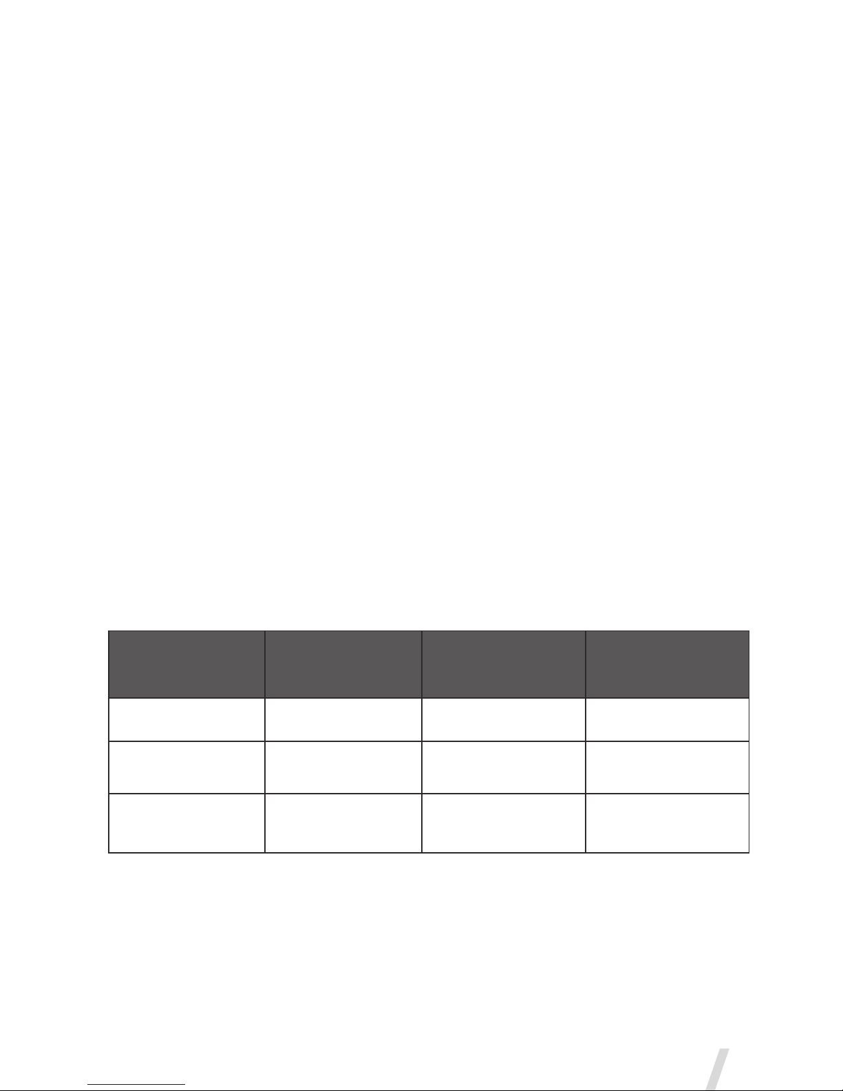
Anesthetic Agent Proprietary Name
Maximum
Percentage of
Anesthetic
Maximum Duration
of Exposure
Isoflurane FORANE®3.5 % 12 hours
Sevoflurane SEVOFLURANE®8 % 12 hours
Desflurane SUPRANE®10 % 12 hours
Aerogen®
6
Assembly & Installation
Aerogen Solo System Set-Up
Perform a functional test of the Aerogen Solo before use as described in
the Functional Test section of this manual (See page 23).
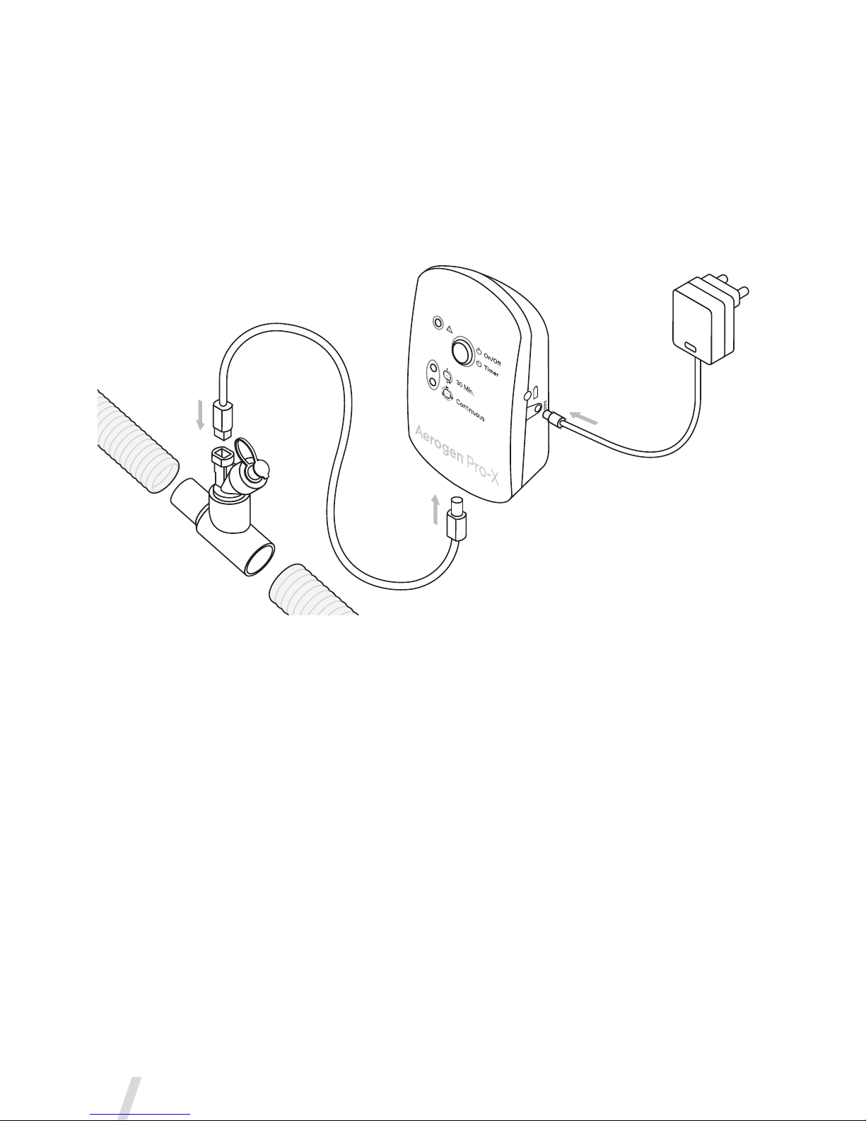
Figure 2. Assembly of Aerogen Solo System
1. Connect the Aerogen Solo to the T-piece by pushing the nebulizer
firmly onto the T-piece.
2. Insert the Aerogen Solo and the T-piece into the breathing circuit.
Note: For use with other accessories, refer to Figure 11, Figure 12 and
Figure 13.
3. Connect the Aerogen Pro-X Controller to the Aerogen Solo using the
nebulizer cable.
4. To operate on AC power (the primary mode of operation), connect the
Aerogen Pro-X AC/DC adapter to the Aerogen Pro-X Controller.
5. Plug the adapter into an AC power source.
Aerogen®Solo System Instruction Manual
7
6. The Aerogen Pro-X Controller can be battery-operated for portable
applications. The rechargeable battery can power the System for up
to 45 minutes when fully charged. In the case of AC power failure the
controller will automatically switch to battery operation.
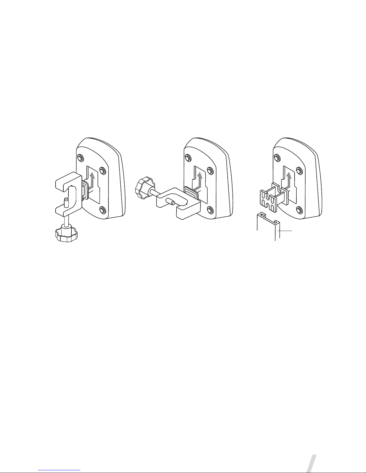
7. Use the universal mounting bracket to attach the controller to an IV
pole or bed rail in either a vertical or horizontal orientation (Figure 3).
8. Where a standard equipment mount is available, use the equipment
mount adapter to support the controller (Figure 3).
Figure 3. Aerogen Pro-X Controller and universal mounting bracket configurations
Warnings
•To ensure uninterrupted operation of the Aerogen Solo, secure both the
AC/DC adapter cable and the controller cable so they cannot become
disconnected during treatment. If clips are available on patient circuits,
run the cables through the eyes of the clips. If clips are not available,
ensure that all cables are routed safely.
•The AC/DC adapter is the means of isolating the Aerogen Solo System
from the mains power supply.
•The continuous mode can only be operated from AC power supply.
•Do not over-tighten knob on the universal mounting bracket.
Vertical
Universal Mounting Bracket
Horizontal
Universal Mounting Bracket
Equipment
Mount Adapter
Standard
Equipment Mount
Aerogen®
8
Aerogen Pro-X Controller
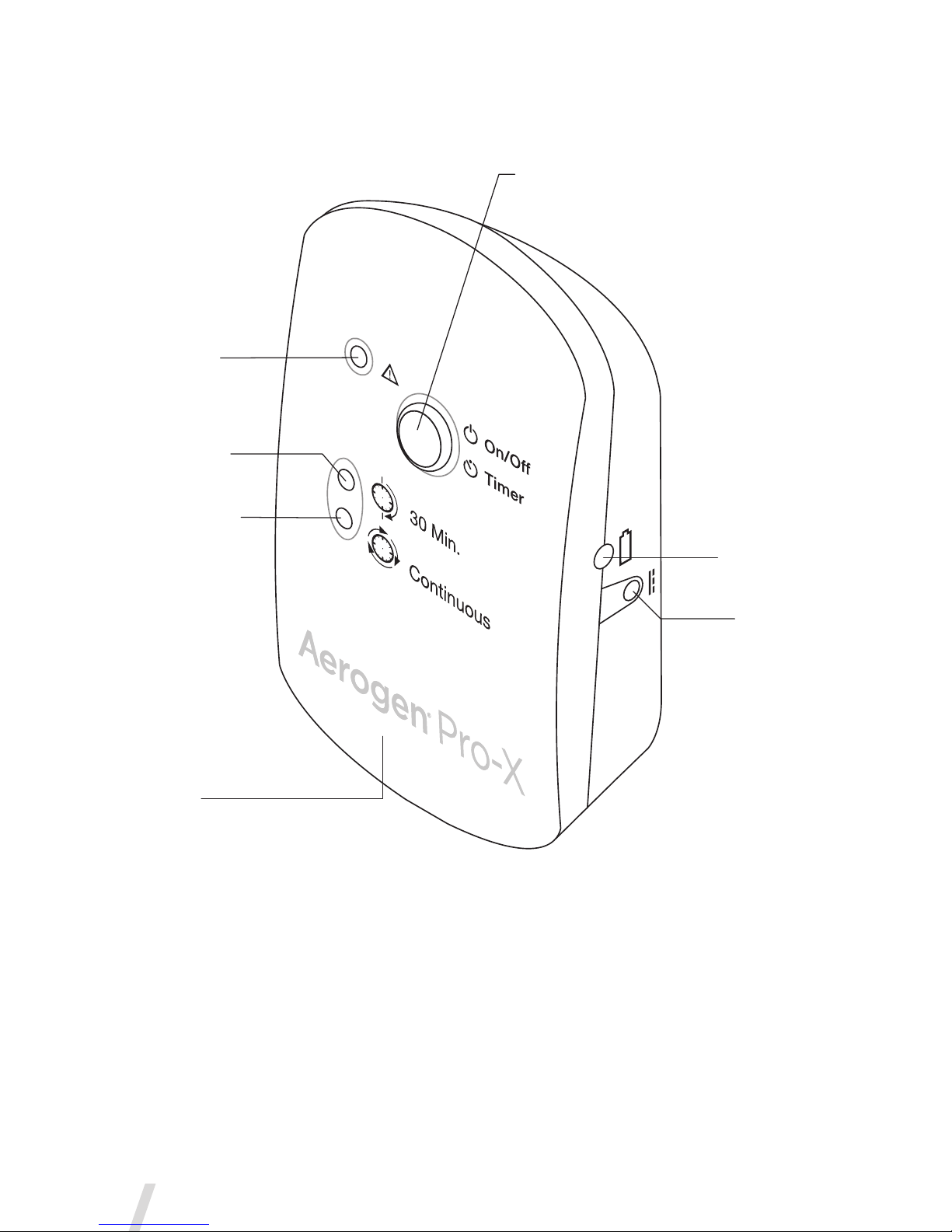
Figure 4. Aerogen Pro-X Controls & Indicators
Controller
Cable Input
Error Indicator
30 Minute Mode
Indicator light
Continuous Mode
Indicator light
On/Off Power
• 30 Min. - Press & Release
• Continuous Mode - 3 Sec. hold from off
Battery Status
Indicator
9V DC Input
Aerogen®Solo System Instruction Manual
9
Table 1. Aerogen Pro-X Controls & Indicators
Control / Indicator Function
30 Min. Indicator
• Green (steadily lit) = 30 Minute
nebulization cycle on
• Green(ashing)=Lowbatterypower
• Nebulizerautomaticallypowersoffafter
30 minutes have elapsed
Continuous Indicator
• Green (steadily lit) = Continuous
nebulization cycle on
• Nebulizerdoesnotpoweroff
automatically
Error Indicator
• Amber (steadily lit) = Aerogen Solo
nebulizer disconnected from Aerogen
Pro-X Controller
• Amber (flashing) = Aerogen Pro-X drive
voltage error
On/OffPowerButton
• To operate in 30 Minute Mode, press the
On/Off button once
• To operate in Continuous Mode, press
and hold the On/Off button for greater
than 3 seconds from off
• Pressing during nebulization turns off
powertothenebulizer
BatteryStatus
Indicator
• Green=Batteryfullycharged
• Amber=Batterycharging
• Nolight=Batteryinoperation
RechargingtheBattery
To recharge the battery, connect the AC/DC adapter to the controller and
connect to AC power source. The battery status indicator is amber while
charging and green when fully charged.
If the controller is placed in long-term storage, it is recommended that the
battery be recharged every 3 months.
Allow a minimum of four hours for the internal battery to fully recharge.

Aerogen®
10
Cleaning the Aerogen Pro-X Controller
Cleaning of controller and controller cable, AC/DC adapter and mounting
brackets:
1. Wipe clean with an alcohol based disinfectant wipe or a quaternary
ammonium compound based disinfectant wipe.
2. Check for exposed wiring, damaged connectors, or other defects and
replace controller if any are visible.
3. Visually inspect for damage and replace the controller if any damage
is observed.
Warnings
•Do not immerse or autoclave the Aerogen Pro-X Controller, cable or
AC/DC adapter.
•Do not place the Aerogen Pro-X Controller in an incubator during use.
•Do not use abrasive or sharp tools.
•Do not spray liquid directly onto the controller.
•Do not wrap the nebulizer cable tightly around any of the system
components.
•Do not use in the presence of devices generating high electromagnetic
fields such as magnetic resonance imaging (MRI) equipment.
•The Aerogen Pro-X Controller contains a nickel metal hydride (NiMH)
rechargeable battery, which should be disposed of in accordance with
local governing regulations at the end of its useful life.
•Follow local laws and recycling plans regarding disposal or recycling of
components, batteries and packaging.
Aerogen®Solo System Instruction Manual
11
Installation for use with a Ventilator
T-Pieces-ConnectiontoaBreathingCircuit
1. For 22mm adult breathing circuits connect the nebulizer with adult
T-piece into the inspiratory limb of the breathing circuit before the
patient Y (Figure 5).
Figure 5. Connecting the Aerogen Solo to a breathing circuit
Note: Figure 5 shows adult configuration only
For 15mm pediatric breathing circuits connect the nebulizer with
the pediatric T-piece into the inspiratory limb of the breathing circuit
before the patient Y.
The Aerogen Solo can connect to 10mm pediatric breathing circuits
with the 15mm pediatric T-piece and the pediatric adapters. This can
be positioned approximately 30cm (12 in.) back from the patient Y
(Figure 6).
Figure 6. Connecting to a pediatric breathing circuit

Aerogen®
12
2. The Aerogen Solo can be placed on the dry side of the humidifier as
shown in Figure 7. The Aerogen Solo can be used with a nasal interface
in this configuration.
Figure 7. Aerogen Solo on dry side of humidifier
3. The Aerogen Solo can be placed between the wye and endotracheal
tube as shown in Figure 8. The Aerogen Solo can be used with a Heat
and Moisture Exchange Device (HME) which may contain a filter.
Figure 8. The Aerogen Solo placed between the wye and endotracheal tube.
4. Only a HME approved for use with a nebulizer should be used in this
configuration (Figure 9). Follow the HME manufacturer instructions
regarding use with a nebulizer. Ensure the combination of nebulizer,
T-piece and HME volumes is suitable for the tidal volume being
delivered. See Table 3 for T-piece volumes.
Figure 9. The Aerogen Solo placed between the HME and endotracheal
tube.
5. Follow ventilator manufacturer instructions for performing a leak test
after inserting or removing the nebulizer.
Warnings
• Only use with HME devices whose manufacturer’s instructions allow
use with a nebulizer, and always follow the HME manufacturer’s
instructions.
• Ensure that the total combined volume of nebulizer, T-piece and HME
is suitable for the tidal volume being delivered and does not increase
dead space to the extent that it adversely impacts the ventilatory
parameters of the patient.
Aerogen®Solo System Instruction Manual
13
4. Only a HME approved for use with a nebulizer should be used in this
configuration (Figure 9). Follow the HME manufacturer instructions
regarding use with a nebulizer. Ensure the combination of nebulizer,
T-piece and HME volumes is suitable for the tidal volume being
delivered. See Table 3 for T-piece volumes.
Figure 9. The Aerogen Solo placed between the HME and endotracheal
tube.
5. Follow ventilator manufacturer instructions for performing a leak test
after inserting or removing the nebulizer.
Warnings
• Only use with HME devices whose manufacturer’s instructions allow
use with a nebulizer, and always follow the HME manufacturer’s
instructions.
• Ensure that the total combined volume of nebulizer, T-piece and HME
is suitable for the tidal volume being delivered and does not increase
dead space to the extent that it adversely impacts the ventilatory
parameters of the patient.
Aerogen®
14
• Always monitor the resistance to flow and excessive rain-out and
change the HME device as per manufacturer’s instructions.
• Do not use a filter or heat-moisture exchanger (HME) between the
nebulizer and patient airway.
• Condensate can collect and occlude ventilator circuits. Always position
ventilator circuits so that fluid condensate drains away from the patient.
• Always connect a bacteria filter to the expiratory inlet of the ventilator.
Otherwise the function of the expiratory channel may be degraded.
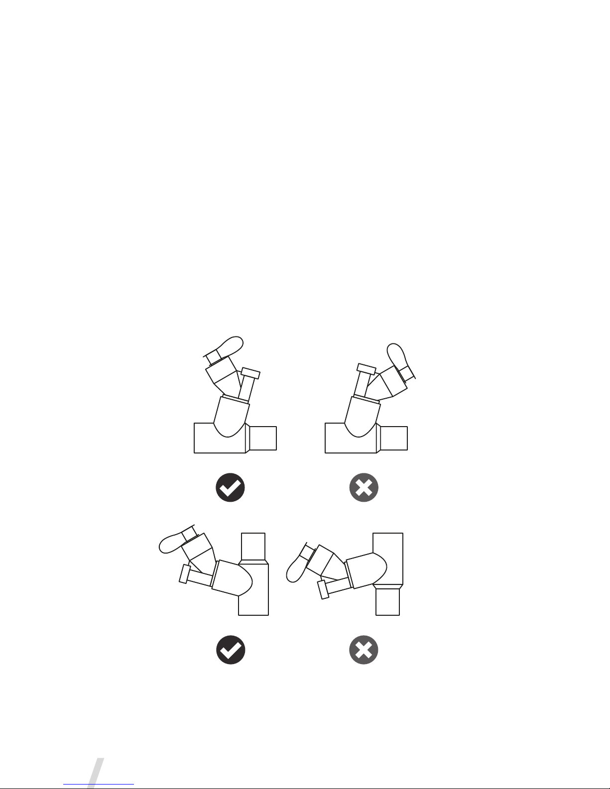
Optimum Use
For optimum use of the Aerogen Solo, ensure it is correctly orientated as
shown in Figure 8. This applies to both 30 Minute and Continuous modes.
Figure 10. Optimum Use of the Aerogen Solo
Aerogen®Solo System Instruction Manual
15
Installation for use Off-Ventilator
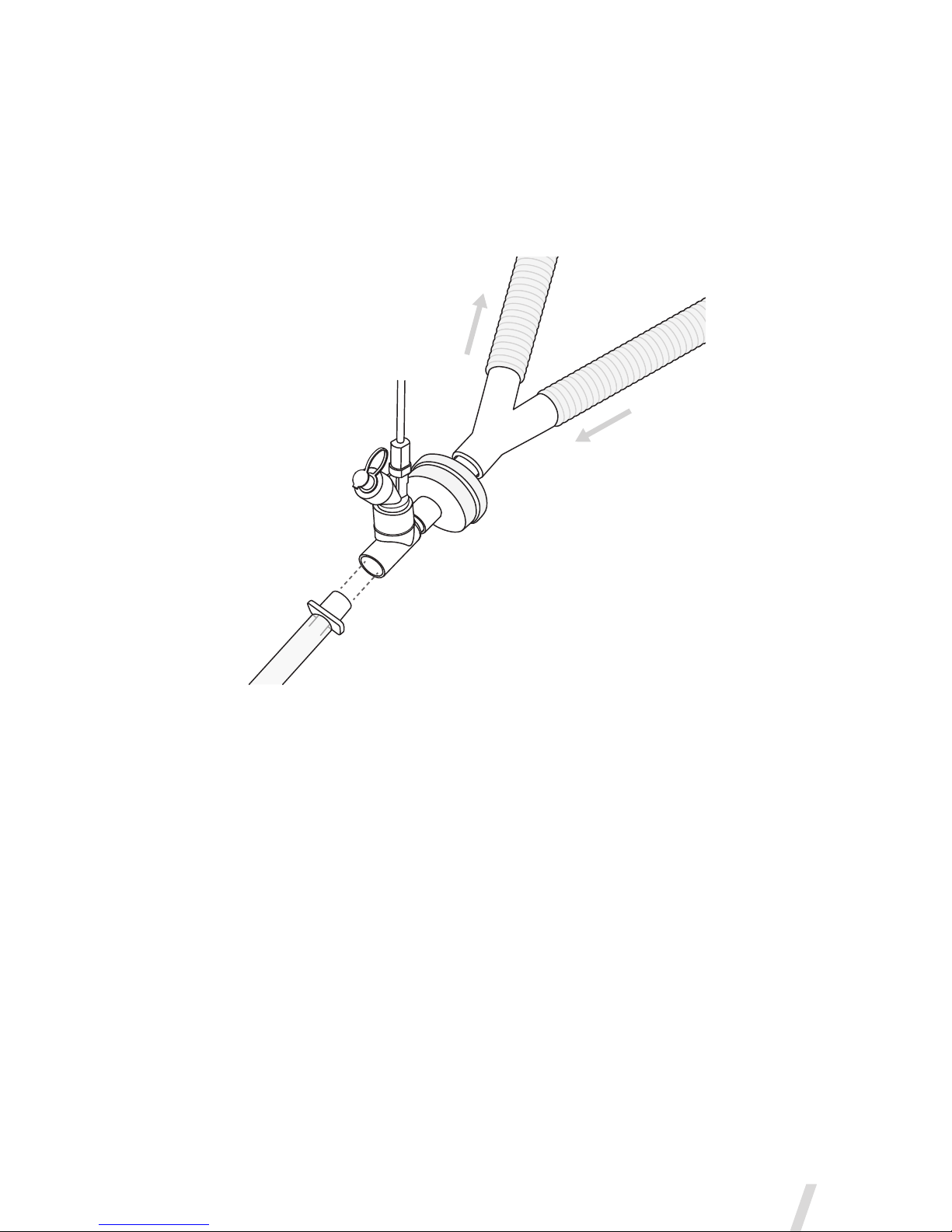
UsewithaFaceMask
Mask kits, which include a vented elbow and mask elbow, are available
separately (visit www.aerogen.com for full parts list).
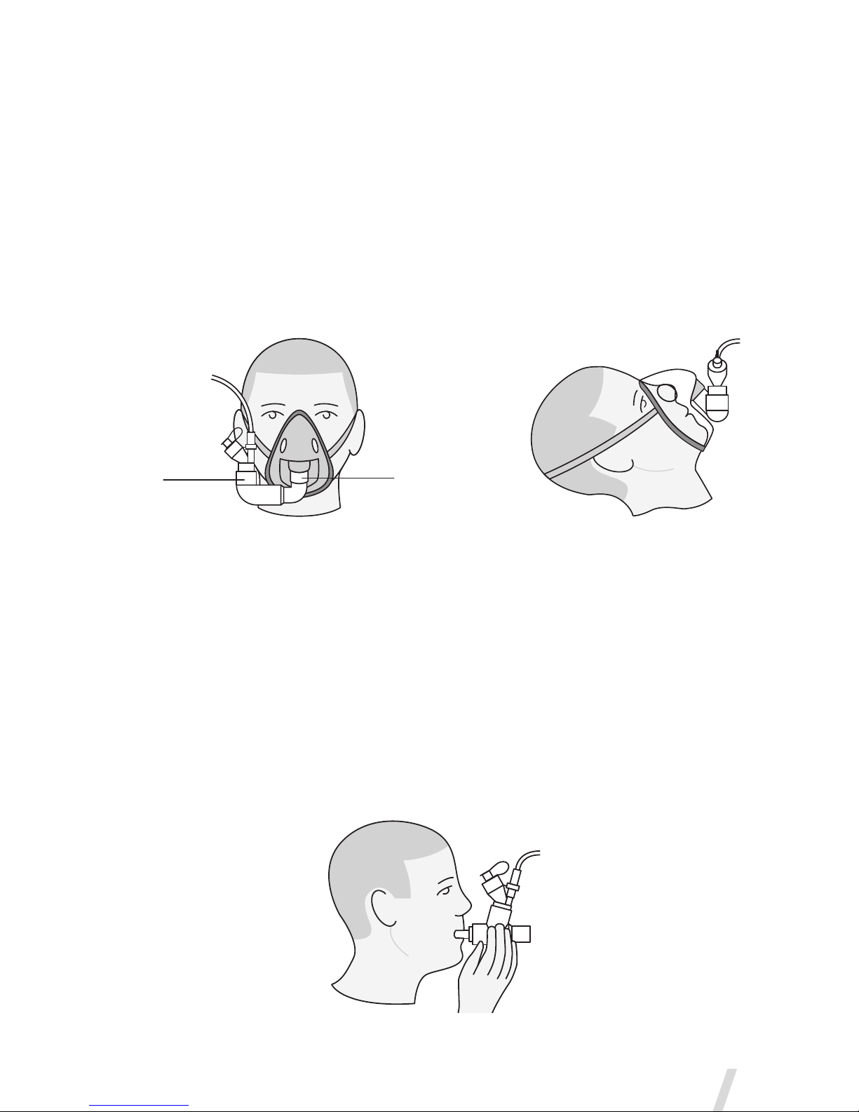
1. When using a mask, connect the vented elbow, mask elbow and mask
to the nebulizer by firmly pushing the parts together.
2. Rotate the vented elbow to suit the position of the patient (Figure 11).
Figure 11. Connecting to a mask
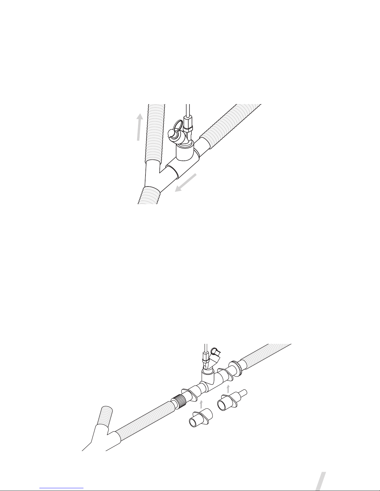
UsewithaMouthpiece
The Aerogen Solo is compatible with any standard ISO 22mm nebulizer
mouthpiece inserted into the adult T-piece.
When using a mouthpiece, connect the nebulizer to the T-piece and
then connect the T-piece to the mouthpiece by pushing the parts firmly
together as shown in Figure 12.
Figure 12. Connecting to a mouthpiece
Patient Upright
Patient Reclined
Face Mask
Elbow
Vented
Elbow
Patient Upright
Patient Reclined
Face Mask
Elbow
Vented
Elbow

Aerogen®
16
Warning: To ensure correct nebulization, maintain the nebulizer in a
vertical orientation (Figure 11 & Figure 12).
UsewithaNasalInterface
The Aerogen Solo can be used on/off ventilator with a nasal interface
when configured with a humidifier (Figure 7).
Aerogen Ultra
The Aerogen Ultra is an accessory specific to the Aerogen Solo nebulizer.
It facilitates intermittent and continuous nebulization and optional supply
of supplemental oxygen to pediatric (29 days or older) and adult patients
in hospital use environments via mouthpiece or aerosol face mask. If
supplemental oxygen is used, for pediatric patients under 18 years of age,
a maximum flow rate of 2 LPM should be used.
Note: The mouthpiece should not be used for children under 5 years of
age.
Figure 13. Assembly of Aerogen Ultra
Oxygen Tubing
Face Mask
Aerogen Solo
Mouthpiece
Aerogen Ultra

Aerogen®Solo System Instruction Manual
17
The Aerogen Ultra is a single patient use device with a validated defined
life of:
•In intermittent use for a maximum of 20 treatments; which is based
upon a typical usage profile of four 3 mL doses per day over 5 days,
with an average treatment time of 9 minutes.
or
•In continuous use, for a maximum of 3 hours.
The Aerogen Ultra can be used in conjunction with the Aerogen Solo
Continuous Nebulization Tube Set (see page 20).
Optimal aerosol delivery is achieved with valved mouthpiece or valved
face mask (as supplied) with low/no oxygen flow.
Inspect for device integrity and correct valve placement prior to use.
1. Insert Aerogen Solo nebulizer firmly into Aerogen Ultra in orientation
shown in Figure 11.
2. If supplemental oxygen is required, firmly attach oxygen tubing to
Aerogen Ultra.
Note: Oxygen flow rate should be set between 1-6 LPM for adult and
a maximum of 2 LPM for pediatric patients less than 18 years of age.
3. If an aerosol face mask is required, remove mouthpiece and attach the
aerosol face mask to Aerogen Ultra.
Note: When using an aerosol face mask, a minimum oxygen flow of 1
LPM is required.
4. Add medication to nebulizer.
5. Connect cable to Aerogen Solo and power on controller.
6. Introduce Aerogen Ultra to patient and observe aerosol flow to ensure
correct operation.
7. Remove excess rainout from the Aerogen Ultra periodically (hourly with
continuous nebulization).
8. To ensure optimum performance of the Aerogen Ultra, remove any
residue by rinsing through with sterile water, shake off excess and allow
to air dry.

Aerogen®
18
Warnings
•Do not use with a closed face mask or a standard oxygen mask.
•When using with an aerosol face mask, always use supplemental
oxygen flow of 1-6 LPM for adult and a maximum of 2 LPM for pediatric
patients less than 18 years of age.
•Performance of the Aerogen Ultra may vary depending upon the type
of drug and Aerogen Ultra configuration used.
•Do not exceed recommended oxygen flow for system.
•Ensure oxygen connection port or tubing is not occluded.
•Do not use the Aerogen Ultra without a mouthpiece or face mask.
•Visually check Aerogen Ultra post-rinsing to ensure that valves have
not become dislodged.
•Do not cover Aerogen Ultra valves during use.
•Do not use Aerogen Ultra in conjunction with the Aerogen Pro nebulizer.
•Do not autoclave any component of the kit.
•Ensure tubing is safely orientated to prevent strangulation hazard.
Other manuals for Solo
4
Table of contents
Other Aerogen Respiratory Product manuals


