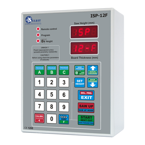
Selbit ISP - 010 User manual

MANUAL HANDBOOK
Automatic thickness controller for sawing frame machines
Automatic thickness controller ISP
machine.
Before assembly and start please read this handbook manual carefully, instructions
provided help you in correct mounting and operating of our product.
MANUAL HANDBOOK
Automatic thickness controller for sawing frame machines
ISP - 010
Automatic thickness controller ISP
-
010 is designed to be mounted on the sawing frame
Before assembly and start please read this handbook manual carefully, instructions
provided help you in correct mounting and operating of our product.
Automatic thickness controller for sawing frame machines
010 is designed to be mounted on the sawing frame
Before assembly and start please read this handbook manual carefully, instructions

www.selbit.pl
- 2 -
Content:
Chapter 1 – Mounting and connections
Chapter 2 - First start
Chapter 3 – Checking controller’s parameters
Chapter 4 – Quick access buttons A, B, C
Chapter 5 – Normal mode cutting (board after board)
Chapter 6 – Normal mode cutting without board taking out
Chapter 7 – Manual mode cutting (manual program)
Chapter 8 – Automatic saw mode (quickprogram)
Chapter 9 – Program saw mode (A, B, C)
Chapter 10 - Operating order
Chapter 11 – EMC Approval
Chapter 12 – Possible errors and solutions
CHAPTER 1
Mounting and controller’s connections
During controller’s mounting is advised to follow this instructions correctly.
Point - 1
Before mounting in the main board (fig. 1) please cut off rectangle hole 175 x 140 mm.
This hole should be made carefully thus rubber sealing is adjoined to the from panel.
Eventually any irregularity created after incorrect cutting out please smooth them using small
metal file and protect it by anti-corrosion painting. If on the main panel is no place to mount
controller, it is possible to add it as separate device (fig. 2).
Figure 1. Controller mounting on the main board. Figure 2. Mounted controller as separate device.
In case of controller mounting as a

www.selbit.pl
- 3 -
separate device it is possible after its assembly to attached it to the machine’s frame
using 4 added screws for this purpose. In another case please made special fixing for
mounting the controller which can be used as a distance support as well (fig. 2, E element).
Electric montage
CAUTION !
During electrical assembly there is a possibility of a electric shock thus all actions
should be made while electric power is off. For this purpose please turn off machine’s
main electric switch!!!
All cable connections should be made using special wires with double insulation
oriented for use of the electric devices powered by 230V alternating current. Cables
should be rounded with diameter suitable into holes in the controller back casing
accordingly. Tips of the cables should be cleaned and special quill should be used or
tips should be covered by thin tin layer. Please follow this instructions very carefully
especially electric connections should be made according to provided instructions. It is
required for correct and failure-free controller operating.
Machine where the controller is mounted should be equipped in well working head saw
ending switchers and contactors of the up and down feeding should be protected to be
on at the same time !!!
Point - 2
Power transformer TSS-8/001 assembly
In power cubicle added power transformer
TSS-8/001 needs to be mounted. Mounting is designed for well known and used holding bus
TSS-35. Please place the transformer as far as possible from other electrical elements ( e.g.
frequency changer, contactors, other transformers). It is important because of the
electromagnetic interference which may disturbing controller’s electronics. Please connect to
the connections marked as PRI power supply of 230V. For power supply please choose this
phase of electric supply of the machine which is not connected to the any inductions coils,
contactors or inverters. 230V supply cables should be placed as far as it is possible form other
cables in the power cubicle. To the transformer’s clips marked as SEC 12V please connect
wires which feed electronic plate of the controller. Analogically please place this wires as far
as it is possible from other power cables, especially from 230V which powered the
transformer. Length of the cables (12V) should be chosen accordingly to the place where the
controller is mounted.
Point – 3 Choke CPZ mounting
Anti-disturbance choke CPZ (WX1P 224M 440V)
added in the controller kit is designed to
protect from any other electromagnetic disturbance made by other electrical devices mounted
on the frame machine saw. Its correct mounting is decisive for correct controller operating.

www.selbit.pl
- 4 -
Those CPZ outputs should connected in parallel to the contactors’ coil. CPZ should be
connected with contactor’s coil of the down feeding, up feeding and barker contactor
separately (if the sawing frame machine is equipped with barker).
Fig. 3 Choke CPZ constructions and connections
Point -4
Rotating encoder mounting
Added rotating encoder is designed to convert rotation of the head saw feeding screw for
electrical impulses. Number of the impulses depends on screw pitch and this relation
describes table 1. In most of the frame sawing machines this screw has got free tip where the
encoder can be installed. Please make a concentric hole in the screw and mount encoder’s
clutch. Please make sure that this hole is concentric otherwise it can cause swinging and
eventually incorrect encoder working and its damage. Please make hole around 15 mm and
create thread M8. Next mount encoder using fixing band (fig.4). The band should be attached
to the special fixing which because of the variety of the frame sawing machines should be
created individually. Example of the encoder mounting is shown at the photo 4a below.
Photo 4a. Example of the necoder mounting. Fig. 4 Encoder mounting ex ample.

www.selbit.pl
- 5 -
Table 1
Screw pitch
[mm./obr.] Encoder type
[imp./rotation] Devider
3 Rotating 42 28
4 Rotating 42 21
5 Rotating 50 20
6 Rotating 48 16
7 Rotating 42 12
8 Rotating 48 12
9
Linear MSK320 + MB3200
5
10 Rotating 50 10
Chain sawing frame machine Linear MSK 320 + MB 320
5
Data from table 1 should be used during procedure of checking the controller’s
parameters.
Cable connection of the encoder should be routed as far as it is possible from other electrical
cables. Using special clip bands lead it to the place where the controller is mounted.
Point – 5
Linear magnetic encoder mounting
(version for chain sawing frame machines)
In case of saw head fed with chain the linear magnetic encoder MSK-3200 needs to be used.
It works together with magnetic tape MB-3200.
The magnetic tape contains two parts which contains with self-adhesive layer. First,
thicker part please place on the smooth and flatten surface (please clean the surface carefully
before sticking the tape using acetone or spirit). During sticking please get unstuck only small
part of the tape on the tip and stick it to the surface. Next get unstuck rest of the tape slowly
sticking it to the surface simultaneously. During sticking please use rubber roll to create
bigger adhesive pressure. Please stick the tape very careful and try to not create any air
bulging and notice to stick it straight. Next please stick the second part of the magnetic tape –
steel protection strip using the same proceeding as above. Both tapes should be stuck in one
line laying on each other creating two layers. Sensor MSK-3200 should be mounted on not
moveable part of the machine (according to the controller) to not create any cable movements
which can cause its damage. In case of mounting sensor on moveable part please protect cable
from its non-controlled damage leading it in a special portable buses. Sensor should be
mounted with two screws in a way that the magnetic tape should be in a 1 to 1,5 mm distance
and in parallel with it. Please notice during leading the cable to place it as far as it is possible
from other cables. Please do not place any sources of the magnetic field next to the magnetic
tape during, before and after mounting. It may cause it serious damage and incorrect working
of the controller. Please clean the surface of the tape from time to time with sift brush.
Please do not hit senor or the tape. The sensor should be mounted in that way thus text
SCALE SLIDE is faced on the magnetic tape side. The sensor and the tape should be mounted
in a such way that during feeding sensor “is above” the tape in all range. Please notice the
stability of the tape and the sensor during normal operating.

Fig. 5 Sensor and magnetic tape mounting example
Point – 6
Head saw steering outputs connection
Sawing frame machine where the controller is mounted should be equipped with
head saw up and down feeding contactors ( relays). Contactors steering should be connected
in a such way that it is impossible to work them both in the same time (connecting
contactors cause disconnecting of the other). To create such a way of connection please use
ancillary contactors and connect them according to the diagram below.
www.selbit.pl
- 6 -
Fig. 5 Sensor and magnetic tape mounting example
Head saw steering outputs connection
Sawing frame machine where the controller is mounted should be equipped with
head saw up and down feeding contactors ( relays). Contactors steering should be connected
in a such way that it is impossible to work them both in the same time (connecting
contactors cause disconnecting of the other). To create such a way of connection please use
ancillary contactors and connect them according to the diagram below.
Sawing frame machine where the controller is mounted should be equipped with
head saw up and down feeding contactors ( relays). Contactors steering should be connected
in a such way that it is impossible to work them both in the same time (connecting
of one
contactors cause disconnecting of the other). To create such a way of connection please use

www.selbit.pl
- 7 -
Fig. 6 Contactors and ancillary contacts connection diagram.
Contactors steering cables connection
Head saw up and down feeding buttons which sawing frame machines contains
should be without holding shot-circuit type (that cause of their contact only while pressing,
when there is no press they should be disconnected). Please connect above buttons using cable
which contains two pairs of wires in doubled round insulation with proper diameter to lead
them through bigger of the hole in the back casing of the controller. One pair of the wires
please connect in parallel with up head saw feeding button (fig. 7 ) and the second one with
down head saw feeding button. Please use special clip or tined the tips of the wires. Please use
also different wire colors which helps you in easy identification during connection with the
controller’s electronics main plate. Place the cable as far as it is possible from other wires and
lead them in the place of controller’s mounting.
Fig. 7 Contactors steering cables diagram connections
There is a possibility to connect contactors steering cables direct to the contactors thus
to meet original connection configurations but instructions given above provide simpler
solution.

www.selbit.pl
- 8 -
Point – 7
Prepared cables connections and casing assembly of the controller.
After creation of the all required connections next step is to connect them with the
controller’s main plate.
In the back casing please screw in two PG chokes facing nuts from the inside. Please lead
through mounted chokes follows cables:
-through the biggest one, wires of the head saw contactors steering (two pairs of the cables
from steering buttons)
-though middle one, cable of the rotating encoder
-though choke which is the nearest of the casing middle, power cable 12 V (connection
SEC 12 V from the transformer TSS8/001).
Please connect power cable 12 V (with prepared cables’ tips) to the junction marked as 12
V on the controller’s main plate.
Contactors steering wires connect with junctions on the controller’s main plate as follow:
-no. 1 pair of cables of the down feeding with junction marked as DWN
-no. 2 pair of the up feeding with junction marked as UP.
Rotating encoder’s connection:
Encoder cables please connect with junctions marked ENCODER as follow:
-brown cable with (+) plus controller’s connection
-blue cable with (-) minus controller’s connection
-white cable with IN-1 connection
-black cable with IN-2 connection.
Magnetic encoder’s connection MSK-320 in chain sawing frame machine:
Magnetic encoder cables please connect with junctions marked ENCODER as follow:
-brown cable of MSK-320 with controller’s junction marked as (+) plus
-black cable of MSK-320 with controller’s junction marked as (-) minus
-red cable of MSK-320 with controller’s junction marked as IN-1
-orange cable of MSK-320 with controller’s junction marked as IN-2

www.selbit.pl
- 9 -
CAUTION!!!
Incorrect connection of the rotating or magnetic encoder may cause its serious damage!!
Next step after creating all of the connections is assembly of the controller’s casing. Before
connecting from panel with the back side please check if the rubber sealing is in the special
groove. It is important in regarding sealing and protecting controller’s main electronic plate
from any contamination. After put the from panel in together with the back side please screw
casing using included six screws 4,1x12. Before mounting the controller on the machine it is
recommended to checking of proper controller’s operating according to “first start” chapter
(2). After checking of the controller’s proper operating please use safety plugs in the places
where screws are and mount the controller on the machine. Controller’s mounting in the main
machine’s board is analogical, there is only one difference that front panel is screwed from
the inside with plastic frame and main panel casing. After all mounting please carefully pull
out cables which go out at the back side of the controller’s casing to reduce their unnecessary
length in the inside. Please be careful to not destroy any connection. After this operation
please screw PG choke to create proper sealing. Next step, in case the controller as a separate
devise, please mount it using four 4,1x10 screws on the sawing frame machine. Screws should
go though four holes in the back casing created for this purpose.
CHAPTER 2
First start
Controller’s connections checking
To check correctness of the controller’s connections, please follow the instruction below:
-after turning on please notice text ISP 010 on the display. If the text is doesn’t show
please check connections of the transformer TSS8/001 and try again.
-next after the sign disappear, please press head saw up feeding button placed on the main
panel. During manual up or down feeding, please notice if the saw height on the display
changes accordingly. During down feeding, the value should decrease and while up
feeding should increase. If this operation brings false result, that means the value of the
saw height increase during down feeding or decrease while up feeding, please switch the
connections of the encoder. In case of the rotating encoder, please exchange black with
white cable and in case of the magnetic encoder MSK-320 red with orange cable (
ENCODER junction, In1, In2). Next check values displaying once again. This operation is
really important, if saw height counting goes wrongly, it may cause incorrect controller’s
working.
-after above operation, please press 8 button on the “Board Thickness” panel and the
number 8 should be displayed. Now press “Start/Next Cut” button and the controller
should move the head saw a little bit down. If this movement is up, please check the
connections with up and down feeding and it is required exchange junctions DWN with

www.selbit.pl
- 10 -
UP. Analogically it is important to check this connections and create a proper working.
Otherwise it may cause incorrect controller’s operating.
If above checking instructions are correct please follow next step – controller's starting
CHAPTER 3
Controller’s parameters checking
To use those instructions it is required to check pitch of the feeding screw. Please measure it
and write it down below:
Pitch screw in this machine is ……………. Mm
Next, please check type of the encoder mounted on this machine at the end of the screw
(photo 4a). Encoder’s type is marked on its casing and shows impulses to rotation ratio
generating. Please note this number below:
Encoder’s impulses to rotation ratio mounted on this machine is ………… imp/rot.
Next, using table 1 from point 4 of this instruction check which divider is correct for this
sawing frame machine. Example: for pitch screw 7 mm and encoder’s impulses to rotation
ratio 42 imp/rot. divider read from the table is 12.
After checking this values please note it below:
Divider (table 1) …………………
If the controller is mounted on the chain sawing frame machine thus divider according
to the table 1 is 5.
For checking all controller’s parameters, please follow points 1…5 below.
1- Input divider checking
For checking input divider value please turn on the controller and during the ISP 010 is
displayed please press “Clibr.” button. The controller display in “Board Thickness” window
divider symbol at the left side and its value at the right one. Please compare read value with
value which should be provided from the table 1. If the value is not correct, please type in
required one and save it to the controller’s memory pressing “Start/Next Cut” button. Text
“Save” should be shown.

www.selbit.pl
- 11 -
Please notice that after setting up the input divider it is needed to
follow next starting instructions otherwise the controller will not
work properly.
2 – Saw trace value checking
To check and eventually change the value of the saw trace please hold for 3 seconds
button with saw symbol. The symbol of the saw trace and its value will be displayed. Now
there is a possibility to check and eventually change this value depends on the saw type used.
Typing in the saw trace please notice that the value is round off to one place after the come.
Example: if you want to type 2 mm first press 2 button and then 0. On the screen 2.0 value
will be displayed. After checking and eventually changing the value of the saw trace to save it
to the controller’s memory pressing “Start/Next Cut” button. Text “Save” should be shown.
3 – Auto-calibration (controller’s checking in with technical parameters of the sawing
frame machine where its mounted)

www.selbit.pl
- 12 -
Please set up manually saw height around 200 mm above the track level and next
press and hold for 3 seconds “Clibr.” button. The text “AutoCall” will displayed and next
please check if is save to start the head saw in automatic movement of auto-calibration. If
starting the head saw is safe and not hurt anyone please press “Calibr. ” button. Controller
make 4 movements of the head saw down and 9 up.
Next, with “End Call” displayed controller will show end of the calibration and break power
do the head saw. Because of the changes of the sawing frame machine’s mechanical
parameters which depend on variety of factors such as temperature,
frictions factors etc. it is recommended to use auto-calibration at least
twice a week.
4 – real saw height settings
Please check if the mechanical scale (millimeter scaled strip with saw height indicate
needle) is scaled correctly, thus shows real head saw height above the main track of the
machine. It will help with checking rest of the parameters later on.
Correct height indicator is important for correct controller’s calibration.
When the indicator is scaled correctly please set up manually full millimeter value of
the head saw, read it correctly and save it into controller’s memory as follow:
Press and hold “Set Height” button for 3 seconds and on the upper display dashes will
be displayed. Next please type in the read actual saw height value using numeric keyboard.
Please type the value briskly because with longer pause controller end this operation. If there

www.selbit.pl
- 13 -
will be a mistyping in providing the real value, please wait 3 seconds and start again. Please
type in value as follow: e.g. for giving 125 mm press 1-2-5 buttons. Next please storage the
parameter shortly pressing “Start/Next Cut”. The save sign will confirm operation.
5 – Backward feeding saw height settings in Saw UP function
There is a possibility to program two separate modes of the backward feeding saw height
above cut material which are available during cutting, using UP and LO or HI mode buttons.
In normal mode (LO) after pressing UP button, controller rise up the head saw for about 12
mm above cut material. In this mode there is a need to take out cut material before going back
on the track’s beginning with saw head.
In the second available mode (HI), controller rise up the head saw for about 12 mm plus value
of the just cut material. In this mode after cutting there is no need to take out cut material
before going back with the head saw on the beginning of the track.
Standard the controller operates in normal mode (LO).
To check or change mode please follow:
-reboot the controller for about 3 seconds
-when ISP-010 is displayed, please press and hole for about 3 seconds “Saw UP” button.
-on the upper scren the actual mode is show. LO text means normal mode where controller
feed up the head Saw for about 12 mm. “HI” says that controller operate in “Saw Up”
mode and it feed up the head saw for about 12 mm plus last cut value.
-To change modes, please use arrow buttons.
-
Please save mode with “Start/Next Cut” button.

www.selbit.pl
- 14 -
After correct checking of all parameters described above, the controller is ready to use.
If there are any other reasons of controller’s incorrect operating, please refer to chapter
12: “Possible errors and solutions”.
Controller’s practical use
Controller takes into account trace of the saw, cutting thickness displayed on the
screen is real cutting value of produced material. Next instructions describes cutting
methods available in this controller.
CHAPTER 4
Desired cutting values under A, B, C buttons
On the controller’s panel there are three A, B, C buttons available. Please press one of them
shortly and there is a possibility to storage cutting value under each those buttons.
To storage often use cutting value in one of the button follow:
-reboot the controller
-while ISP-010 is displaying press one of the A, B, C button and there will be Abc text and
dashes shown on the screen
-next, please press again one of the button where the value will be saved, name of the value
is shown (A, B or C)
-type in the value and eventually press next button to store next cutting value
-After desired values save them using “Start/Next Cut button”. “Save” confirm operation.

www.selbit.pl
- 15 -
CHAPTER 5
Normal mode cutting (board by board)
Cutting in this mode is the most simply one. In this mode please make measurement
and divide log from the top on separate boards. To make it, please set up the head saw on the
level of first cut. Cut it and take away scraped material and then press „Saw UP” button which
will cause rising up the head saw above the log for save backward at the beginning of the
track. Now there is a possibility to change displayed thickness of the next material cut (Board
Thickness) using the keyboard or use shown value without any change. After this operation,
please press shortly “Start/Next Cut” button. Controller sets up the head saw on the required
level. Next, please make a cut and then, analogically, take away scraped material from the
track and press “Saw UP” button and return at the beginning of the main track. While the
controller set up the head saw, there is a possibility to provide/ change thickness value of the
next cut.
CHAPTER 6
Normal mode cutting without
board taking out
Cutting in this mode starts from rising up the head saw above all log’s length. It is a level
which the saw will be raised up to after every time the button “Saw UP” will be pressed and
thanks to this operation there will be no need to taking out cut boards after each cutting. Next
step is to press shortly “Saw Height” button. When the head saw is being installed on the
return level “Height” text is displayed. Next set up manually the level of the first cut then cut
analogically like in the board by board method. Every cutting operation when the “Saw UP”
button is pressed, the head saw is being raised up on the initial level. To erased this level
please press shortly “Saw Height” button.

www.selbit.pl
- 16 -
CHAPTER 7
Manual mode cutting
Cutting in this mode enable arranging own cutting program using “board by board”
method. Programming goes from the position 1 (first cutting level from the bottom) trough
programmed cutting levels and ends on the actual head saw height.
Reaching this final level is shown as a position blinking on the display which overlap
settled height. One program is used for cutting one log and is not stored in the controller’s
memory. To programmed the controller for own cutting mode, please follow the instruction
below. Set up the head saw on the top of the log (level of the last cutting). Then press shortly
“Manual Program” and “Program” led is on and controller displays “Str Pro” and then
position number 1 and waits for data input (position 1 from the bottom). After providing
above value please use up arrow button and provide position number 2. Continue to provide
all required position of the cutting. When provided values exceeds head saw level, provided
position number when it is happening will be blinking. At any moment during manual
programming there is a possibility of leveling the head saw using “start/Nex Cut” button.
After providing all levels for own cutting program and we don’t want to use settled backward
head saw height (mode where cut board is taking away from the log after each cutting
operation) we can save program pressing shortly “Save Program”. When we want to use
settled backward head saw height (cutting without board taking away after each operation)
please settled the head saw on the required level just after the programming but before saving
and then press “Save Program” button. It cause automatically backward head saw height to be
stored (led “Height” is on) and the controller shows “Press Cut” on the display announcing
that head saw is not on the first cut level. Next please press “Start/Next Cut” and controller
sets up the saw on the first cut level and now the cutting process is starts in manual mode.

www.selbit.pl
- 17 -

www.selbit.pl
- 18 -
CHAPTER 8
Quick program mode
Using this mode you can easily and automatically divide laying log on the required
cut dimension. Basic for dividing is provided dimension and its actual value is shown in the
window “Board Thickness”.Using this dimension the controller counts number of the boards
available till the saw height. It gives the possibility of quick programming from any
dimension provided by user before.
While using this mode the dimension can be easily change and user can use many positions
and the controller each time counts the new number of boards available from actual head saw
position. To use this quick program follow instructions below.
Set up the head saw on the top of the log (position of the firs cut). Press shortly “Quick
Program” button, the led is on and text “Str Pro” is displayed and then the nearest available
cut positions is displayed as well.
Now the lower positions can be changed, fit them to the requirements or position
the head saw using “Start/Next Cut” button. Trial without positioning of the head saw is
automatically rejected by the controller and text “Pres Cut” is displayed.
During providing the changes on the each positions, those which can not be fit into are
rejected by the controller.
If changes on the positions (lower positions) allows to add new one to the program, the
controller adds them automatically.
After programming, please position the head saw using “Start/Next Cut” button. The
controller sets up the head saw automatically up to counted positions, if there is a possibility
of adding any positions, the controller display d character and just next to it shows the
maximal dimension available to add.
If it is required to add cut dimension, please using up arrow button go to upper position and
provide new value from the range provided by the controller. Providing bigger dimension
which exceed the saw height it is signal by displaying “Pro Full” text while position the head
saw using “Start/Next Cut” button.
If the new positions was added, next it is possible to position the head saw again and
save program using “Save Program” button or before saving set up the head saw on the
backward height and then save the program (if it is required to use the settled backward saw
height as it is in case manual program). If the tip dimension is not being used, please save the
program without providing it.

www.selbit.pl
- 19 -

www.selbit.pl
- 20 -
CHAPTER 9
Cutting using program made before (A, B, C)
The controller gives the possibility to create three cutting programs and storage them
into its memory. This option allows for quick call out programs with very often used values
thus shortage of the cutting program.Those programs are named A. B and C.
To use own created program which fulfil your requirements first after holding call out
program needs to be deleted after holding A, B or C buttons.
To delete program first use A, B or C (holding for a while) to call it out. When the number is
displayed, please press and hold “Exit Delete” button and the text “Clr” confirms this
operation and controller goes to normal mode of working.
Creating own cutting program
To create new program in place of the deleted one call it out and after displaying position
number 1 with dashes displayed underneath provide dimensions for 1 to 60. After providing,
save the program pressing “Save Program” button.
If all of the 60 position are not used, the controller automatically overwrite them with last
provided position. Overwriting causes eventually fitting to bigger diameter of the log than
predicted by the operator.
Table of contents
Other Selbit Controllers manuals
Popular Controllers manuals by other brands
Savant
Savant WIF 104 Series Quick reference guide

Andover Controls
Andover Controls SCX 920 installation guide
FETtec
FETtec AIO 35A manual
Vertical Express
Vertical Express ICON 32 product manual
Varian
Varian Turbo-V 70 instruction manual

Precision Flight Controls
Precision Flight Controls Cirrus Desktop Yoke user guide
