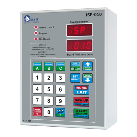
Selbit ISP-12F User manual

MANUAL HANDBOOK
Automatic thickness controller for sawing frame machines
ISP – 12F
Automatic thickness controller ISP-12F is designed to be mounted on the sawing frame
machine.
Before assembly and start please read this handbook manual carefully, instructions
provided help you in correct mounting and operating of our product.

www.selbit.pl
- 2 -
Content:
Chapter 1 – Mounting and connections
Chapter 2 - First start
Chapter 3 – Checking controller’s parameters
Chapter 4 – Quick access buttons A, B, C
Chapter 5 – Normal mode cutting (board after board)
Chapter 6 – Normal mode cutting without board taking out
Chapter 7 – Manual mode cutting (manual program)
Chapter 8 – Automatic saw mode (quickprogram)
Chapter 9 – Program saw mode (A, B, C)
Chapter 10 - Operating order
Chapter 11 – EMC Approval
Chapter 12 – Possible errors and solutions
CHAPTER 1
Mounting and controller’s connections
During controller’s mounting is advised to follow this instructions correctly.
Point - 1
Before mounting in the main board (fig. 1) please cut off rectangle hole 175 x 140 mm.
This hole should be made carefully thus rubber sealing is adjoined to the from panel.
Eventually any irregularity created after incorrect cutting out please smooth them using small
metal file and protect it by anti-corrosion painting. If on the main panel is no place to mount
controller, it is possible to add it as separate device (fig. 2).
Figure 1. Controller mounting on the main board.

www.selbit.pl
- 3 -
Figure 2. Mounted controller as separate device.
In case of controller mounting as a
separate device it is possible after its assembly to attached it to the machine’s frame
using 4 added screws for this purpose. In another case please made special fixing for
mounting the controller which can be used as a distance support as well (fig. 2, E element).
Electric montage
CAUTION !
During electrical assembly there is a possibility of a electric shock thus all actions
should be made while electric power is off. For this purpose please turn off machine’s
main electric switch!!!
All cable connections should be made using special wires with double insulation
oriented for use of the electric devices powered by 230V alternating current. Cables
should be rounded with diameter suitable into holes in the controller back casing
accordingly. Tips of the cables should be cleaned and special quill should be used or
tips should be covered by thin tin layer. Please follow this instructions very carefully
especially electric connections should be made according to provided instructions. It is
required for correct and failure-free controller operating.
Machine where the controller is mounted should be equipped in well working head saw
ending switchers and contactors of the up and down feeding should be protected to be
on at the same time !!!

www.selbit.pl
- 4 -
Point - 2
Power transformer TSS-8/24 assembly
In power cubicle added power transformer
TSS-8/24 needs to be mounted. Mounting is designed for well known and used holding bus
TSS-35. Please place the transformer as far as possible from other electrical elements ( e.g.
frequency changer, contactors, other transformers). It is important because of the
electromagnetic interference which may disturbing controller’s electronics. Please connect to
the connections marked as PRI power supply of 230V. For power supply please choose this
phase of electric supply of the machine which is not connected to the any inductions coils,
contactors or inverters. 230V supply cables should be placed as far as it is possible form other
cables in the power cubicle. To the transformer’s clips marked as SEC 24V please connect
wires which feed electronic plate of the controller. Analogically please place this wires as far
as it is possible from other power cables, especially from 230V which powered the
transformer. Length of the cables (24V) should be chosen accordingly to the place where the
controller is mounted.
Point – 3 Choke CPZ mounting
Anti-disturbance choke CPZ (WX1P 224M 440V)
added in the controller kit is designed to
protect from any other electromagnetic disturbance made by other electrical devices mounted
on the frame machine saw. Its correct mounting is decisive for correct controller operating.
Those CPZ outputs should connected in parallel to the contactors’ coil. CPZ should be
connected with contactor’s coil of the down feeding, up feeding and barker contactor
separately (if the sawing frame machine is equipped with barker).
Fig. 3 Choke CPZ constructions and connections

www.selbit.pl
- 5 -
Point -4
Rotating encoder mounting
Added rotating encoder is designed to convert rotation of the head saw feeding screw for
electrical impulses. Number of the impulses depends on screw pitch and this relation
describes table 1. In most of the frame sawing machines this screw has got free tip where the
encoder can be installed. Please make a concentric hole in the screw and mount encoder’s
clutch. Please make sure that this hole is concentric otherwise it can cause swinging and
eventually incorrect encoder working and its damage. Please make hole around 15 mm and
create thread M8. Next mount encoder using fixing band (fig.4). The band should be attached
to the special fixing which because of the variety of the frame sawing machines should be
created individually. Example of the encoder mounting is shown at the photo 4a below.
Photo 4a. Example of the necoder mounting. Fig. 4 Encoder mounting ex ample.
Table 1
Screw pitch
[mm./obr.] Encoder type
[imp./rotation] Devider
3 Rotating 42 28
4 Rotating 42 21
5 Rotating 50 20
6 Rotating 48 16
7 Rotating 42 12
8 Rotating 48 12
9
Linear MSK320 + MB3200
5
10 Rotating 50 10
Chain sawing frame machine Linear MSK 320 + MB 320
5
Data from table 1 should be used during procedure of checking the controller’s
parameters.
Cable connection of the encoder should be routed as far as it is possible from other electrical
cables. Using special clip bands lead it to the place where the controller is mounted.

www.selbit.pl
- 6 -
Point – 5
Linear magnetic encoder mounting
(version for chain sawing frame machines)
In case of saw head fed with chain the linear magnetic encoder MSK-3200 needs to be used.
It works together with magnetic tape MB-3200.
The magnetic tape contains two parts which contains with self-adhesive layer. First,
thicker part please place on the smooth and flatten surface (please clean the surface carefully
before sticking the tape using acetone or spirit). During sticking please get unstuck only small
part of the tape on the tip and stick it to the surface. Next get unstuck rest of the tape slowly
sticking it to the surface simultaneously. During sticking please use rubber roll to create
bigger adhesive pressure. Please stick the tape very careful and try to not create any air
bulging and notice to stick it straight. Next please stick the second part of the magnetic tape –
steel protection strip using the same proceeding as above. Both tapes should be stuck in one
line laying on each other creating two layers. Sensor MSK-3200 should be mounted on not
moveable part of the machine (according to the controller) to not create any cable movements
which can cause its damage. In case of mounting sensor on moveable part please protect cable
from its non-controlled damage leading it in a special portable buses. Sensor should be
mounted with two screws in a way that the magnetic tape should be in a 1 to 1,5 mm distance
and in parallel with it. Please notice during leading the cable to place it as far as it is possible
from other cables. Please do not place any sources of the magnetic field next to the magnetic
tape during, before and after mounting. It may cause it serious damage and incorrect working
of the controller. Please clean the surface of the tape from time to time with sift brush.
Please do not hit senor or the tape. The sensor should be mounted in that way thus text
SCALE SLIDE is faced on the magnetic tape side. The sensor and the tape should be mounted
in a such way that during feeding sensor “is above” the tape in all range. Please notice the
stability of the tape and the sensor during normal operating.
Fig. 5 Sensor and magnetic tape mounting example

www.selbit.pl
- 7 -
Point 6
Installation of the up and down electronic feed limit switches.
Head movement limit switches are required for the correct operation of the adjuster. The set
includes 2 pcs of electronic magnetic limit switches type TS18-05P-2 Highly.
These are typical contactless sensors that respond to the approach of a metal element marking
the maximum movement of the machine head. These sensors should be mounted into pre-
made holes, using mounting nuts supplied with the sensor. The function of metal elements
activating the limit switch can be provided by angles attached to the moving part of the head
passing the face of the sensor at a distance of 2–4 mm. When routing the cable from the limit
switches, make sure that they are as far away as possible from other cables and power
devices.
Remember that there is a specific time interval between the moment the limit switch is
activated until the head stops, depending on the mechanical inertia of the machine. During
that time, the head passes a certain distance, therefore it is not possible to mount the sensor in
such a way that the activating metal element interferes with the location of the sensor (Figure
6). It is also necessary to provide for the possibility of changing (adjusting) the mounting
place of the metal element activating the limit switch so as to adjust the switch-off point of the
drive during the start-up of the adjuster.
Instead of electronic limit switches, you can also use good quality mechanical limit switches
with NC terminals, connecting them to the adjuster as shown in Figure 8.

www.selbit.pl
- 8 -
Figure 6
Electrical connections of external components to the adjuster.
Before connecting the wires, it is absolutely necessary to turn off the power supply of the
converter and the ISP-12F adjuster!
Connection of control inputs of the frequency converter
For connection, use an 8-core screened control cable with a cross-section adapted to the
connection terminals.
The isolated ends of the individual conductors should be tightened in collets appropriate for
the given cross section; the use of collets improves electrical contact and prevents breaks in
connections. The screen (braid) of the cable should be connected to the connection only from
the side of the frequency converter!
Connection of cables from the adjuster to the converter should be made according to the
following description:

www.selbit.pl
- 9 -
Connector of the adjuster Connections of the frequency converter
ISP-12F (PWR CONVERTER ATV 320 3*380V)
+24 ------------------------------------------------------ +24
GND (-24V) ------------------------------------------- COM
L6 ------------------------------------------------------- DI6
L5 ------------------------------------------------------- DI5
L4 ------------------------------------------------------- DI4
L3 ------------------------------------------------------- DI3
L2 ------------------------------------------------------- DI2
L1 ------------------------------------------------------- DI1
The screen (braid) - COM connect only from the side of the inverter!
Figure 7
Connection of electrical terminals of the ATV 320 converter
Prepared cables connections and casing assembly of the controller.
Please connect power cable TS 8/24 (SEC,12 V), (with prepared cables’ tips) to the junction
marked as PWR on the controller’s main plate.
Rotating encoder’s connection:
Encoder cables please connect with junctions marked ENCODER as follow:
-brown cable with (+24) plus controller’s connection
-blue cable with (GND) minus controller’s connection
-white cable with (IN-1) connection
-black cable with (IN-2) connection.

www.selbit.pl
- 10 -
Magnetic encoder’s connection MSK-320 in chain sawing frame machine:
Magnetic encoder cables please connect with junctions marked ENCODER as follow:
-brown cable of MSK-320 with controller’s junction marked as (+24) plus
-black cable of MSK-320 with controller’s junction marked as (GND) minus
-red cable of MSK-320 with controller’s junction marked as IN-1
-orange cable of MSK-320 with controller’s junction marked as IN-2
CAUTION!!!
Incorrect connection of the rotating or magnetic encoder may cause its serious damage!!
Connection of TS18-05P-2 electronic limit switches:
Connect the limit switch restricting the downward movement to the MPS-DWN connector of
the adjuster:
- brown to connector +24
- blue to connector GND
- black for connector IN
Similarly, connect the limit switch restricting the upward movement, this time to the MPS-UP
connector.
Instead of electronic you can use electromechanical switches and connect them as shown in
the figure.
Figure 8
Wiring diagram for electromechanical limit switches

www.selbit.pl
- 11 -
Figure 9
Wiring diagram for manual remote control buttons
Figure 10
Block diagram for MSK 320 magnetic encoder

www.selbit.pl
- 12 -
Figure 11
Block diagram for rotary encoder

www.selbit.pl
- 13 -
Next step after creating all of the connections is assembly of the controller’s casing. Before
connecting from panel with the back side please check if the rubber sealing is in the special
groove. It is important in regarding sealing and protecting controller’s main electronic plate
from any contamination. After put the from panel in together with the back side please screw
casing using included six screws 4,1x12. Before mounting the controller on the machine it is
recommended to checking of proper controller’s operating according to “first start” chapter
(2). After checking of the controller’s proper operating please use safety plugs in the places
where screws are and mount the controller on the machine. Controller’s mounting in the main
machine’s board is analogical, there is only one difference that front panel is screwed from
the inside with plastic frame and main panel casing. After all mounting please carefully pull
out cables which go out at the back side of the controller’s casing to reduce their unnecessary
length in the inside. Please be careful to not destroy any connection. After this operation
please screw PG choke to create proper sealing. Next step, in case the controller as a separate
devise, please mount it using four 4,1x10 screws on the sawing frame machine. Screws should
go though four holes in the back casing created for this purpose.
Chapter 2
First-time start-up
Some of the converter settings must be adapted to your drive before operation
(parameters of the head feed motor, moment of inertia of the drive and related
acceleration and deceleration ramp times).
Attention!
The configuration of the adjuster requires basic technical knowledge related to the
practical application of the said devices and should be performed by a person with
appropriate professional qualifications.
Correct configuration requires the exact programming sequence K1-K9!
Programming the frequency converter.
Attention!
Programming of the frequency converter parameters should be performed while it is
turned on but not executing control commands and the display shows the message "rdy"
The time parameters of the acceleration and deceleration ramp should be selected
depending on the weight of the moving parts of the machine head drive and the travel
speed of the drive.
In order to optimize the stopping time of the head, appropriate brake resistors should be
used, matching the performance of the frequency converter.
When determining ramp times, make sure that they are not too small in relation to the
machine's inertia.

www.selbit.pl
- 14 -
A too short stopping time may cause an overload of the converter (exceeding the
maximum feedback voltage on the capacitors), which will cause the converter to stop
operating and display an appropriate error message.
To enter the menu, press the rotary knob of the ATV 320 converter while the “rdy”
message is being displayed, then turn the knob to select a further menu. Use the knob to
change the value of the set parameter and press to save the changes.
When the function value in the menu is changed, the LEDs on the display start to flash
and the changed value is confirmed by pressing the knob.
To exit a menu, press the ESC button next to the knob.
If the ATV 320 frequency converter is supplied with the adjuster, some parameters are
already pre-set. In such a case, only the function parameters marked in grey should be
modified.
If the converter is not supplied with the adjuster, a full configuration of functions should
be made, as described in all tables!
(K-1) Setting of electrical parameters of the drive:
Input by: ConF – FULL – Sin -
Function Value Description of the function
bFr (from the motor name
plate) Motor rated frequency (Hz)
UnS (from the motor name
plate) Motor rated voltage (V)
nCr (from the motor name
plate) Motor rated current (A)
Frs (from the motor name
plate) Motor rated frequency (as above) (Hz)
nSP (from the motor name
plate) Rated engine speed (rpm/min)
tFr = > 50Hz Maximum output frequency (Hz)
tUn No Auto tuning engine inactive
itH (from the motor name
plate) Motor thermal current (A)
ACC Optimal selection for the
speed and inertia of the
machine
Converter acceleration ramp time (s)
Attention! Define the ramp time after activating the
adjuster
dEC Optimal selection for the
speed and inertia of the
machine
Converter deceleration ramp time (s)
Attention! Define the ramp time after activating the
adjuster
LSP 0.0 Minimum speed (Hz)
HSP <= from the value set in
the function tFr Maximum speed (Hz)

www.selbit.pl
- 15 -
(K-2) Setting of electrical parameters of the drive (continued)
Input by: ConF – FULL – drC -
Function Value Description of the function
Ctt UUC Voltage vector control
(K-3) Configuration of control inputs
Input by: ConF – FULL – I-O -
Function Value Description of the function
tCC 2C 2-wire control
tCt trn Status change is required to trigger the input
Frd LII Terminal DI1 triggers downward motion (forward)
rrS LI2 Terminal Di2 triggers upward movement (backward)
(K-4) Configuration of control inputs (continued)
Input by: ConF – FULL – Fun – PSS -
Function Value Description of the function
PS2 LI3 Terminal DI3 triggers the set speed
PS4 LI4 Terminal DI4 triggers the set speed
SP2 10 Second set speed (not used)
SP3 10 Frequency of free movement to position (Hz)
SP4 = > from the value
set in the function tFr Frequency of fast motion (Hz)
(K-5) Configuration of control inputs (continued)
Input by: ConF – FULL – Fun – LPO-
Function Value Description of the function
SAF LI6 Terminal DI6 – limit switch down
SAr LI5 Terminal DI5 – limit switch up
SAL LO Triggering with a low logic state from limit switches
PAS rnP Type of stop after a signal from limit switches (ramp)
dSF Std Type of stop (standard)
nSTP nO Limit switch operation memory (off)

www.selbit.pl
- 16 -
(K-6) Configuration of control inputs (continued)
Input by: ConF – FULL – I-O – L1 do L6 -
Function Value Description of the function
L1d to L6d 1 Delay of the input lines DI1 to DI6 (ms)
(K-7) DC current braking configuration.
Input by: ConF – FULL – Fun – AdC
Function Value Description of the function
AdC yES DC current braking is on
(K-8) DC current braking configuration (continued)
Input by: ConF – FULL – Set –
Function Value Description of the function
tdC1 0.5 DC braking time after stopping (s)
SdC1 < rated current DC braking current value (A)
Attention!
Due to the phenomenon of mechanical head lowering during vibrations occurring in the
cutting process, the recommended option is to install a drive brake with an
electromagnetic release.
The application of this solution keeps the head fixed in position during the entire cutting
process.
To control the brake release, use the R2A R2C relay output and program it as described
(K-9) Configuration of the brake (electromagnetic release).
Input by: ConF – FULL – Fun – bLC
Function Value Description of the function
bLC r2 The R2 relay controls the release
bIP nO Impulse of the direction of rotation –no
Ibr 0.0 Brake release current (A)
brt 0.00 Time needed to mechanically release the brake (set a different value if
necessary [s])
bEn Auto Brake frequency threshold
bEt 0.00 Mechanical brake engage time
(set a different value if necessary [s])

www.selbit.pl
- 17 -
For any additional information, please refer to the operating instructions of the ATV
320 converter manufacturer.
After fine-tuning of the parameters and checking the correctness of the operation of the
adjuster cooperating with the converter, save the configuration made to the ATV 320
memory so that it can be quickly restored if necessary.
Custom settings should be saved in the converter memory in configuration number 2(Str2 –
CFG2)
Configuration number 1(CFG1) contains pre-set settings supporting the ISP-12F adjuster
but does not contain drive parameter values; it is only used for the initial configuration.
Saving your custom configuration in the converter memory (Str2):
rdy – ConF – FCS –
Function Value Description of the function
Fry- ALL When the message ALL is displayed, press the knob so that the two
vertical bars on the right side of the display are displayed at the top
and then press ESC
SCSI Str2 Selected configuration set number 2. Press the knob and hold for> 3s
until the dots on the display stop flashing
The configuration that is currently loaded into the converter cannot be selected for
saving. For example, if the converter is currently operating using the configuration
number 1, then you can only select configuration number 2 or restore factory settings
(InI).
Recovering a previously saved configuration from the machine's memory, (CFG2):
rdy – ConF – FCS –
Function Value Description of the function
FCSI CFG2 Selected restore factory configuration
Fry- ALL When the message ALL is displayed, press the knob so that the two
vertical bars on the right side of the display are displayed at the top
and then press ESC
GFS YES After changing the message to YES, press and hold the knob for > 2s
until the dots on the display stops flashing
If the converter is supplied with the ISP-12F adjuster, you can restore the initial
configuration as described above by selecting the CFG1 name in the FCSI function.
Restoring factory settings of the ATV 320 converter
If necessary, you can restore the factory settings (it does not include the initial
configurations for the ISP-12F adjuster)
After restoring the factory settings, set all the required parameters according to the
operating instructions!

www.selbit.pl
- 18 -
Restore factory configuration of the converter:
rdy – ConF – FCS –
Function Value Description of the function
FCSI INI Selected restore factory configuration
Fry- ALL When the message ALL is displayed, press the knob so that the two
vertical bars on the right side of the display are displayed at the top
and then press ESC
GFS YES After changing the message to YES, press and hold the knob for > 2s
until the dots on the display stops flashing
After correct configuration of the converter, check the operation of the ISP-12F adjuster
Start-up of the ISP-12F adjuster
To check the correctness of connections, follow the steps below:
-After switching on the power supply, check whether the message ISP 12F is displayed. If
not, check the TSS 8/24 transformer connections and try again.
-After the ISP 12F message disappears, press the button of the manual control of the
headdownwards and check whether the head moves down; if the head moves in the
opposite direction (up) change positions of two out of three phase wires feeding the
head engine.
-Press and hold for a moment the “down” button of the manual control of the head on the
machine desktop. During manual lowering of the head, pay attention to whether the
dimension displayed in the “Saw Height” window decreases along with the downward
movement of the head. Similarly, by pressing the “up” button of the manual control of the
head, the dimension in the “Saw Height” window should increase along with the upward
movement of the head. If the counter malfunctions, i.e. the displayed value decreases
when the head is moved up and increases during the downward movement, swap the black
and the white wire (in the case of a rotary encoder) or the red and the orange wire (if the
MSK-320 magnetic encoder is used), (ENCODER, terminal In1, In2) and check the
operation of the counter again. Checking the correctness of counting is very important; if
the counting direction is not correct, the adjuster will not operate.
Finally, check that the limit switches limiting the movement of the head up and down
operate correctly. Limit switches should be fine-tuned to ensure safe stopping of the
head in extreme positions when reaching the full speed (test approach motion should be
at least 100 mm); when the movement stops, the adjuster displays the message “dn
STOP” or “UP STOP”, depending on the limit switch activated.
After activating the adjuster, the ATV 320 converter acceleration and deceleration ramp
time should be carefully selected (Table K-1, setting the electrical parameters of the
drive, ACC and Dec function).
The appropriate selection of ramp times should ensure the fastest possible acceleration
from the 0Hz frequency to the maximum operating frequency, as well as the fastest
possible release from the maximum operating frequency to 0Hz. The deceleration ramp
time must be selected so that even in the most adverse conditions, stopping the drive
does not cause the converter to enter emergency mode due to excessive voltage generated
at the motor terminals.

www.selbit.pl
- 19 -
The optimal operation of the deceleration ramp ensures the use of braking resistors in
this type of positioning applications.
Limit switches as well as their triggers should be properly mounted and tightened
as it affects their operation!
If the verification of connections according to the description above has been completed
successfully, you can proceed to the next stage of the start-up (Chapter 3).
CHAPTER 3
Controller’s parameters checking
To use those instructions it is required to check pitch of the feeding screw. Please measure it
and write it down below:
Pitch screw in this machine is ……………. Mm
Next, please check type of the encoder mounted on this machine at the end of the screw
(photo 4a). Encoder’s type is marked on its casing and shows impulses to rotation ratio
generating. Please note this number below:
Encoder’s impulses to rotation ratio mounted on this machine is ………… imp/rot.
Next, using table 1 from point 4 of this instruction check which divider is correct for this
sawing frame machine. Example: for pitch screw 7 mm and encoder’s impulses to rotation
ratio 42 imp/rot. divider read from the table is 12.
After checking this values please note it below:
Divider (table 1) …………………
If the controller is mounted on the chain sawing frame machine thus divider according
to the table 1 is 5.
For checking all controller’s parameters, please follow points 1…5 below.
1- Input divider checking
For checking input divider value please turn on the controller and during the ISP 12F is
displayed please press “Clibr.” button. The controller display in “Board Thickness” window
divider symbol at the left side and its value at the right one. Please compare read value with
value which should be provided from the table 1. If the value is not correct, please type in
required one and save it to the controller’s memory pressing “Start/Next Cut” button. Text
“Save” should be shown.

www.selbit.pl
- 20 -
Please notice that after setting up the input divider it is needed to
follow next starting instructions otherwise the controller will not
work properly.
2 – Saw trace value checking
To check and eventually change the value of the saw trace please hold for 3 seconds
button with saw symbol. The symbol of the saw trace and its value will be displayed. Now
there is a possibility to check and eventually change this value depends on the saw type used.
Typing in the saw trace please notice that the value is round off to one place after the come.
Example: if you want to type 2 mm first press 2 button and then 0. On the screen 2.0 value
will be displayed. After checking and eventually changing the value of the saw trace to save it
to the controller’s memory pressing “Start/Next Cut” button. Text “Save” should be shown.
Other Selbit Controllers manuals
Popular Controllers manuals by other brands

Cumberland
Cumberland PNEG-881 Installation and operation manual

BZ PRODUCTS
BZ PRODUCTS M20+ installation manual

Siemens
Siemens MEC 1100 installation instructions
Helios
Helios EDR Installation and operation
DPS Telecom
DPS Telecom NetGuardian LPG D-PK-NGLPG user manual
Emerson
Emerson EZH instruction manual
Linak
Linak TECHLINE LA25 Connection diagram
Emerson
Emerson DIXELL XR30T Installing and operating instructions
Braglia
Braglia M202 Installation, use and maintenance

Daitsu
Daitsu CDV-46 manual
TechGrow
TechGrow Humi Dual Pro Series user manual
TeeJet Technologies
TeeJet Technologies DYNAJET IC7 140 user manual
