Selden TYPE RB Mk 4 User manual
Contents: Page: Contents: Page:
Product Description 2 Fitting and Hoisting the Sail 8
Checks and Adjustments Before Stepping 4 Before Sailing 9
Line Routing 6 Maintenance 10
Operation 7
Manual for Furling mast
TYPE RB Mk 4
595-065-E
2017-03-06

2
Product description
• Seldénfurlingmastisamainsailreengandfurlingsystem.
• Theuniquedesignofthehalyardswivelbearingdistributestheloadoverthewholeballracetogive
smootherfurlingandthelowestpossiblefriction,evenunderhighloads.
• ThenewMk4compactgearmechanismoffersimprovedgearefciency,allowsasmallermastcutout
andispreparedforeasyretrotofelectricfurlingdriveunit.
• ThisInstructionManualhasbeencompiledtogiveyouinformationonthein-mastreengsystem.
Studyitandfollowtheinstructionscarefully,andweguaranteeyoupleasurableusefromyour
Seldénfurlingmast.
Followtherelevantrigginginstructionsinourbooklet”HINTSANDADVICE”fortuningtherig.
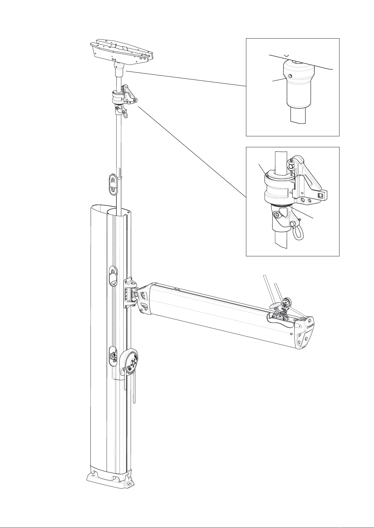
Sail compartment with luff extrusion
Fig. 2:1

3
Top swivel
Halyard swivel
Sail feeder
Outhaul car
Access to sail feeder and
halyard swivel
Access to tack hook and
tensioning screw
Fig 3:1
Tack hook
Rachet lever
Line driver
Tensioning screw
Winch handle socket
4
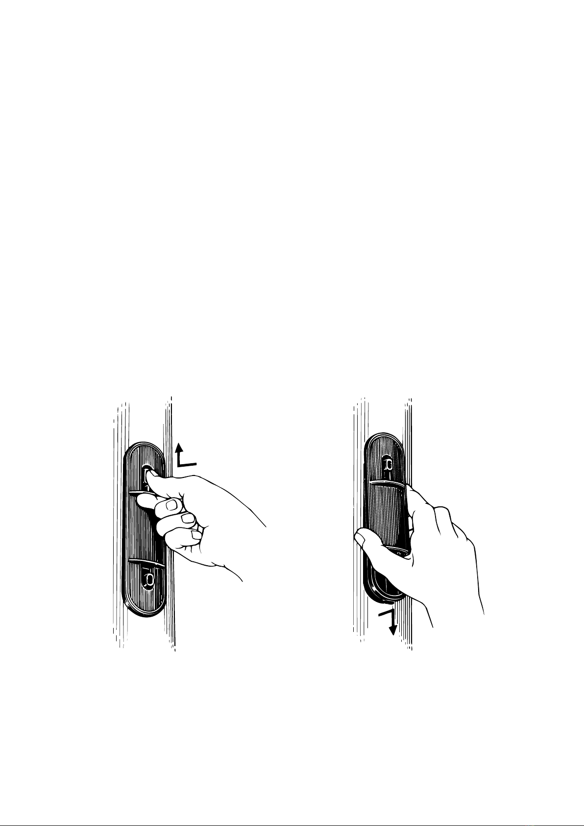
1. Remove the access covers.
Depress one button and push. Lift the opposite end and remove.
Fig. 4:1 Fig. 4:2
Luff extrusion adjustment
Checking luff extrusion tension prior to stepping the mast
Theluffextrusioniscorrectlytensionedbeforeleavingthefactory,buttensioncanbere-checkedbeforestepping
themastinthefollowingmanner.
Laythemasthorizontallyonit´ssideandkeepitstraight.Theluffextrusionshouldnowbejustclearoffthemast
wallatitsmidpoint.Ifadjustmentisnecessaryseepoints1-5below.
Ifadjustmenthastobemadeafterthemasthasbeenstepped,thentheluffextrusionshouldbesotensionedthatit
doesnotbeatagainstthemastwallwhenyougraspitthroughtheupperaccessholeandshakeit.
Theluffextrusioncanbetensionedalsowiththesailttedifthewindsareverylight;Rolloutthesail,lowerit
slightlyandremovethetackfromthetackhook.Hoistthesailsoitdoesnotinterferewithtensionscrew.
Partoftheextrusionwillberestingontheaftfaceofthesailcompartmentwhensailing.
DONOTOVER-TENSION!Aluffextrusionthatisover-tensionedwillrequireincreasedfurlingeffort.
5
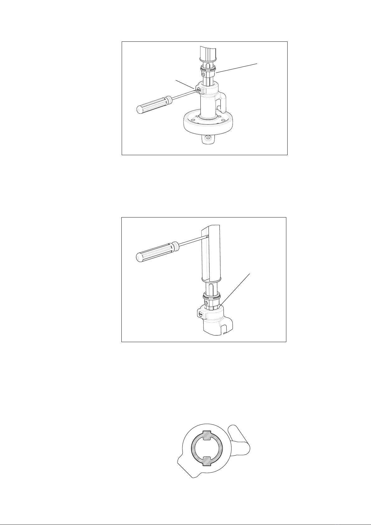
Releasethelockingscrew!3turnsandliftthelockingring".Lockingringcanbetemporarilysecuredby
apieceoftape.
Lubricatethetensionscrewwithriggingscrewoil(art.nr312-502).Putascrewdriverinthesailgrooveofthe
luffproletopreventitfromrotating.Apieceoftapeonthetipofthescrewdriverpreventsdamagetotheluff
prole.Turnthereengwinchusingthewinchhandleuntiltheluffproleiscorrectlytensioned.
4dropsofoil
2. Release locking ring
3. Adjust luff tension
!
"
3. Engage locking ring in position and tighten locking screw
5. Refit access covers.

6
Alternative clew outhaul arrangement.
Fig. 7:1 Fig. 7:2
Layout 1
Figs.6:suggestedarrangement.
Line routing
Reengandunreengisaccomplishedwithanendlessreenglineandanouthauloperatedeitherfromthecockpit
oratthemast.Inthelattercasetheouthaulisalsotakentotheboomormastnearthegooseneck.(SeeFig.7.1).
Endless reefing line
Ifin-mastfurlingmastistobeoperatedfromthecockpitanendlessreengline(loop)incombinationwithaself-
tailingwinchisrecommended.Reenglineshouldbeø10mmpolyesterrope.Theendlessloopmusthaveextra
lengthtoallowittobeeasilyremovedfromthewinch.Thetail-endoftheloopmustalsobebelayedonastopper.
Onmostinstallations,thereenglineneedstobefedthroughblocksandstoppersbeforemakinganendlesssplice
accordingtoSeldéninstruction595-673.Iftheblocksandstoppersarepossibletodismantle,asplicedendlessline
canbeusedaccordingtosparepartslistatpage15.
Outhaul line
Aself-tailingwinchandastopperisalsorecommendedfortheouthaulline.
FreeRatchet
Lead Blocks
Lead Blocks
Turning Blocks
Kicking Strap
Rope-Stoppers
Topping Lift
Endless Reeng
Line
Fig 6:2
Outhaul

7
Operation
Furlingandunfurlingisaccomplishedeitherfromthecockpitwithanendlessreenglineandanouthaullineorat
themastusingawinchhandleatthemastlinedriver.Inthelattercasetheouthaulistakentotheboomormastnear
thegooseneck.(SeeFig.7.1).
Unfurling
Whenunfurlingfromthecockpitthelinedrivermustbesetto”free”.(SeeFig.7:2).
1. Freebothsidesoftheendlessloopfromthewinchandstopper.Itwillthenslideonthelinedriver.
2. Pulloutthesailwiththeouthaulline.
Furling
1. Theleechshouldbekeptfairlytightwhenreengorfurling.Adjusttheboomangle(vangortoppinglift)
toachievethis,andthesailwillformatightrollaroundtheluffextrusion.
2.Locatethestarboardpartoftheendlessfurlinglineonthewinchandpullbyhand,orifnecessaryusea
winchhandle.
3. Keepslighttensionontheouthaulwhiledoingthis.Thisappliesespeciallywhenthewindisabaftthebeam
orinlightair.
Reefing
1. Carefullyslackenofftheouthaulline.
2. Locatethestarboardpartoftheendlessfurlinglineonthewinchandpullbyhand,orifnecessaryuseawinch.
3. Theleechshouldbekeptfairlytight.Keepslighttensionontheouthaulduringthemaneuver.
Whenworkingatthemast:
Activatethelockonthelinedrive(-IN’)beforereengthesail.Useawinchhandletofurlthesail.When
thedesiredamountofsailisrolledin,usetheouthaultostretchthefootofthesail.Don´t leave the winch
handle in the linedriver!
Whenoperatingfromthecockpit:
Whenreefedtodesiredsailarea,lockbothpartsoftheendlesslinesinstoppersandtightentolockthereeng
winch.Finally,tensiontheouthaul.
When leaving the boat.
Alwayslockthelinedriverwiththeratchetleverwhenleavingtheboat!
WARNING! Never leave the winch handle in the linedriver!
It will rotate very rapidly when the sail is unfurled.
8
Fitting and hoisting sail
CheckthattheTackandHeadofthesailaremadeinaccordancewithSeldéninstruction595-542“Sailmakersguide”.
Anincorrectdesigncancausewrinklesinthesailandmakesmoothfurlingdifcult.
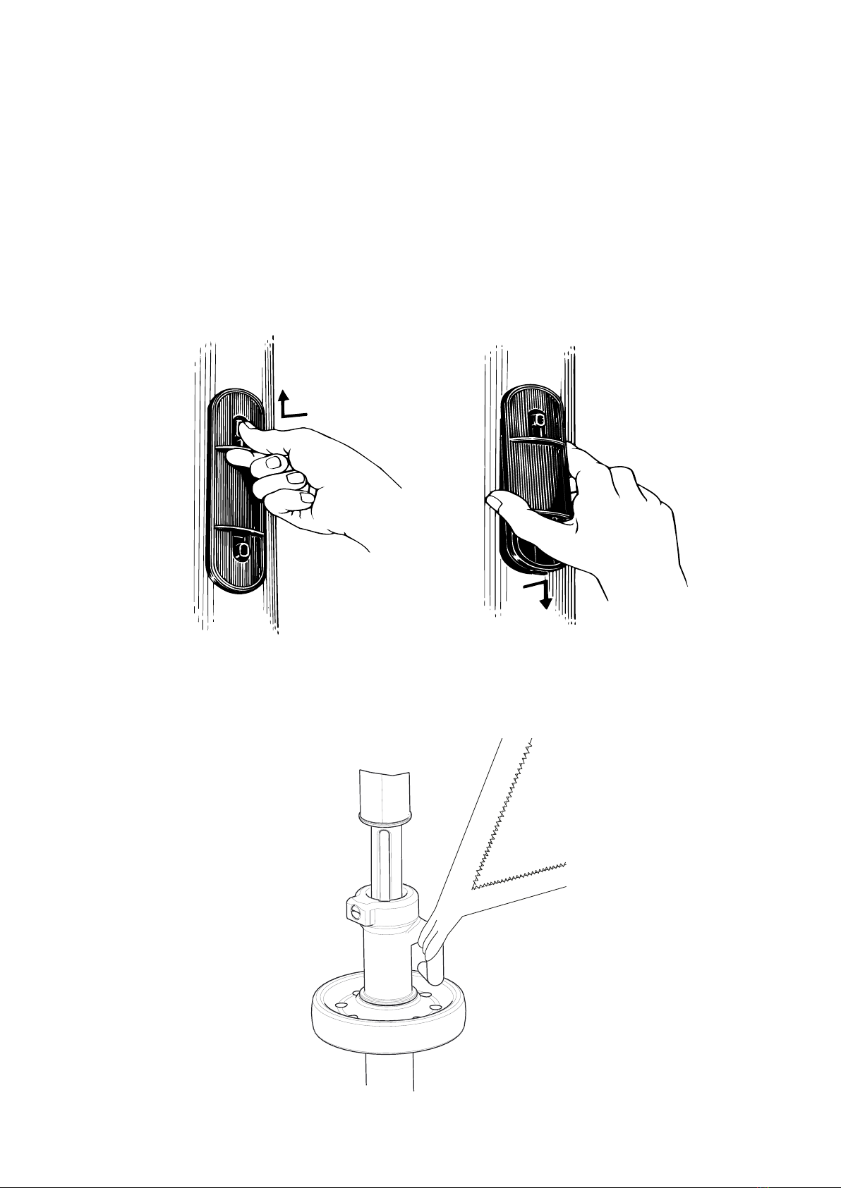
1. Removethecovers.Pressonebuttonandpush.Lifttheoppositeendandremove.Pressonebuttonandpush.
Lifttheoppositeendandremove.
2. Attachtheheadofthesailtothehalyardswivel.
Remove the covers.
Depress one button and push. Lift the opposite end and remove.
Fig. 8:1 Fig. 8:2
Fig. 8:3

9
Sail dimensions
Foruptodatesaildesigninformation,pleaseseethesailmakersguide,595-542-E.
Port
Fig. 9:1
Starboard
Before sailing
1. CheckthatthesailiscorrectlyfurledontheSTARBOARDSIDEoftheluffextrusion.(SeeFig.9:1).
2. Furlandunfurlthesailacoupleoftimestoensurethatthesystemworksasitshould,andtofamiliarize
yourselfwithitsoperation,andalsotocheckthatthesailiscorrectsize.
3. Theareaaftofthemastmustbefreefromhalyardsetc.orthesecanbecaughtbythesailduringthe
furlingprocedure.
Note. For correct furling, pull on starboard part of the endless
furling line for the line driver to turn clockwise.
4. AttachtheclewtotheOuthaulCar.
5. Hoistthemainsailwhilstsimultaneouslyensuringthatitisfeedingcorrectlyintotheluffextrusion.
6. Jointhesailtothetackhook.(Seeg.8:3).
7. Tightenthehalyard.
8. Furlthesailuntilonly200-300mmoftheclewisexposed.Thelinedrivershouldbeturnedclockwise.
(SeeFig.9:1).

10
Maintenance of the in-mast furling mast
Periodic Maintenance
Maintenanceshouldbeundertakenatleastonceayear.Morefrequentcleaningforremovalofsaltandsand
isdonebyrinsingwithfreshwateronly.AllbearingsshouldbegreasedwithGREASE(PartNo.312-501),
atubeofwhichisdeliveredwiththemast.ReadthefollowinginstructionsandseeFig.13:l.
Whengreasingbearingsandgears,donotover-grease.Athincoatingofevenlyappliedgreaseissufcient.
TOP SWIVEL:
Thebearinghasalubricationholemarked”GREASE”wherethegreaseshouldbeinjected.Accessthroughthe
sailslot.
HALYARD SWIVEL:
Lubricatetheswivelbyinjectinggreaseintothegaps& inthering.Thisisbestdonethroughtheupperaccess
hole.
IN-MAST FURLING MAST GEAR.
1. Removetheaccesscoversandun-tensiontheluff-seepages4&5.
2. Removeratchetcoverassembly .
3. Greasethebevelgears andball-bearing .
Complete Service
Itisagoodideaaftersomeyearsusetoremovethegearforthoroughcleaningandre-greasing.Thein-mastfurling
mastisbuiltsothatservicingwillbeeasyevenafterprotracteduse.Topswivel,halyardswivelandfurlinggearcan
becleanedinkerosene,bloweddrywithcompressedairandre-greased.
Removal of the gear
1. Relievetensionontheluffextrusionbyslackeningthetensioningscrewasdescribedonpage4-5.
2. Removethe2insexscrewsholdingthefurlinggearandtheratchetcover.
3. Releasethetwoscrewsattheballfurlinggearjoinconnectiontoreleasethefurlinggearandtakeoutthegear
viatheratchetcoverhole.
Removal of the top swivel and halyard swivel.
Thiscanonlybedonewiththemastdown.
1. Relievetensionontheluffextrusionbyslackeningthetensioning
screwasdescribedonpage4-5.
2.Releasetheheadboxbyundoingthenutsontop.Liftoffthe
headboxwhileyoufollowwithreleasingthetensioningscrewuntil
itseparatesfully.Theboxcanthenbeliftedoff.DetachtheTop
Swivelfromtheheadbox.
3. TheluffsectionandtheHalyardSwivelcannowbepulledoutof
themast.
11
Fig. 13:1
1212
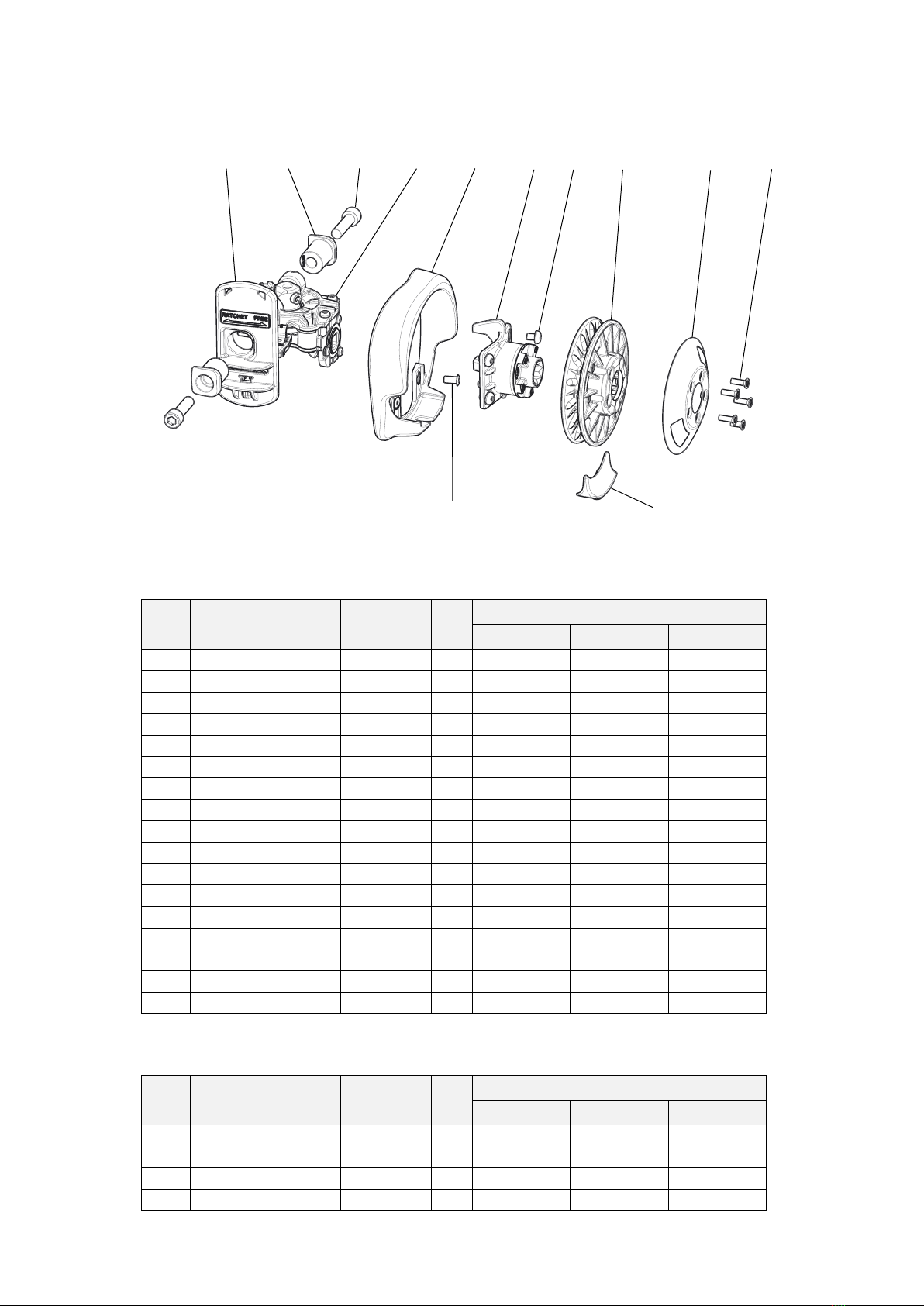
Spare parts
Furling gear
Item Description Dimension Qty Mast extrusion
F228 F246 F265
1 Gear house assembly - 1 540-090-01 540-090-01 540-090-01
2 Ratchet cover assembly - 1 540-392-01 540-392-01 540-392-01
3 Flange bush Ø23/10.5-28 2 540-388 - -
3 Flange bush Ø23/10.5-32 2 - 540-389 -
3 Flange bush Ø23/10.5-36 2 - - 540-390
4 Screw MC6S 10x30 2 153-059 - -
4 Screw MC6S 10x35 2 - 153-061 -
4 Screw MC6S 10x35 2 - - 153-061
5 Line driver cover 142x148 1 540-089 540-089 540-089
6 Pop rivet Ø6.4x12.7 4 167-004 167-004 167-004
7 Bearing house assy - 1 540-087-01 540-087-01 -
7 Bearing house assy - 1 - - 540-087-02
8 Screw MRT 6x8 4 155-624 155-624 155-624
9 Linedriver assembly Ø120x33 1 540-085-01 540-085-01 540-085-01
10 Stripper 58x20 1 540-034 540-034 540-034
11 Cover ø112x29 1 540-194 540-194 540-194
12 Screw MFT5x12 5 162-048 162-048 162-048
ab c hgd e
f
i
j
k l
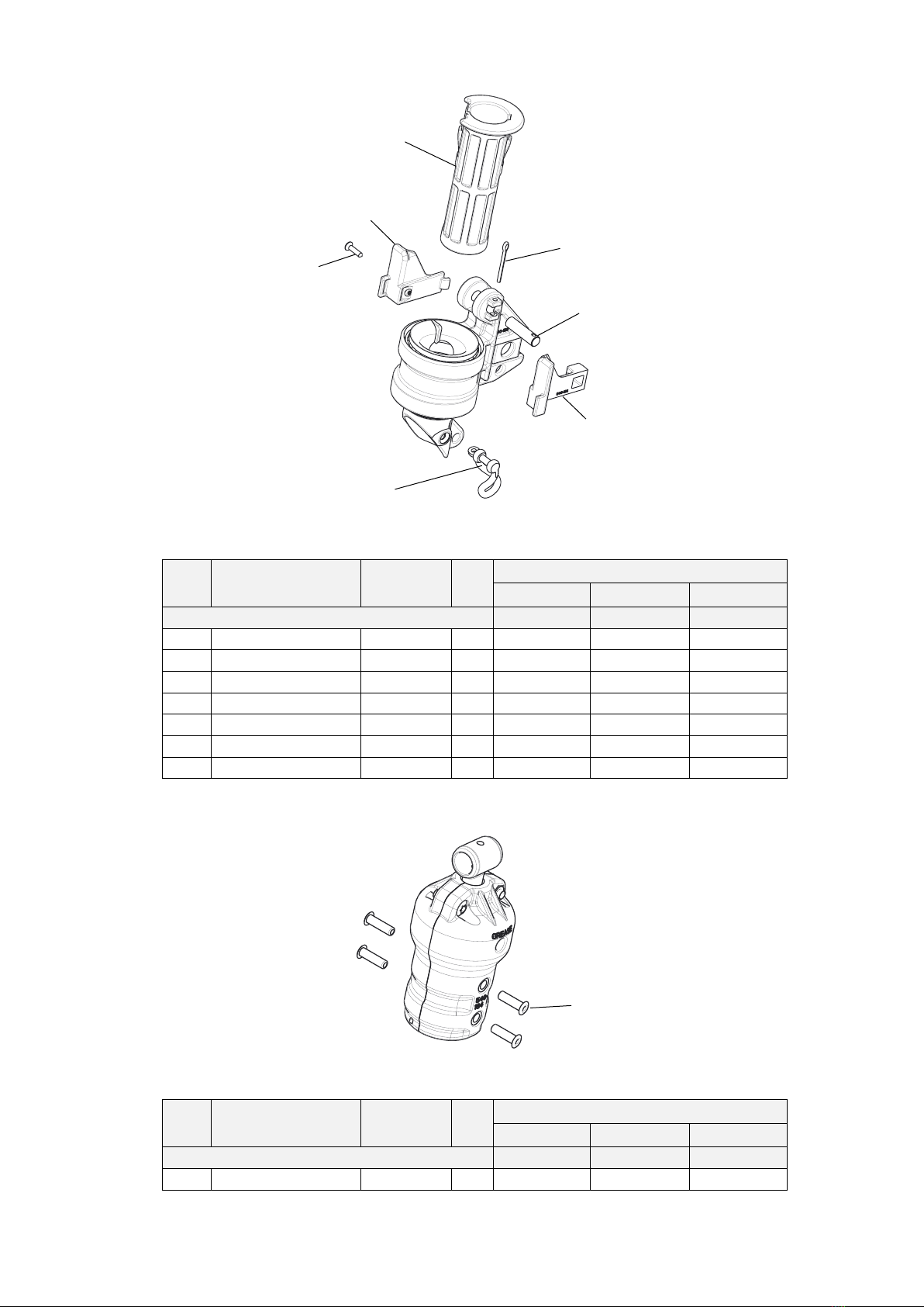
Sail feeder tube assembly
Item Description Dimension Qty Mast extrusion
F228 F246 F265
13 Sail feeder tube 30/29-524 1 540-381 540-381 540-381
14 Joint sleeve L=192 1 540-167 540-167 540-167
15 Pop rivet 4.8x9.9 4 167-007 167-007 167-007
16 Sail feeder 32x12 1 540-344 540-344 540-344

1313
Tack assembly
Item Description Dimension Qty Mast extrusion
F228 F246 F265
17 Tack hook body 37x117 1 540-100 540-100 540-100
18 Tensioning screw M22x165 1 540-099 540-099 540-099
19 Torque connector 30x17 2 540-098 540-098 540-098
20 Retaining ring - 1 301-063 301-063 301-063
21 Screw MC6S 5x6 1 155-072 155-072 155-072
22 Wheel ø90/31-20 1 319-622 319-622 319-622
23 Split pin 3.7x40 1 301-062 301-062 301-062
24 Pop rivet 4.8x9.9 4 167-007 167-007 167-007
Shaft assembly
Item Description Dimension Qty Mast extrusion
F228 F246 F265
25 Shaft Ø25x356 1 540-399 540-399 540-399
26 Gimbal joint Ø34/32-49 2 540-097 540-097 540-097
27 Clevis pin Ø10x40 2 165-211 165-211 165-211
28 Split pin 2.9x16 2 301-049 301-049 301-049
29 Clevis pin Ø10x40 1 165-211 165-211 165-211
30 Split pin 2.9x16 1 301-049 301-049 301-049
Luff extrusion
Item Description Dimension Qty Mast extrusion
F228 F246 F265
31 Luff extrusion w. cover L=7500 1 540-111-01 540-111-01 540-111-01
32 Joining sleeve L=180 1 540-148 540-148 540-148
33 Pop rivet 4.8x9.9 8 167-007 167-007 167-007
13
14
15
16
17
18
19
20
21
27
26
25
24
23
22
28
32
31
30
29
33
14
a
b
c
g
d
e
f
Halyard swivel
Item Description Dimension Qty Mast extrusion
F228 F246 F265
Complete halyard swivel -> 540-158-01 540-158-01 540-158-01
1 Sliding sleeve 64x140 1 540-159 540-159 540-159
2 Sliding insert-stb 52x52 1 540-165 540-165 540-165
3 Sliding insert-port 52x52 1 540-166 540-166 540-166
4 Screw 3.5x9.5 1 171-047 171-047 171-047
5 Schackle M7/13/25 1 307-023 307-023 307-023
6 Pin ø10x37 1 166-222 166-222 166-222
7 Split pin 2.9x32 1 301-525 301-525 301-525
Top swivel
Item Description Dimension Qty Mast extrusion
F228 F246 F265
Complete top swivel (pop rivets not included)-> 540-164-01 540-164-01 540-164-01
1 Pop rivet 4.8x16.5 4 167-006 167-006 167-006
a

15
Additional items
Item Description Dimension Qty Mast extrusion
F228 F246 F265
1 Grease 100g 1 312-501 312-501 312-501
2 Access hole cover 57x126 1 540-026 540-026 540-026
3 Manual/Spare parts
list-Swedish
A4 1 595-065-S 595-065-S 595-065-S
3 Manual/Spare parts
list-English
A4 1 595-065-E 595-065-E 595-065-E
3 Manual/Spare parts
list-German
A4 A4 595-065-T 595-065-T 595-065-T
4 Endless line Ø10 2x5000 1 611-011-05 - -
4 Endless line Ø10 2x7000 1 - 611-011-06 -
4 Endless line Ø10 2x9000 1 - - 611-011-07
12
34

595-065-E Printed in Sweden
Seldén Mast AB, Sweden
Tel +46 (0)31 69 69 00
Fax +46 (0)31 29 71 37
Seldén Mast Limited, UK
Tel +44 (0) 1329 504000
Fax +44 (0) 1329 504049
e-mail [email protected]
Seldén Mast Inc., USA
Tel +1 843-760-6278
Fax +1 843-760-1220
e-mail [email protected]
Seldén Mast A/S, DK
Tel +45 39 18 44 00
Fax +45 39 27 17 00
Seldén Mid Europe B.V., NL
Tel +31 (0) 111-698 120
Fax +31 (0) 111-698 130
e-mail [email protected]
Seldén Mast SAS, FR
Tel +33 (0) 251 362 110
Fax +33 (0) 251 362 185
e-mail [email protected]
www.seldenmast.com
Dealer:
DINGHIESKEELBOATSYACHTS
TheSeldénGroupistheworld’sleadingmanufacturer
ofmastsandriggingsystemsincarbonandaluminium
fordinghies,keelboatsandyachts.TheGroupconsistsof
SeldénMastABinSweden,SeldénMastA/SinDenmark,
SeldénMastLtdintheUK,SeldénMidEuropeB.V.inthe
Netherlands,SeldénMastIncintheUSAandSeldénMast
inFrance.OurwellknownbrandsareSeldénandFurlex.
TheworldwidesuccessofFurlexhasenabledustobuild
anetworkofover750authoriseddealerscoveringthe
world’smarinemarkets.Sowhereveryousail,youcanbe
sureoffastaccesstoourservice,sparepartsandknow-
how.
Table of contents
Popular Industrial Equipment manuals by other brands


schmersal
schmersal AZM201B-ST2-T-1P2PW Instructions for operation

Electrolab
Electrolab 2110EX-A user manual

SCE
SCE ENVIRO-THERM SCE-HE08W120V user manual

Magnum Industrial
Magnum Industrial MI-31662 operating manual

CLEAN ROOM DEVICES
CLEAN ROOM DEVICES CRD202 Operation manual

Koganei
Koganei KSHJ Series instruction manual


