DEC PTS 50 Installation guide
Dietrich Engineering Consultants sa
Z. I. Larges Pièces A · Chemin du Dévent · P. O. Box 9 · 1024 Ecublens · Switzerland
Tel +41 21/694 20 40 · Fax +41 21/694 20 59 · info@dec-group.ch
MAN-PTS-GB, Revision 9, BSC, 15-FEB-2017
INSTALLATION, OPERATING AND MAINTENANCE
MANUAL
POWDER TRANSFER SYSTEM
PTS 50 - 400

MAN-PTS-GB, Revision 9, BSC, 15-FEB-2017 2/46

MAN-PTS-GB, Revision 9, BSC, 15-FEB-2017 3/46
TABLE OF CONTENTS
1Safety ........................................................................................................................................................6
1.1 Symbols............................................................................................................................................6
1.2 Operators and maintenance personnel...................................................................................6
1.3 Risk analysis.....................................................................................................................................6
1.4 Powder characteristics.................................................................................................................7
1.5 Inspection........................................................................................................................................7
1.6 Residual risks....................................................................................................................................7
2General description ...............................................................................................................................8
2.1 Warranty..........................................................................................................................................8
2.2 Application.....................................................................................................................................8
2.3 Patents.............................................................................................................................................8
2.4 Process description........................................................................................................................8
2.5 Major advantages.......................................................................................................................10
2.6 Choice of PTS................................................................................................................................10
2.7 Options ..........................................................................................................................................11
2.7.1 PTS Mobile.................................................................................................................................11
2.7.2 Dual pressure............................................................................................................................11
2.7.3 CIP ..............................................................................................................................................11
2.8 Technical Data.............................................................................................................................14
2.8.1 Dimensions................................................................................................................................14
2.8.2 Power supply/Media...............................................................................................................14
2.8.3 Environmental Conditions......................................................................................................14
2.8.4 Noise Emissions.........................................................................................................................14
2.8.5 Cleaning Agents......................................................................................................................14
3Construction and operation...............................................................................................................15
4Transport and storage..........................................................................................................................18
4.1 Inspection after transport...........................................................................................................18

MAN-PTS-GB, Revision 9, BSC, 15-FEB-2017 4/46
4.2 Transport and lifting.....................................................................................................................18
4.3 Storage ..........................................................................................................................................18
5Assembly, connections and first commissioning ............................................................................20
5.1 Mechanical assembly.................................................................................................................20
5.2 Installation.....................................................................................................................................20
5.3 Commissioning.............................................................................................................................23
5.3.1 Safety check ............................................................................................................................24
5.3.2 Adjustments..............................................................................................................................24
5.4 Daily start-up.................................................................................................................................25
6Operation, Maintenance and Repair ..............................................................................................26
6.1 Normal operation........................................................................................................................26
6.2 Operation with solvent wet powder........................................................................................26
6.3 Installation shut down.................................................................................................................26
6.4 Maintenance................................................................................................................................27
6.5 Repairs ...........................................................................................................................................28
7Cleaning.................................................................................................................................................29
7.1 Hand cleaning.............................................................................................................................29
7.2 Cleaning in place (CIP)..............................................................................................................30
7.3 Drying.............................................................................................................................................31
7.4 Filter change.................................................................................................................................31
7.5 Filter assembly ..............................................................................................................................33
7.5.1 Option with 1 O-Ring and screw ..........................................................................................33
7.5.2 Option with 1 O-Ring and groove........................................................................................34
7.5.3 Option with 3 O-Rings and groove for triclamp version...................................................35
8Operating problems and their solutions...........................................................................................36
9Appendix................................................................................................................................................46
9.1 Additional data............................................................................................................................46
9.2 List of spare parts.........................................................................................................................46


MAN-PTS-GB, Revision 9, BSC, 15-FEB-2017 6/46
1SAFETY
For safe handling of the system, it is imperative that you strictly follow these instructions. Pay
particular attention to the instructions marked with the following symbols.
Please also note the safety instructions from the vendor documentation.
1.1 SYMBOLS
The following symbols and instructions are used for safety instructions. They warn of possible
personal injury or property damage, and give advice to facilitate working with the system.
Indicates a hazardous situation which will result in death or serious injury.
Indicates a hazardous situation which could result in death or serious injury.
Indicates a hazardous situation which could result in minor or moderate injury.
Indicates a hazardous situation which could result in material damage or
environmental damage.
Indicates additional and useful information for operating the device.
1.2 OPERATORS AND MAINTENANCE PERSONNEL
Only trained personnel should carry out the first commissioning of the PTS system. Particularly
personnel working with pneumatic components must be specifically qualified for such work.
Work on electrical components must be performed only by qualified and certified personnel.
The initial adjustments are carried out at the time of the first start-up. The unit operates
automatically and requires during normal operation only a simple supervision by the operator.
Only authorized and trained personnel can be used for cleaning and maintenance work. The
instructions given in this manual must be strictly followed.
1.3 RISK ANALYSIS
A risk analysis was carried out on the PTS system according to directives 2006/42/EC (Machinery)
and 2014/34/EU (ATEX).
The result of the analysis confirm that the system belongs to group II , but does not fall within
categories 1, 2 or 3 of the ATEX directive (report issued by IBExU, Institut für Sicherheitstechnik
GmbH, Freiberg, dated February 6th 2002.
A separate analysis must be carried out by the user according to directive 1999/92/EC (ATEX
137) in order to ensure the safe use of the equipment. The analysis must also include a study of
the risk relating to the products to be transferred (explosive, toxic etc.).

MAN-PTS-GB, Revision 9, BSC, 15-FEB-2017 7/46
In addition, the user is responsible to earth the equipment and to carry out periodic checks
ensuring the continuity of power supply.
1.4 POWDER CHARACTERISTICS
This instruction manual refers only to the operation and use of the PTS system. Specific risks related
to the powders are not part of this manual and must be treated separately. Dec takes no
responsibility in the case of accidents resulting from incorrect handling of the products to be
transferred. The production manager must point out the dangers and safety measures
concerning the powders to transfer in his own operation manual. The operators must strictly
respect the safety instructions.
1.5 INSPECTION
The PTS system is designed and inspected by the manufacturer in accordance with the
applicable national standards and the pressure equipment directive 2014/68/EU. Should a PTS
system be mounted on an installation,the certification of the entire installation is the responsibility
of the operator.
If necessary, the operator will have to inspect the installation before the first commissioning and
undertake further cyclic inspections of the equipment according to the applicable national
standards.
Any change or repair to the system carried out by a third party is subject to the prior written
permission of the manufacturer and must conform to the applicable standards, especiallyto the
pressure equipment directive 2014/68/EU.
1.6 RESIDUAL RISKS
Residual risks are unpredictable risks, which cannot be excluded during the operation of a pow-
der handling system, even with a safe design. These residual risks are not obvious to detect and
could be a possible source of injury or a danger to health (see European norm EN ISO 12100).
In case such a risk is present, the installation should be stopped immediately and the production
manager should be informed. He must then undertake all possible actions to definitively
eliminate this risk. If necessary, he should inform and consult the manufacturer.

MAN-PTS-GB, Revision 9, BSC, 15-FEB-2017 8/46
2GENERAL DESCRIPTION
The PTS technology, developed and patented by Dec, is a proven technology which allows the
transfer and dosing of powder. Due to its unique concept, it is possible to solve various and
complex problems in industrial applications and pilot plants. This manual describes mainly the
standard models used in industrial applications.
Dimensions, choice of materials, etc. of the PTS can be selected according to your needs. In
case you have chosen a special execution, you will find in the technical documentation the
specific data and certificates for your system.
2.1 WARRANTY
The PTS system is guaranteed by the manufacturer as described in the General Sales Conditions,
which are made available at the conclusion of a sales contract.
The instructions and warnings included in this manual must be strictly followed. The performance
guarantee and the manufacturer responsibility become void if the system is not used according
to this instruction manual as well as in cases of misuse, insufficient or inadequate maintenance.
The operator must protect the system against the risk of overpressure.
The guarantee automatically becomes null and void if filters other than those supplied or
expressly authorized by Dec are used.
2.2 APPLICATION
The PTS system has been developed solely for the transfer and dosage of powders. It is not
designed for any other application.
2.3 PATENTS
The PTS technology is patented. All violations thereof (copies, reproductions, transmission of
drawings to a third party, instigation to replicate the system etc.), will be legally prosecuted.
2.4 PROCESS DESCRIPTION
The PTS system is an exceptionally effective and reliable method of transferring and dispensing
both dry and wet powders and granules. Its unique filtration concept with a flat membrane
makes it the only vacuum dense-phase system available on the market today. There are
currently over 4000 Powder Transfer Systems operational worldwide.
The PTS challenges convention, using both vacuum and pressure to move powders as if they
were liquid, dispensing with the need for gravity charging, making multi floor processes a
requirement of the past. The system is a significant enhancement to any process, providing total
containment where necessary, but always speeding up production whilst improving safety and
hygiene. Batch time can be substantially reduced and existing process steps can be linked to
each other.
MAN-PTS-GB, Revision 9, BSC, 15-FEB-2017 9/46
The PTS consists of a cylindrical chamber with a tangential inlet and a filtration membrane at the
top. The system is equipped with 4 pneumatic valves (inlet valve V1, outlet valve V2, vacuum
valve V3, and pressure valve V4) connected to a pneumatic or electro-pneumatic control
cabinet.
The operating principle is as simple as it is efficient. The PTS chamber is filled and emptied in a
cyclic manner by alternating a source of vacuum and pressure. A flat filtration membrane,
installed inthe upper part of the system, prevents fine particles from entering the vacuum system.
In order to guarantee its suction capacity from the beginning to the end of the transfer, the
membrane is cleaned with each emptying cycle in a countercurrent fashion by compressed air
or inert gas.
Powder is sucked in by opening the inlet valve V1 and the vacuum valve V3 connected to a
vacuum source (vacuum pump). The PTS chamber is emptied by opening the outlet valve V2
and the pressure valve V4 (compressed air or nitrogen).
VACUUM
PUMP
NITROGEN
POWDER
1
2
3
76
5
4
1. PTS BODY
2. PTS MEMBRANE
3. PTS COVER
4. POWDER OUTLET VALVE
5. POWDER INLET VALVE
6. VACUUM VALVE
7. NITROGEN VALVE
Valve open
VACUUM
PUMP
NITROGEN
POWDER
76
5
4
POWDER
SHUT-DOWN SUCTION PHASE
VACUUM
PUMP
NITROGEN
76
5
4
EMPTYING PHASE
Valve closed

MAN-PTS-GB, Revision 9, BSC, 15-FEB-2017 10/46
2.5 MAJOR ADVANTAGES
•Empties or fills all process equipment (including reactors, dryers and centrifuges)
•Transfers all powders (sticky, fine, non-free flowing, hygroscopic, humid, etc.)
•Safe transport of toxic < 1μg/m3 or dust explosive powders < 1mJ
•Charges directly into closed vessels under vacuum or pressure
•Prevents dust creation
•Removes oxygen from powder before entering into the process
•Charges in the presence of solvents
•No product retention
•No particle damages
•Total containment
•Easy to clean – CIP system
•GMP compliant design, ATEX compliant
2.6 CHOICE OF PTS
PTS models (PTS 50to PTS 400)are standard installations designed for industrial applications.Other
models are also available, depending on the problem to solve. Furthermore, it is also possible to
transfer almost continuously by using two PTS chambers which work alternately or to provide a
second input for an additional product.
The choice of the PTS size depends on the powder type, the transfer distance and the transfer
capacity to be reached. Depending on the application (e.g. transfer of corrosive products), the
PTS can be manufactured in various materials or with special anticorrosive coatings which are
resistant to chemicals (Hastelloy C22, glass-lined, Halar®, PVDF coating, etc.).
The material in which the PTS is to be manufactured must be specified by the
operator. The material and its resistance to corrosion will be defined by the nature
of the products to be transferred. It is the operator's responsibility to verify that the
system is compatible with the products to be transferred.

MAN-PTS-GB, Revision 9, BSC, 15-FEB-2017 11/46
2.7 OPTIONS
2.7.1 PTS MOBILE
The portable PTS allows the operator to charge
multiple processes, giving maximum benefit for the
investment. It provides all the benefits of the static
system but is also easily dismantled for repositioning
anywhere in the production unit. The control panel
and vacuum pump remain permanently mounted on
the trolley, while the PTS can easily be installed on the
process equipment to be charged.
2.7.2 DUAL PRESSURE
The dual pressure (high and low pressure) allows
enhanced control of PTS discharge pressure
resulting of a soft discharge without pressure
shocks.
It includes an additional ball valve for pressure,
a precision pressure regulator with pressure
gauge (0.07-0.3 bar) and an extended T-part
with 2 inlets for pressure.
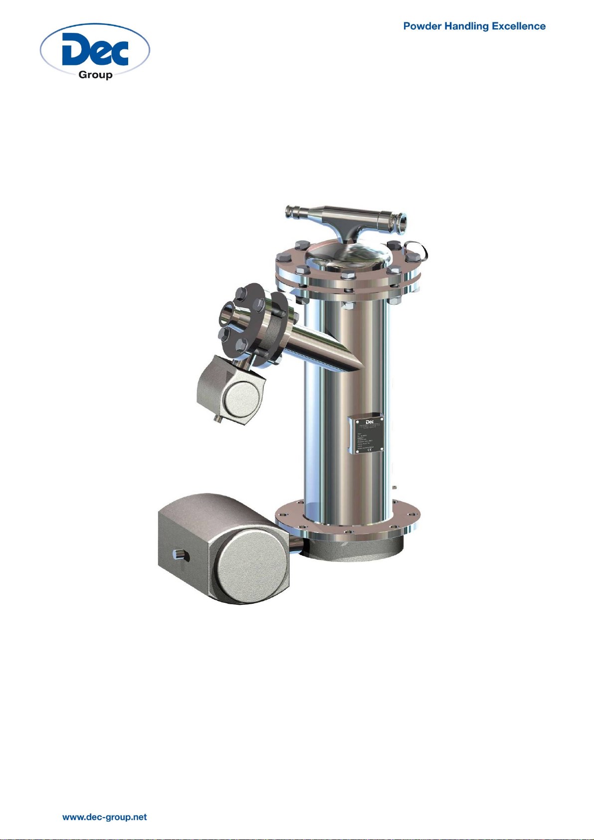
2.7.3 CIP
A liquid separator installed in the upper part of the PTS
body sucks liquids into the system. A float in the main
cover prevents the liquid from entering the vacuum
line.
Optionally, a removable spraying device can also be
mounted on the body of the PTS.

MAN-PTS-GB, Revision 9, BSC, 15-FEB-2017 12/46
Liquid separator
The liquid separator is integrated in the cover of the PTS System. Pressure and vacuum valves are
mounted on a separated tee directly connected to the cover.
The device consists of one main separation chamber with a float in stainless steel. The system
comprises a flange at the bottom and a cap at the top. The guidance (support) of the float is
attached to this cap which is equipped with a tri-clamp to be connected to the T-part.
The float blocks the outlet of the separator in case the liquid would be sucked into the PTS
chamber and pass through the membrane. The float is lifted up by the liquid during the CIP cycle.
When the float reaches a certain level, it is sucked up by the vacuum to an O-ring positioned in
the cap stopping the liquid suction. The vacuum line is then protected against liquid entry.
The vacuum rate required for the suction of liquids is inferior than the one required for powder
transfer. The vacuum line is equipped either with an automatic ball valve which the ball is
perforated perpendicular to the passage of the ball (standard), or with an automatic ball valve
and a by-pass line with a manual valve (optional). When the liquid is sucked, and when the
selector switch is set to “Cleaning”, the automatic valve is closed and the suction is reduced
through the reduced flow orifice.The perforated ball valve or the manual ball valve reduces the
flow rate of about 1/3.
1Compressed air resp. nitrogen flow
2 CIP-Cover
3 Perforated ball valve (standard)
3.1 Perforated ball valve in CIP-position
3.2 Perforated ball valve in product transfer position
4Vacuum

MAN-PTS-GB, Revision 9, BSC, 15-FEB-2017 13/46
5 Bypass with manual ball valve (Option)
6Product inlet
Spraying device (optional)
1 Connection for spraying device, closed with a plug
2 Connection with mounted spraying device
3 Spraying device
The PTS body is equipped with a connection for the installation of a spraying device, which can
be removed after each cleaning. The connection on the side of the PTS is closed by a plug
during the powder transfer.
When the unit has to be cleaned, the installation is stopped and the plug is removed from the
side of the body. The spray nozzle is brought in position and the outlet valve is opened from the
control panel as well as the valve for the cleaning solution supply. The cleaning solutions are
collected in the equipment which is installed below the PTS System.
If the PTS system must be steam sterilized or rinsed by circulation of a liquid, inlet and outlet valves
can be opened simultaneously.
Subsequently, the PTS is dried either by flushing the system with dry gas (if no gas do dry
mechanically byopening the unit).When the cleaning and drying process is completed, the PTS
is already opened to remove the filter and exchange the membrane.

MAN-PTS-GB, Revision 9, BSC, 15-FEB-2017 14/46
2.8 TECHNICAL DATA
This chapter describes the technical data of the system. Other models are also available
according to your specific needs. If you have ordered a special model, see the corresponding
technical data in the appendix to this manual.
2.8.1 DIMENSIONS
The detailed dimensions and materials of the system can be found in the drawings and part lists
of the technical documentation.
2.8.2 POWER SUPPLY/MEDIA
Compressed air (Control, Valves): 5-6 bar
Compressed air/Nitrogen (Filter-cleaning): 3 bar
2.8.3 ENVIRONMENTAL CONDITIONS
The system is only to be operated in areas which fulfil the following conditions:
-Closed buildings, protected from the weather.
-Ambient temperature: +0 to +60 °C.
2.8.4 NOISE EMISSIONS
Noise pressure level LpA < 80 dB(A)
Depending on the circumstances at the place of installation higher sound pressure levels may
be caused.
2.8.5 CLEANING AGENTS
Wet cleaning: Water
Dry cleaning: Vacuum equipment, slightly humid cloths

MAN-PTS-GB, Revision 9, BSC, 15-FEB-2017 15/46
3CONSTRUCTION AND OPERATION
The chamber is the main part of the PTS technology. The PTS filter is located in the upper part of
the chamber, between the body and the cover. The system consists of 4 valves which are
connected to a control system. The valve "product inlet" V1 and the valve "product outlet" V2
are directly mounted on the chamber. The valve connected to the vacuum and the valve
connected to a pressure source are either connected to the PTS cover by a flexible hose or
directly mounted on the PTS cover.
The valves open and close automatically according to a logical sequence in order to alternate
the filling and emptying cycles of the PTS chamber. The system, from its principle, can transfer
products dust-free without changing their homogeneity. It can, furthermore, fill closed vessels
without the introduction of oxygen.
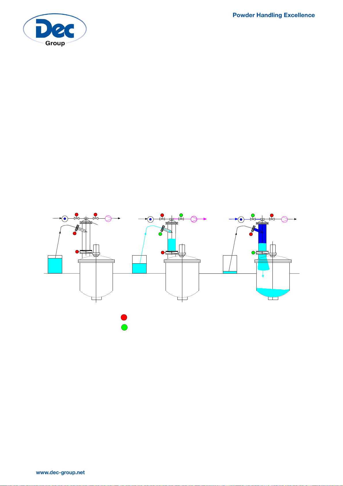
The suction and emptying times and the frequency of the cycles can be easily adjusted
according to the process conditions. The figures below describe the different PTS steps in detail.
In the shutdown position, all the valves
are closed.
At the beginning of the suction phase,
the vacuum valve V3 opens. Vacuum is
created in the PTS chamber by the
vacuum pump connected to valve V3.
VACUUM
PUMP
PRESSURE
POWDER
V1
Valve closed
Valve open
V2
V3
V4
VACUUM
PUMP
PRESSURE
POWDER
V1
Valve closed
Valve open
V2
V3
V4

MAN-PTS-GB, Revision 9, BSC, 15-FEB-2017 16/46
After a predetermined time, the inlet
valve V1 opens. The product is sucked
into the chamber with the vacuum
created by the vacuum pump.
After a given time, when sufficient
powder has been filled into the PTS
chamber,inlet valve V1 closes (the filling
rate is controlled by a timer).
The vacuum valve V3 remains open in
order to evacuate the residual air still
present in the chamber.
When the vacuum valve V3 closes, the
valve V4, which is connected to a
pressure source (compressed gas),
opens. The gas used for the system can
be selected according to the process
conditions. Compressed air or nitrogen is
used in most cases. The residual vacuum
is eliminated by opening the pressure
valve V4, and the chamber is put under
pressure.
The product outlet valve V2 can then
open. The chamber is emptied by the
pressure effect and the product is
introduced into the receiver. The filter is
cleaned in a countercurrent fashion
during the discharge cycle by the
stream of gas. This allows maintaining
the initial suction capacity for the next
cycle. The outlet and pressure valves V2
and V4 close after a given time.
VACUUM
PUMP
PRESSURE
POWDER
V1
Valve closed
Valve open
V2
V3
V4
VACUUM
PUMP
PRESSURE
POWDER
V1
Valve closed
Valve open
V2
V3
V4
VACUUM
PUMP
PRESSURE
POWDER V1 Valve closed
Valve open
V2
V3
V4
VACUUM
PUMP
PRESSURE
POWDER V1 Valve closed
Valve open
V2
V3
V4

MAN-PTS-GB, Revision 9, BSC, 15-FEB-2017 17/46
In most cases, a new suction cycle will immediately restart. However, it may be necessary for
certain processes to introduce a waiting time between each cycle in order to regulate the
transfer capacity. During this waiting time, all valves remain closed.
The logic described above corresponds to the standard operation of the PTS. In case of a
special operating sequence, you will find the corresponding diagram in the technical
documentation.

MAN-PTS-GB, Revision 9, BSC, 15-FEB-2017 18/46
4TRANSPORT AND STORAGE
The PTS system is delivered pre-assembled with the exception of a few components (PTS
chamber, vacuum pump, etc.).
Each component is wrapped in a sheet of protective plastic and packed into a box made of
wood or cardboard. Empty spaces between the components are filled with synthetic chips. A
protective layer of cellophane is wrapped around the entire box.
The box must be carefully handled with a forklift truck or a hydraulic lift. However, there are no
special tools required for handling the equipment.
4.1 INSPECTION AFTER TRANSPORT
Upon receipt of the goods, immediately check the equipment, mainly for completeness and
any damage incurred during transportation.
First check with help of the equipment list, which is included in the technical documentation,
that the supplied equipment is complete. A general drawing of all components of the system
can be also found in the technical documentation.
Missing or damaged parts must be immediately notified to Dec. Please document these defects
immediately by taking pictures and accurate records.
4.2 TRANSPORT AND LIFTING
Size the lifting equipment as indicated by the manufacturer by adding a security margin.
Danger from falling loads!
Do not stand under suspended loads!
Attention to your work colleagues!
Raise the machine or the equipment with a suitable hoist after fixing the slings or chains to
machine components that can withstand such loads.
4.3 STORAGE
The equipment must not be removed from the box if it is stored. If the equipment must be
inspected upon delivery, it has to be repackaged in its original box and the box must once again
be hermetically sealed.
The box must be stored in a closed place, which is cool, dry,well ventilated and does not contain
any chemical agents. In any event, the box should never be stored outside. Nothing may be
placed on top of the box and the box must be easily accessible, so that it won't get damaged
when being handled.
Store the equipment and the supplied material for the installation respecting to a minimum
spacing between each part, without side support or superposed material.

MAN-PTS-GB, Revision 9, BSC, 15-FEB-2017 19/46
Risk of damage to components!
The storage must be done in an enclosed area, dry, temperate, protected from
frost and light. Avoid moisture, high temperatures and dirt.
Depending on the time and the conditions of storage, a special packaging may be necessary.
In all cases, you must check with the manufacturer by describing the conditions and the time of
storage.

MAN-PTS-GB, Revision 9, BSC, 15-FEB-2017 20/46
5ASSEMBLY, CONNECTIONS AND FIRST COMMISSIONING
Risk of damage to components!
Assembly, connections and first commissioning should be performed by qualified
personnel with relevant experience. Errors could lead to dangerous situations and
result in considerable material damage.
According to the ATEX 137 guideline and the regulations on safe operation, the
operator must ensure a safe working environment.
It is forbidden to modify the construction or to carry out welding work on the PTS
system without prior consent of the manufacturer as well as to increase the power
supply to the system.
5.1 MECHANICAL ASSEMBLY
The equipment doesn’t require any specific assembly. Nevertheless, some verification is
necessary:
-All screws and all nuts are properly tightened on the PTS system;
-The bolt connection is tightened according to the torque required by the maximum
pressure of the system.
In most cases, the PTS system is directly mounted on your equipment. Your connecting flange
must therefore correspond to the flange size of the PTS chamber which is given by the outlet
valve V2 (see table with technical data). The PTS connecting flanges correspond usually to DIN
PN 10 or ANSI 150 standards. The flange type must be specified in the order of your PTS system.
The types and dimensions of the various connections are given in the assembly drawing included
in the technical documentation.
5.2 INSTALLATION
1) Install the outlet valve V2 on the connecting flange of your installation. The valve actuator
can be positioned differently according to the space available and the accessibility of the
system;
2) Fix the butterfly valve between the PTS chamber and the equipment flange. The orientation
of the chamber is determined by the position of the inlet tube;
The butterfly valves supplied with the PTS system are tight when correctly mounted
and, therefore, do not require any supplementary gaskets.
This manual suits for next models
1
Table of contents
Popular Industrial Equipment manuals by other brands

epro
epro Combi Machine user manual

TRAILPARTS
TRAILPARTS hygo3 installation guide

SCHUNK
SCHUNK TANDEM KSH3 Assembly and operating manual

Georg Fischer
Georg Fischer Signet 2630-X instructions

Altra Industrial Motion
Altra Industrial Motion Warner Electric PB-120 installation instructions

Dynapac
Dynapac F1000T operation & maintenance


Georg Fischer
Georg Fischer ALUPEX Gasystem manual

cashco
cashco CA1 Installation, operation & maintenance manual

Larzep
Larzep SM INSTRUCTIONS & MAINTENANCE SHEET

Flott
Flott TS 150 SW operating instructions

Crane
Crane Barnes 3SE-DS Series Installation and operation manual

SUHNER MACHINING
SUHNER MACHINING BEM 20 Technical document