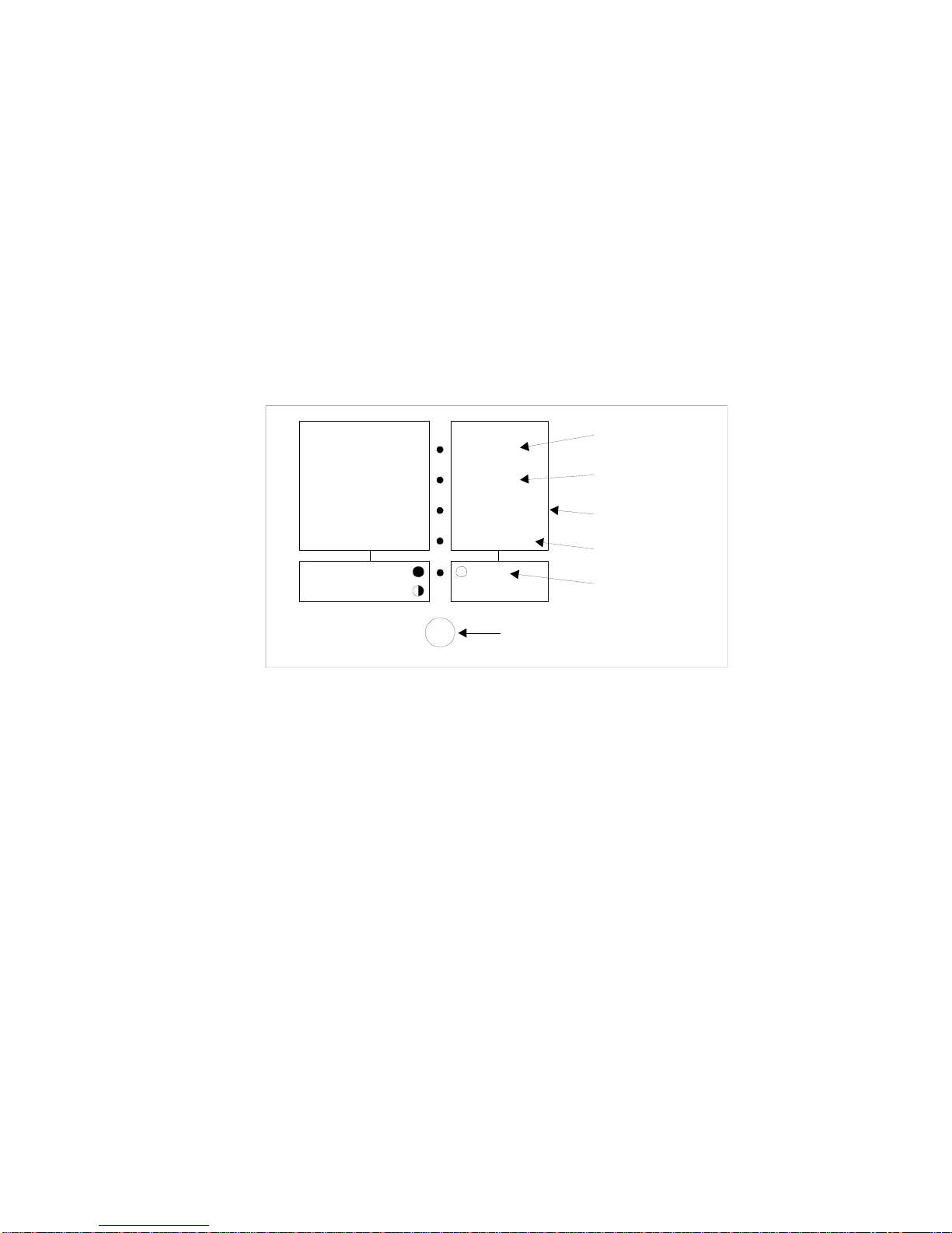
STATUS & ALARM INDICATORS - LED 5 (green) OFF
When power is first applied LED 1 should flash.
When LED 5 is OFF, this indicates the LED (1) – (4) is showing the inverters STATUS, as per written
notation to the right of the LED’s. In this mode there are no adjustments to be made.
LED 1 Flashing indicates the WM1200 is in Auto Start mode, this indicates that no power is being
drawn from the inverter so it has gone to SLEEP to save power. If no power is used within 12 minutes,
LED 1 will flash at a slower rate therefore saving more power.
LED 1 Stays ON, the inverter has been commanded to provide power to the load (e.g. a light switch
has been turned on) so it has gone from SLEEP mode to ON. Once the load has been removed (e.g. the
light switch is turned off) the inverter will wait 10 seconds and return to SLEEP mode.
•It is good practice to have your WM1200 in SLEEP mode as often as possible. When the
WM1200 is in SLEEP mode it uses 0.055 amps from the battery, when the inverter is in the ON
mode it uses at least 0.6 amps from the battery.
The amount of power required to go from SLEEP to ON is adjustable and is described on below.
LED 2, AC Overload should normally remain OFF. If the inverter shuts down due to too much AC
load being drawn from it then LED 2 will come ON. The WM1200 will remain in this condition for 2
minutes after the AC load has been decreased to a safe level. LED 2 will flash if the inverter shuts down
due to “time to shutdown”, see page 11.
•If the inverter remains in this condition after two minutes, the main DC Power Switch should be
turned OFF and then back ON.
LED 3 DC Volts Low / High should normally remain OFF. If the inverter shuts down because the
battery volts are too high then this LED will come ON. It will remain ON until normal battery volts are
restored.
•If the inverter shuts down due to not enough battery volts, then LED 3 will flash.
•LED 3 will continue to flash until the battery volts have risen sufficiently. In this case, charge the
battery by starting the vehicle or using a battery charger.
The low voltage point that the inverter will cut out is adjustable to suit your particular battery.
LED 4, Temperature Overload should normally remain OFF. If the inverter shuts down due to the
heatsink getting too hot, then this LED will come ON. If the inverter shuts down due to the transformer
getting too hot, then this LED will FLASH. The inverter will remain shut down until the temperature
has lowered to a safe level; the inverter will then come back ON.
•If this LED is coming on regularly, either reduce the amount of load on the inverter or try to move
the inverter to a cooler location.
DEMAND START ADJUST - LED 5 (green) ON
It is sometimes necessary to adjust the auto start sensitivity to overcome what is called “Phantom
Loads”. A phantom load is a load that tricks the inverter into thinking it should be ON instead of in
SLEEP mode.
The wiring of a house or a portable stereo system in standby are good examples of a phantom load.
These loads serve no purpose but can increase battery drain by bringing the inverter ON. Hold the
Mode button down, (approximately 1 second), LED 5 will turn ON indicating you are ready to adjust
this setting. The WM1200 will leave the factory with a setting of 4 Watts. Now press the Mode button
until the desired value is sought. LED’s 1 – 4 will return to Status Indication after 10 seconds if a key is
not pressed.
•Each press of the Mode Button will increment the Demand Start Level. The adjustment starts from
the previously stored setting.
6