Selleys S39E User manual

OPERATING MANUAL
SELLEYS S39E AIRLESS SPRAYPACK

OPERATING MANUAL – SELLEYS S39E
CONTENTS
1. SAFETY INFORMATION
1.1 General Safety Precautions
1.2 Specific Safety Hazards and Precautions
1.3 Earthing Instructions
2. COATINGS
2.1 Suitable Coatings
2.2 Preparation of Coating Materials
2.3 Viscosity
2.4 2-component Coating Materials
2.5 Coatings Containing Abrasive Materials
3. EQUIPMENT
3.1 Technical Data
3.2 Main Components
4. OPERATING INSTRUCTIONS
4.1 Setup
4.2 Startup
4.3 Pressure Relief Procedure
4.4 Installation of Spray Tip
4.5 Clearing Spray Tip Clogs
4.6 Before Spraying the Coating Material
4.7 Method of Spraying
4.8 Handling the High-Pressure Hose
4.9 In Case of Interrupted Operation
5. CLEANING AND MAINTENANCE
5.1 Cleaning and Shutting Down
5.2 Cleaning the Airless Spray Gun
5.3 Disassembly of the Gun Filter
5.4 Assembly of the Gun Filter
6. MALFUNCTIONS
6.1 Corrective Measures for Common Malfunctions
6.2 Error Codes
7. PARTS AND ASSEMBLY

OPERATING MANUAL – SELLEYS S39E
3
WARNING
This unit is capable of extremely high spraying pressures that can cause serious and/or minor
injury by injection and extensive damage to property.
IMPORTANT
All replacement parts and accessories should ONLY be purchased from SELLEYS or an
authorised distributor of SELLEYS equipment. Servicing should ONLY be carried out by SELLEYS
or an authorised distributor of SELLEYS equipment. If these conditions are not met, the operator
assumes all liability for injury and property damage arising from the use of this unit.
1. SAFETY INFORMATION
Please read the following important information carefully.
The following symbols indicate specific types of safety hazards.
Indicates a potential hazard that may cause serious injury to the operator or
loss of life.
Indicates a potential hazard that may cause minor injury to the operator or
to the equipment.
Indicates important information.

OPERATING MANUAL – SELLEYS S39E
4
1.1 GENERAL SAFETY PRECAUTIONS
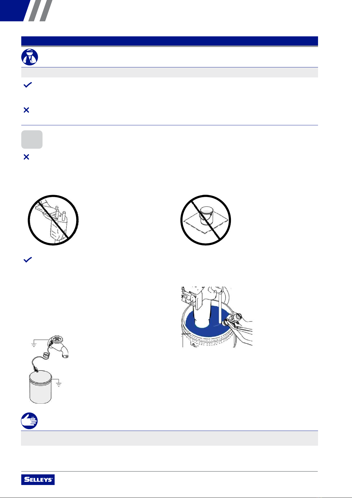
NEVER
• use the spray gun without the safety guard in place
• operate faulty units or use faulty accessories
• attempt to repair a damaged hose
• leave this equipment unattended
• move the unit when it is running
• spray outside on windy days
ALWAYS
• ensure that this unit is properly earthed
• ensure that the power cord, air hose and spray hoses are optimally routed to minimise slip, trip and fall hazards
• immediately and thoroughly clean up all material and solvent spills to prevent slip hazards
• follow the material manufacturer’s instructions for safe handling of coating materials
• unplug the cord from the outlet before cleaning, maintaining or repairing this unit
• keep the power cord plug in sight during use to prevent accidental shutdowns and startups
• wear ear protection to protect against possible hearing loss from the noise produced by this unit, which can exceed 85 dB(A)
• keep this unit out of reach of children, unqualified adults and animals
• comply with local codes regarding ventilation, fire prevention, and operation
1.2 SPECIFIC SAFETY HAZARDS AND PRECAUTIONS
SAFETY PRECAUTIONS TO PREVENT INJECTION INJURY
WARNING
Serious risk of injection injury. This equipment produces a high-pressure stream that can pierce the skin and subcutaneous
tissues, resulting in severe injury and even possible amputation.
IMPORTANT
The maximum operating range of the unit is 21 bar (22.1 MPa, 3200 PSI) fluid pressure.
NEVER
• put your fingers, hands or any other parts of your body into the spray jet
• point the spray gun at yourself or anyone else (including animals)
• allow the fluid stream to come into contact with any part of your body
• allow any leak in the fluid hose to come into contact with any part of your body
• put your hand in front of the gun
NOTE: Gloves do not provide full protection against injection injury.
• use a spray gun without both a working trigger lock and trigger guard in place
ALWAYS
• ensure that the gun trigger is locked, the fluid pump is shut o, and all pressure is released before servicing, cleaning the tip
guard, changing tips, or leaving the unit unattended
NOTE: Turning o the engine will not release the pressure. The PRIME/SPRAY valve or pressure bleed valve must be turned to their appropriate
positions to relieve system pressure.
• ensure that the tip guard remains in place during spraying
• remove the spray tip before flushing or cleaning the system
• carefully check the paint hose for leaks before each use, as even small leaks can cause injection injury
• ensure that all accessories, including but not limited to spray tips, guns, extensions and hose, are rated at or above the
maximum operating pressure range of the sprayer
IMPORTANT MEDICAL INFORMATION
Injection injury is a traumatic injury that requires immediate medical attention. Any laceration of the skin, no matter how minor
it seems, should not be treated as a simple cut. Fully inform the medical team about the coatings or solvents involved, as some
coatings are toxic when injected directly into the bloodstream. For serious injuries, a plastic surgeon or reconstructive hand
surgeon should be consulted.

OPERATING MANUAL – SELLEYS S39E
5
SAFETY PRECAUTIONS TO PREVENT EXPLOSIONS AND FIRE
WARNING
This equipment produces a high-pressure stream that can pierce the skin and subcutaneous tissues, resulting in severe injury
and even possible amputation.
NEVER
• use plastic drop cloths or enclose the spray area with plastic sheets, as plastic can cause static sparks
• smoke in the spray area
• use any materials with a flashpoint lower than 21°C (70°F)
NOTE: Flashpoint is the temperature at which a fluid can produce sucient vapours to ignite.
ALWAYS
• ensure that the spray area is well-ventilated to prevent the build-up of flammable vapours
• avoid all ignition sources such as static electricity sparks, electrical appliances, flames, pilot lights, hot objects, and sparks from
connecting and disconnecting power cords and/or working light switches
• flush the unit into a separate metal container, at the lowest possible pump pressure and with the spray tip removed
• hold the gun firmly against the side of the container to prevent static sparks
• have a fire extinguisher nearby
• place the sprayer at a minimum of 6.1 metres (20 feet) from the surface to be sprayed, extending the hose if necessary. Since
flammable vapours are often heavier than air, the floor area must be well ventilated. The pump contains arcing parts that emit
sparks, which can ignite vapours.
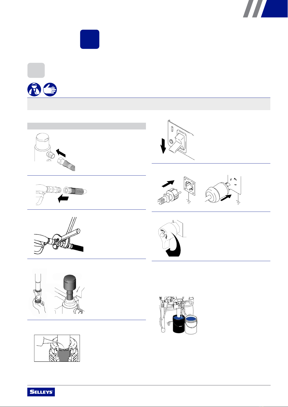
• ensure that the equipment and objects in and around the spray area are properly grounded to prevent static sparks
• ensure that you are using a conductive or earthed high pressure hose
• ensure that the gun is earthed through the hose connection
• ensure that the power cord is connected to a grounded circuit
• ensure that the unit is connected to an earthed object such as a water pipe, steel beam, or other electrically earthed surface, via
the green earthing wire
• strictly follow the material and solvent manufacturer’s warnings and instructions, and read the coating material’s MSDS
(Material Safety Data Sheet) and technical information before use
SAFETY PRECAUTIONS TO PREVENT EXPLOSIONS DUE TO INCOMPATIBLE MATERIALS
WARNING
Serious risk of explosions due to incompatible materials. Accidental explosions due to incompatible materials can cause serious
injury and/or extensive damage to property.
NEVER
• use materials that contain bleach or chlorine
• use halogenated hydrocarbon solvents such as methylene chloride and 1,1,1-trichloroethane
NOTE: These substances are not compatible with aluminium and may cause an explosion. If you are in any doubt over a material’s compatibility
with aluminium, check with your coating supplier.
SAFETY PRECAUTIONS TO PREVENT HARM FROM TOXIC VAPOURS
WARNING
Vapours from paints, solvents, insecticides, and other materials can be harmful in the event of inhalation or contact with any part
of the body. Symptoms include severe nausea, fainting and poisoning.
ALWAYS
• use a respirator or mask
• wear protective eyewear
• wear protective clothing
OPERATING MANUAL – SELLEYS S39E
6
• operate this unit unless you are sure that it has been
properly earthed
• modify the earthing plug
• use an adapter with this equipment
ALWAYS
• ensure that the earthing plug is plugged into an outlet that
has been properly installed and earthed in accordance with
local codes
• seek the advice of a qualified electrician if you need a
new outlet installed to fit the earthing plug, do not fully
understand these earthing instructions, or are unsure as to
whether this unit is properly earthed
• use grounded metal pails for solvent- and oil-based fluids
• connect the ground wire from the metal pail to a true earth
ground such as a water pipe
SAFETY PRECAUTIONS TO PREVENT HARM FROM MOVING PARTS
WARNING
Moving parts can pinch, cut or amputate fingers and other body parts. Furthermore, equipment can start without warning.
ALWAYS
• keep clear of moving parts
• follow the Pressure Relief Procedure and disconnect all power sources before checking, moving or servicing the equipment
NEVER
• operate equipment with protective guards or covers removed
1.3 EARTHING INSTRUCTIONS
NEVER
WARNING
Incorrect installation of the earthing plug can result in electric shock. If you need to repair or replace the cord or plug, do not
connect the green earthing wire to either blade terminal.
• if required, use 1,5 mm2grounded extension cords,
measuring a maximum of 30m in length
• use 3/8 x 50 ft (minimum), non-wire braid hose
• place pail on grounded surface such as concrete
• hold spray gun against grounded metal pail when flushing or
relieving pressure to maintain ground
• place pail on non-conductive materials, which will isolate
pail from ground
OPERATING MANUAL – SELLEYS S39E
7
IMPORTANT
The wire with insulation, which has a green outer surface with or without yellow stripes, is the earthing wire. It must be
connected to the earthing pin.
Use of an undersized cord causes a drop in line voltage, loss of power and overheating.
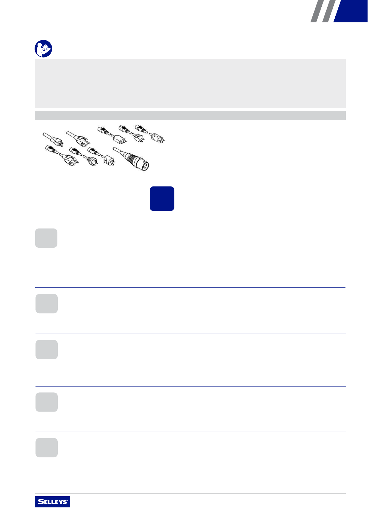
A list of the materials used in the construction of this unit is available upon request for the purpose of determining compatibility
with coating materials.
NOTE: All sprayer cords include a ground wire to reduce the risk of static and electric shock.
2. COATINGS
Please read the following important information carefully.
2.1 SUITABLE COATINGS
This unit is suitable for the application of:
• dilutable lacquers and paints
• coatings containing solvents
Do not spray coatings other than those listed above without the prior approval of SELLEYS or the authorised distributor of this unit.
• 2-component coating materials
• dispersions
• latex paints
2.3 VISCOSITY
This unit is able to process highly viscous coating materials of up to around 20,000 mPa-s.
Highly viscous coating materials can be diluted according to the manufacturer’s instructions.
When preparing two-component coating materials for spraying, follow the manufacturer’s instructions and do not skimp on the
mixing/processing time. While the components are processing, thoroughly rinse and clean the unit with suitable cleaning agents.
Coatings that contain sharp-edged aggregates and additional materials cause intense wear and tear on this unit’s parts, including
its valves, high-pressure hose, spray gun and tip.
Use of abrasive coatings may shorten the working life of this unit.
2.4 2-COMPONENT COATING MATERIALS
2.5 COATINGS CONTAINING ABRASIVE MATERIALS
Always filter and stir the coating material before application. To prevent downtime, make sure that no air bubbles are introduced,
especially when stirring the coating material with motor-driven agitators.
2.2 PREPARATION OF COATING MATERIALS

OPERATING MANUAL – SELLEYS S39E
8
3. EQUIPMENT
Please read the following important information carefully.
3.1 TECHNICAL DATA
Motor Output 4.0KW
Flow Rate (LPM) 8.3L
Min./Max. Nozzle Size 0.045”
Max. Pressure 20 mPa
Weight 68kg
3.2 MAIN COMPONENTS
A
DD
E
B
C
DF
NO. PRODUCT NAME
A ON/OFF switch
B Pressure control knob
C Relief valve
NO. PRODUCT NAME
D Fluid outlet
E Return hose
FSuction Tube
OPERATING MANUAL – SELLEYS S39E
9
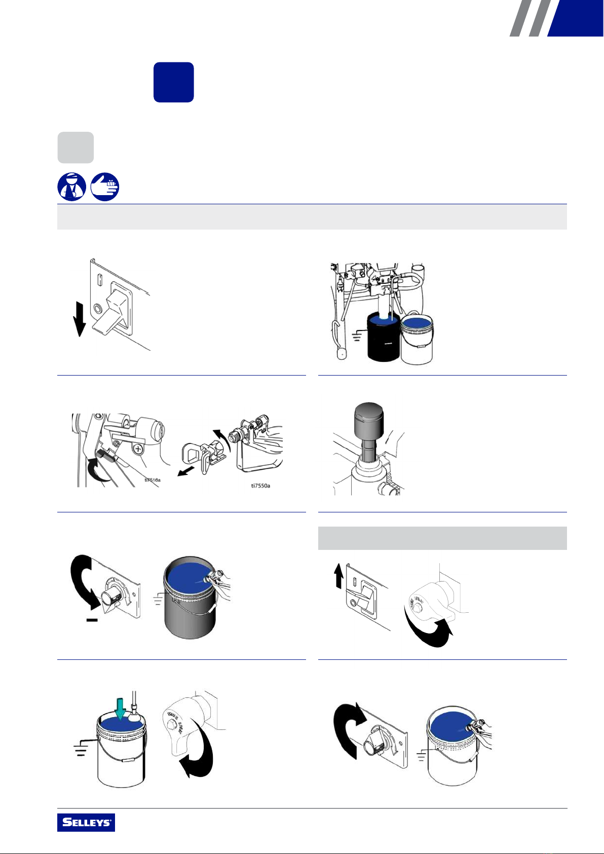
4.1 SETUP
WARNING
Serious risk of explosions due to incompatible materials. Accidental explosions due to incompatible materials can cause serious
injury and/or extensive damage to property.
4. OPERATING INSTRUCTIONS
Please read the following important information carefully.
1. Connect 15m (50 ft) airless hose to sprayer and tighten
securely
NOTE: Remove adapter fitting for 13mm (1/2 in.) hose.
5. Fill throat packing nuts with separating oil to prevent
premature packing wear. Do this each time you spray.
2. Install airless hose to the fluid inlet of the spray gun
3. Tighten securely
6. Turn power OFF
8. Turn the relief valve to "PRIME" position
7. Plug power supply cord into a properly grounded electrical
outlet
9. Place suction tube into a metal pail partially filled with
residual water. Attach ground wire to pail and to true earth
ground (see Earthing Instructions). Perform steps 1 – 5
of Startup to flush out storage oil shipped in sprayer. Use
water to flush water-based paint and appropriate solvent to
flush oil-based paint and storage oil.
4. Remove inlet strainer and suction filter when spraying
plaster materials
OPERATING MANUAL – SELLEYS S39E
10
4.3 PRESSURE RELIEF PROCEDURE
4.2 STARTUP
WARNING
Serious risk of explosions due to incompatible materials. Accidental explosions due to incompatible materials can cause serious
injury and/or extensive damage to property.
1. Turn pressure control knob to "minimum" 5. Trigger the spray gun, whilst increasing the pressure
control knob, if neccessary
6. Inspect for leaks. If leaks occur, perform Pressure Relief
Procedure. Tighten fittings. Perform Startup steps 1 - 5.
If no leaks, proceed to step 6.
7. Place suction tube into the container of material
8. Trigger gun again into flushing pail until paint appears.
Move gun to paint pail and trigger for 20 seconds. Set gun
safety ON. Assemble tip and guard.
2. Turn power ON
3. Increase pressure to start motor and allow fluid to
circulate through return hose for 15 seconds. Decrease
pressure control knob to "minimum".
4. Turn relief valve to "SPRAY" position
Follow these steps carefully.
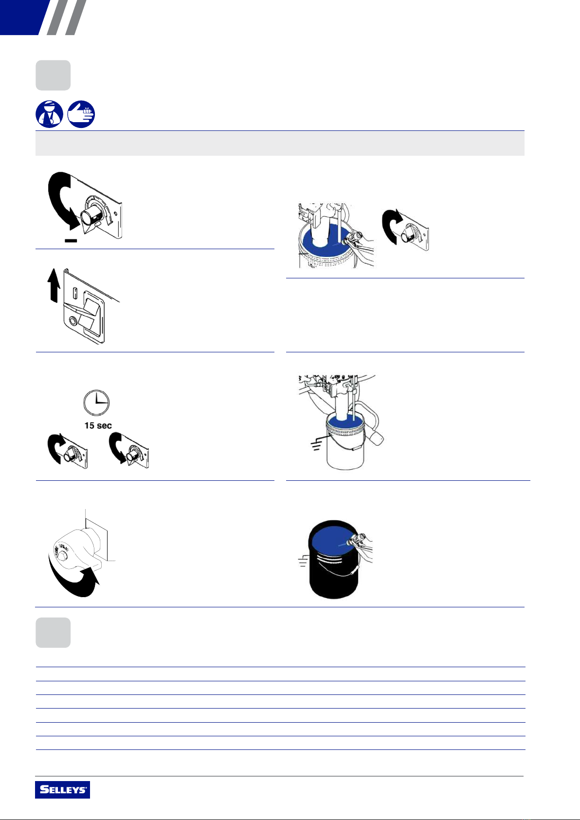
1. Immerse the suction tube and return hose in a container, filled with a suitable cleaning agent
2. Turn the pressure control knob counter-clockwise to minimum pressure
3. Turn the relief valve and set to "PRIME" position
4. Wait until the cleaning agent discharges from the return hose
5. Turn the relief valve and set to "SPRAY" position
6. Pull the trigger of the spray gun
7. Spray the cleaning agent from the unit into a container
OPERATING MANUAL – SELLEYS S39E
11
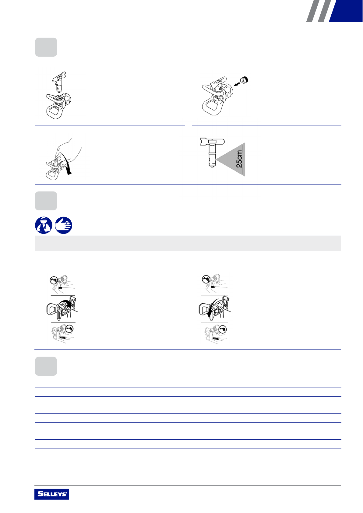
3. Install assembled spray tip and nozzle holder in spray gun 4. Install appropriate spray tip for your material
1. Release trigger, put safety ON. Rotate Spray Tip. Take
safety OFF. Trigger gun to clear clog. Never point gun at
your hand or into a rag!
2. Put safety ON. Return Spray Tip to original position. Take
safety OFF and continue spraying.
11
4.3
1. Insert tip cylinder into guard (arrow points forward).
2. Install Nozzle Seal (curved side in) into housing.
3. Install assembled tip and guard onto spray gun.
4. Install appropriate tip for your material.
4.4 Clear pray Tip Clogs
1. Release trigger, put safety ON. Rotate Spray Tip.
Take safety OFF. Trigger gun to clear clog. Never
point gun at your hand
or into a rag!
2. Put safety ON. Return Spray Tip to original position.
Take safety OFF and continue spraying.
4.6 BEFORE SPRAYING THE COATING MATERIAL
Follow these steps carefully.
1. Turn the pressure control knob counter-clockwise to minimum pressure
2. Turn the relief valve and set to "PRIME" position
3. Switch the unit ON
4. Wait until the coating material discharges from the return hose
5. Turn the relief valve and set to "SPRAY" position
6. Trigger the spray gun and spray into a container until the coating material exits the spray gun continuously
7. Increase the pressure by slowly turning the pressure control knob clockwise
8. Check the spray pattern and increase the pressure until the desired atomisation is attained
9. The unit is ready to spray
1. Insert spray tip into nozzle holder (arrow points forward) 2. Insert nozzle seal (curved side in) into housing
4.5 CLEARING SPRAY TIP CLOGS
WARNING
Serious risk of explosions due to incompatible materials. Accidental explosions due to incompatible materials can cause serious
injury and/or extensive damage to property.
4.4 INSTALLATION OF SPRAY TIP

OPERATING MANUAL – SELLEYS S39E
12
2. Trigger the gun AFTER starting the stroke
3. To ensure even application:
• keep your arm moving
at a constant speed
• keep the spray gun
perpendicular to the
surface
• keep the spray gun at
a constant distance
of 25 to 30cm from
the surface
• overlap each stroke
by about 30%
4. Release the gun BEFORE ending the stroke
NOTE: Gloves do not provide full protection against injection injury.
IMPORTANT
If very sharp edges or streaks appear on the coated surface, increase the operating pressure or dilute the
coating material.
4.8 HANDLING THE HIGH-PRESSURE HOSE
Avoid sharp bending or kinking of the high-pressure hose. The smallest bending radius amounts to about 20cm.
Do not drive over the high-pressure hose, and avoid contact with sharp objects and edges.
WARNING
Defective high-pressure hoses can leak and cause serious injection injury. Replace defective high-pressure hoses immediately.
Never attempt to repair a defective high-pressure hose.
4.9 IN CASE OF INTERRUPTED OPERATION
Follow these steps carefully.
1. Turn the relief valve and set to "PRIME" position
2. Switch the unit OFF
3. Turn the pressure control knob counter-clockwise to minimum pressure
4. Pull the trigger of the spray gun in order to release the pressure from the high-pressure hose and spray gun
5. Secure the spray gun
6. Leave the suction tube (or the suction hose and return hose) immersed in the coating material, or in a cleaning agent
IMPORTANT
If a fast-drying or two-component coating material is used, ensure that the unit is rinsed with a suitable cleaning agent within the
processing time.
25 – 30cm 25 – 30cm
4.7 METHOD OF SPRAYING
WARNING
Never trigger the gun unless the tip is completely turned to either the spray or the unclog position. Always engage the gun trigger
lock before removing, replacing or cleaning the spray tip.
Follow these steps carefully.
1. Ensure that the nozzle holder guard is in place
25 – 30cm 25 – 30cm
OPERATING MANUAL – SELLEYS S39E
13
5. CLEANING AND MAINTENANCE
Please read the following important information carefully.
A. Turn power OFF. Wait 30 seconds for power to dissipate. 1. Do Steps A - D first. Remove suction tube from paint and
place in flushing fluid.
C. Turn the pressure control knob to "minimum", and trigger
the gun to release pressure
B. Lock gun trigger safety. Remove nozzle holder and spray tip. 2. Unscrew the filter cap, and clean the strainer filter
D. Put the return hose in a container and turn the relief valve
to "PRIME" position
3. Switch power ON, and turn the relief valve to "SPRAY" position
NOTE: Use water for water-based material and appropriate solvent
for oil-based material.
4. Increase pressure slowly. Hold gun against the paint
container. Unlock the trigger, and flush the gun until the
flushing fluid appears.
5.1 CLEANING AND SHUTTING DOWN
WARNING
Serious risk of explosions due to incompatible materials. Accidental explosions due to incompatible materials can cause serious
injury and/or extensive damage to property.

OPERATING MANUAL – SELLEYS S39E
14
5. Move gun to waste pail, hold gun against pail, trigger gun
to thoroughly flush system. Release trigger and put trigger
safety ON.
9. Turn the relief valve to "PRIME" position, and ensure the
pressure control knob is set to "minimum". Unplug the unit
from the power source.
6. Turn the relief valve to "PRIME" position and allow the
flushing fluid to circulate and clean the return hose 10. Remove filters from gun and sprayer, if installed. Clean
and inspect. Install filters.
7. Remove the suction tube and allow the unit to run and
drain the flushing fluid
11. If flushing with water, flush again with mineral spirits, or
a suitable product, to leave a protective coating to prevent
freezing or corrosion
8. Turn the relief valve to "SPRAY" position. Trigger the gun
into the flushing pail. Switch OFF power. 12. Wipe sprayer, hose and gun with a rag soaked in water or
mineral spirits
IMPORTANT
The container must be earthed in case of coating materials that contain solvents.
13
5. Move gun to waste pail, hold gun against pail,
trigger gun to thoroughly flush system. Release
trigger and put trigger safety ON.
6. Turn prime valve down and allow flushing fluid to cir-
culate for 15 seconds to clean drain tube.
7. Raise pump above flushing fluid and run sprayer for
15 to 30 seconds to drain fluid.
8. Close drain valve. Trigger gun into flushing pail to
purge fluid from hose. Turn power OFF.
9. Open prime valve. Unplug sprayer.
10. Remove filters from gun and sprayer, if installed.
Clean and inspect. Install filters.
11. If flushing with water, flush again with mineral spirits,
or Pump Armor, to leave a protective coating to pre-
vent freezing or corrosion.
12. Wipe sprayer, hose and gun with a rag soaked in
water or mineral spirits.
OPERATING MANUAL – SELLEYS S39E
15
5.4 ASSEMBLY OF THE GUN FILTER
Follow these steps carefully.
1. Place the gun filter (Figure 1.3) with the long cone pointing up into the gun housing
2. Screw the grip (1.2) into the gun housing and tighten
3. Slot in the protective guard (1.1)
1
3
2
IMPORTANT
Replace the gun filter if it is clogged or faulty.
Figure 1
5.2 CLEANING THE AIRLESS SPRAY GUN
Follow these steps carefully.
1. Rinse the airless spray gun with a sucient amount of a suitable cleaning agent
2. Thoroughly clean the tip with a sucient amount of a suitable cleaning agent until all unused coating material has been removed
3. Thoroughly clean the outside of the airless spray gun
5.3 DISASSEMBLY OF THE GUN FILTER
Follow these steps carefully.
1. Pull the protective guard (Figure 1.1) forward with moderate force
2. Unscrew the grip (1.2) from the gun housing and remove the gun filter (1.3)

OPERATING MANUAL – SELLEYS S39E
16
6. MALFUNCTIONS
Refer to the chart below for instructions on how to correct common malfunctions.
6.1 CORRECTIVE MEASURES FOR COMMON MALFUNCTIONS
TYPE OF MALFUNCTION POSSIBLE CAUSES CORRECTIVE MEASURES
A. Motor works but pump does not
work. There is no error code
displayed.
1. Connecting rod is worn or damaged 1. Replace the connecting rod
B. The motor does not start.
Error code E-XX is displayed.
1. Piston rod is stuck due to dry paint
2. Connecting rod/piston rod is damaged
and/or stuck
1. Replace worn or damaged parts
C. The motor does not start. There
is no error code displayed.
1. Gun/nozzle is clogged
2. Pressure setting is too low
3. Filter is clogged
4. High pressure hose is clogged
1. Clean the gun/nozzle
2. Turn the pressure control knob clockwise
to increase the pressure
3. Clean the filter
4. Clean or replace the high pressure hose
D. Pump output is low 1. Pressure setting is too low
2. Filter is clogged
3. Piston rod/suction valve ball is not
in place
4. Pump packing is worn or damaged
5. Gun/nozzle is clogged
6. High pressure hose is clogged or its
diameter is too small
1. Turn the pressure control knob
clockwise to increase the pressure
2. Clean the filter
3. Clean or replace the ball or seat
4. Replace the packing set
5. Clean the gun/nozzle
6. Clean or replace the high pressure hose
with one of a sucient diameter
E. Paint residue in the pump body
lock nut
1. Lock nut has loosened
2. Upper packing is worn or damaged
3. Piston rod is worn or damaged
1. Remove the nut, clean it and re-install it
2. Replace the upper packing
3. Replace the piston rod
F. Paint is discharged
intermittently
1. Air is present in the pump body,
filter assembly or high pressure hose
2. Nozzle is partially clogged
3. Insucient supply of paint
1. Ensure that the connecting pipe is firmly
connected and continue to trigger the
spray gun until air is discharged
2. Clean the nozzle
3. Add more paint to the paint pail
G. Pump works but paint is not
being discharged
1. Air intake valve is leaking
2. Pump seal(s) are worn
3. Paint is too thick
1. Turn the return valve to the return
position until the return pipe has material
flowing out continuously
2. Check to determine if the sealing ring in
the intake valve is worn or damaged, and
the intake valve is loose. If so, replace the
seal(s) and lock the intake valve.
3. Thin the paint according to the
manufacturer’s instructions
H. Sprayer works but display is
blank
1. Display has a loose connection of fault 1. Check and tighten the connections, and
replace the display if necessary

OPERATING MANUAL – SELLEYS S39E
17
6.2 ERROR CODES
ERROR CODE ERROR DESCRIPTION CONDITIONS MAINTENANCE ADVICE
ERR_1 Hardware overcurrent
protection
Hardware overcurrent circuit
signal is detected
1. Switch power OFF and ON
2. Replace circuit board
3. Replace electric motor
ERR_2 Software detects that the motor
current is high
The software detects the
motor current is high
1. Switch power OFF and ON
2. Replace circuit board
3. Replace electric motor
ERR_3 Bus-bar voltage is high The input voltage is high 1. Check that input voltage is
not more than 260VAC
2. Replace circuit board
ERR_4 Bus-bar voltage is low The input voltage is low 1. This feature is temporarily
disabled
ERR_5 Abnormal motor hall The three halls of the motor
appear at high level or low level
1. Check that the hall terminal
is tightly fitted into the
circuit board
2. Replace circuit board
3. Replace electric motor
ERR_9 Chip memory error alarm An error occurred while data
is stored in the chip
1. Replace circuit board
ERR_10 Motor current amplifier error The internal operational
amplifier circuit is abnormal when
the motor is not running
1. Replace circuit board
ERR_11 High pressure error The output circuit voltage of
the pressure sensor is high
1. Reduce pressure
ERR_12 The motor is protected when
the equipment has no pressure
A protection mechanism when the
motor is running continuously for
one minute during return phase
1. Switch power OFF and ON
ERR_13 Chip ID error Abnormality was detected
after powering ON
1. Replace circuit board
ERR_14 Starter motor stall protection The motor is blocked or
not running
1. Check that the UVW
connection of the motor
is intact
2. Replace circuit board
3. Replace electric motor
ERR_15 Pressure sensor failure Detected abnormal signal
of pressure sensor
1. Check that the pressure
sensor is well connected
2. Replace pressure sensor
3. Replace circuit board
ERR_16 Communication check
code error
The chip indicated a checksum
error during internal communication
1. Replace circuit board
ERR_17 Abnormal pressure feedback The pressure estimated by
the software diers from the
actual pressure
1. Check that the pressure
sensor is well connected
2. Replace pressure sensor
3. Replace circuit board
ERR_18 Communication failure No communication signal
is received in the chip
1. Replace circuit board
OPERATING MANUAL – SELLEYS S39E
18
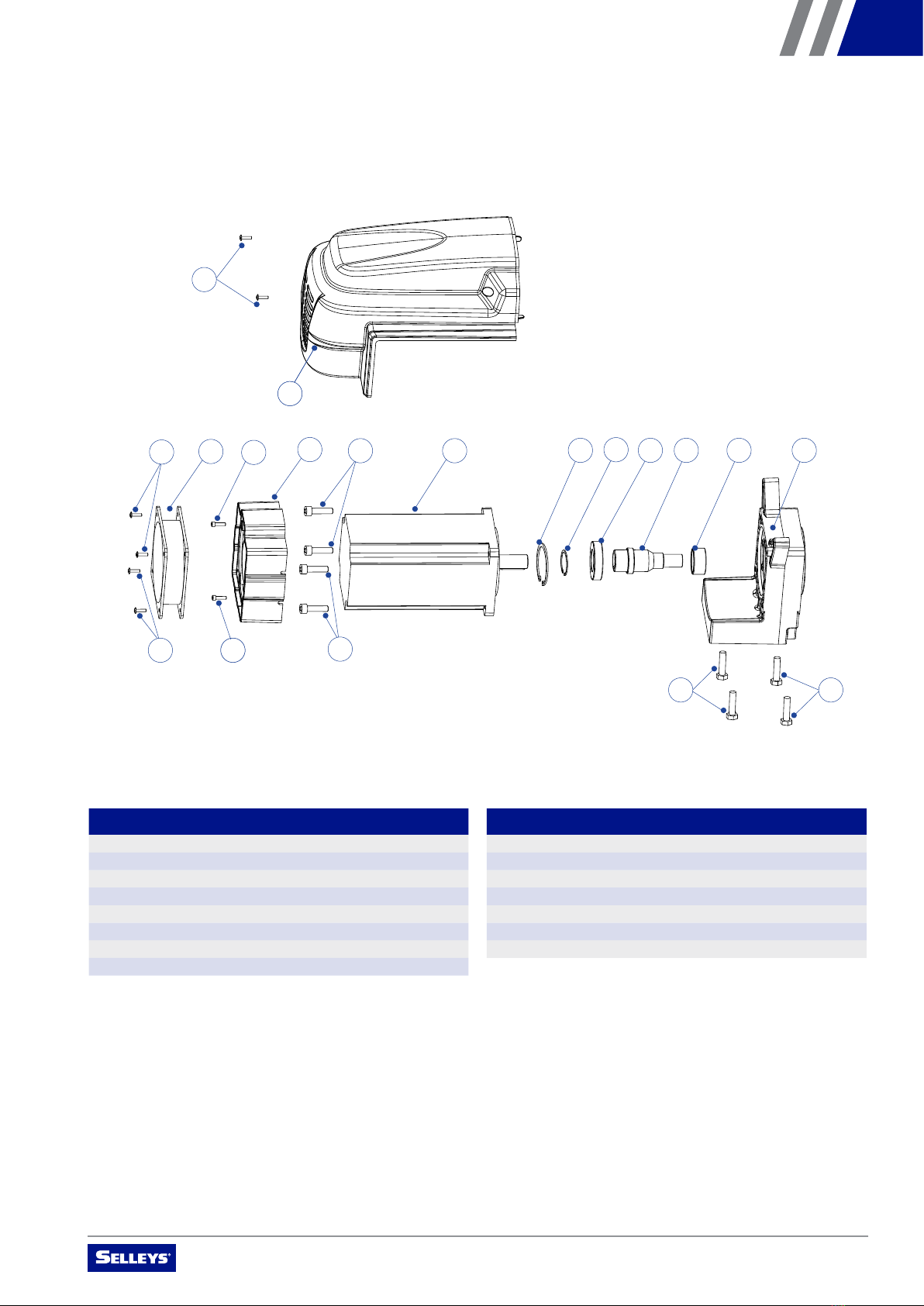
1002
1005 1005
1006
1006
1007
1003
1003
1004
1004
1001
1002
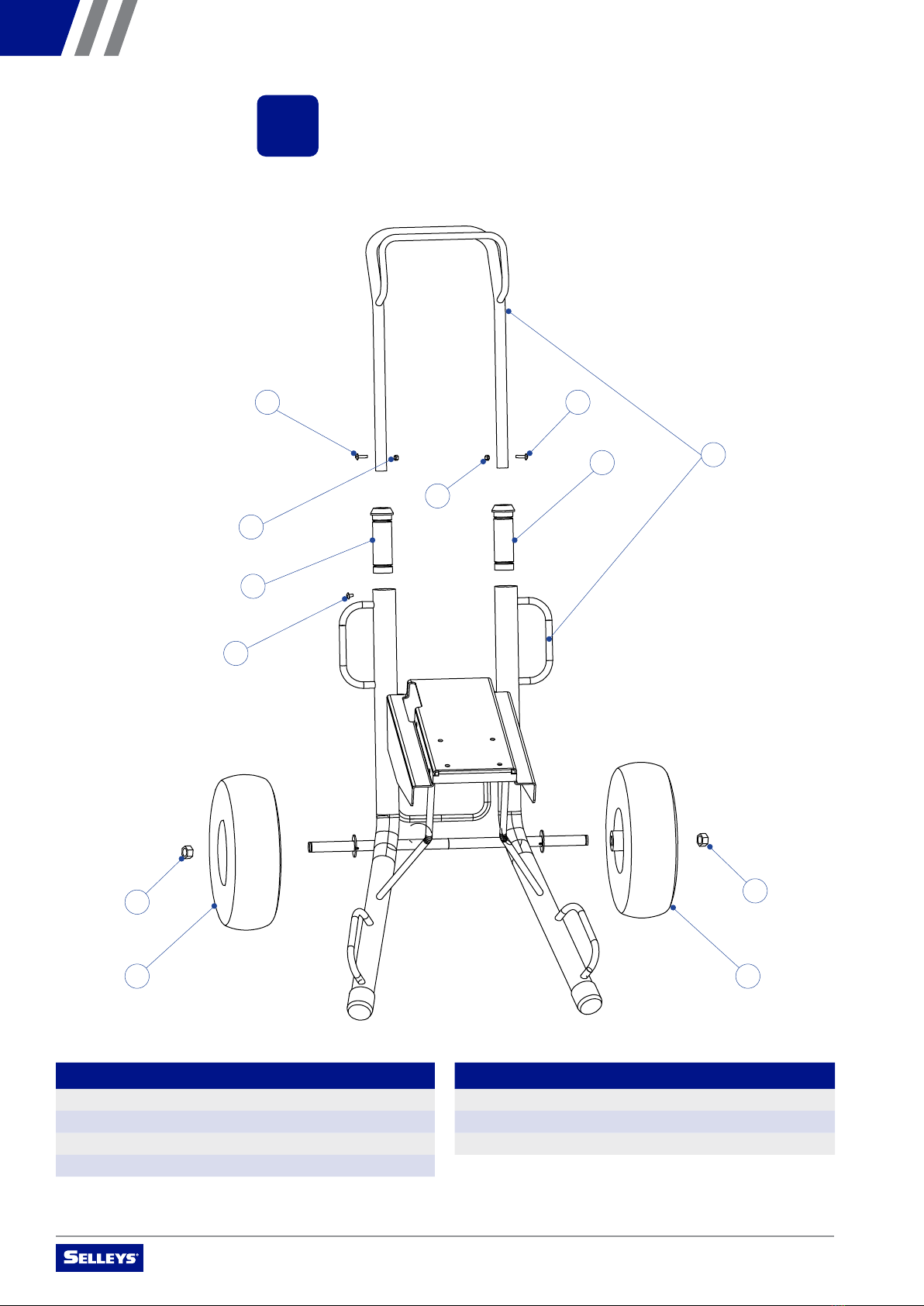
7. PARTS AND ASSEMBLY
Please read the following important information carefully.
NO. NAME QUANTITY
1001 Trolley frame 1
1002 Handle holder 2
1003 Hexagon nut M18 2
1004 Pneumatic tyre 2
NO. NAME QUANTITY
1005 Screw M4 * 25mm 2
1006 Hexagon nut M4 2
1007 Screw M5 * 5mm 1
OPERATING MANUAL – SELLEYS S39E
19
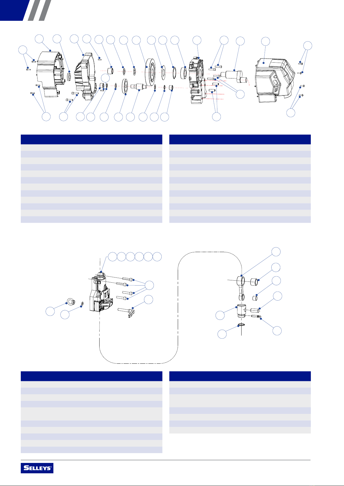
NO. NAME QUANTITY
101 Motor base 1
102 Roller bearing HF3520 1
103 Gear assembly 1
104 Ball bearing 6007 1
105 Circlip for hole ø62 1
105A Circlip for hole ø35 1
106 Electric motor 1
107 Hexagon screw M8 * 20mm 4
NO. NAME QUANTITY
108 Air shield 1
109 Hexagon screw 2
110 Axial fan 1
111 Screw ST4.8 * 16P * 15mm 4
112 Rear cover 1
113 Cross-head screw 2
114 Hexagon machine screw M8 * 20mm 4
113
112
110 109
109
108 106 105 104
105A 103 102 101
114 114
111
111
107
107
OPERATING MANUAL – SELLEYS S39E
20
NO. NAME QUANTITY
201 Middle cover 1
202 Ball bearing 1
203 Gearbox primary cover 1
204 Cylindrical pin 2
205 Ball bearing SCH1616 1
206 Ball bearing SCH1212 1
207 Gasket ø32 * ø19.05 * 1.6T 1
208 Gasket ø32 * ø19 * 0.8T 1
209 Secondary gear disc 1
210 Secondary gear shaft 1
211 Gear washer ø41 * ø25.7 * 3.2T 1
212 Gear washer ø39 * ø25.7 * 2.4T 1
NO. NAME QUANTITY
301 Piston sleeve (OD) ø57.2 *(ID) ø47 *76 (H) 1
302 Piston mount 1
303 Piston screw M10 1
304 Screw 4
305 Piston rotary shaft sleeve
(OD) ø12.7 * (ID) ø9.5
1
306 Piston rotary axis ø9.525 * 76mm 1
307 Piston hexagon screw BM10 * 80 8 60mm 1
308 Shank screw BM10 * 80 8 60mm 1
309 Double-sided washer M10 1
310 Nut M10 x SUS304 1
NO. NAME QUANTITY
401 Link rod 1
402 Needle roller bearing SCH1818 1
403 Self-lubricating bearing
(OD) ø23 * (ID) ø20 * 18.6mm
1
404 Piston valve ø47.6 * 67.5mm 1
405 Piston rod connecting pin ø20 * 38.1mm 1
406 Piston rod pin ø11.1 * 50mm 1
407 Spring wire (OD) ø1.5 * (ID) ø36.4 1
201 202 203 204 205 211 212 213 214 215 216 217 220
218
223 206 207 208 209 210 208 207 206
224
224
204
219
222
222
221
221
NO. NAME QUANTITY
213 Primary gear disc 1
214 Gasket ø84 * ø41.3 * 1.6T 1
215 Circlip for hole ø62 1
216 Roller bearing F-45087-00 1
217 Gearbox secondary cover 1
218 Eccentric gear 1
219 Cylindrical pin ø11.1 * 36mm 2
220 Front cover 1
221 Screw M5 * 10mm 4
222 Hexagon screw M8 * 35mm 4
223 Hexagon screw M8 * 50mm 2
224 Hexagon screw M8 * 1P * 30mm 4
308
310
309 404
407
406
405
403
402
401
301 302 303 305 306 307
304
Table of contents
Other Selleys Paint Sprayer manuals


Popular Paint Sprayer manuals by other brands


CAMPAGNOLA
CAMPAGNOLA LIPO 550 Use and maintenance manual

Campbell Hausfeld
Campbell Hausfeld PS240R Assembly instructions and parts list

Longray
Longray MistGen MG-SB16 user manual

Silvan Selecta
Silvan Selecta TR25-S7 instruction manual

Ryobi
Ryobi P2804 Operator's manual

Mesto
Mesto 3237 Instructions for use


