Selleys S21 AIRLESS SPRAYPACK User manual

SELLEYS S21 AIRLESS SPRAYPACK
SELLEYS S21 HI-BOY SPRAYPACK
OPERATING MANUAL

CONTENTS
1. SAFETY INFORMATION
1.1 General Safety Precautions
1.2 Specific Safety Hazards and Precautions
1.3 Earthing Instructions
2. COATINGS
2.1 Suitable Coatings
2.2 Preparation of Coating Materials
2.3 Viscosity
2.4 Coatings Containing Abrasive Materials
3. EQUIPMENT
3.1 Technical Data
3.2 Main Components
4. OPERATING INSTRUCTIONS
4.1 Starting Up
4.2 Control Panel Indicators
4.3 Connection to the Mains Network
4.4 Flushing of Preserving Agent
Before Starting Up
4.5 Before Spraying the Coating Material
4.6 Method of Spraying
1. SAFETY INFORMATION
Please read the following important information carefully.
The following symbols indicate specific types of safety hazards.
Indicates a potential hazard that may cause serious injury to the operator or
loss of life.
Indicates a potential hazard that may cause minor injury to the operator or
to the equipment.
Indicates important information.
4.7 Handling the High-Pressure Hose
4.8 In Case of Interrupted Operation
5. CLEANING AND MAINTENANCE
5.1 Cleaning and Shutting Down
5.2 Cleaning the Suction Filter
5.3 Cleaning the High-Pressure Filter
5.4 Cleaning the Airless Spray Gun
5.5 Disassembly of the Intake Filter
5.6 Assembly of the Intake Filter
6. MALFUNCTIONS
6.1 Corrective Measures for Common Malfunctions
6.2 Error Codes
7. SERVICING AND REPAIRS
7.1 Routine Checking
7.2 Repairs to the Relief Valve
7.3 Repairs to the Inlet and Outlet Valve
7.4 Repairs to the Packings
8. CONNECTION GUIDE
9. PARTS AND ASSEMBLY
WARNING
This unit is capable of extremely high spraying pressures that can cause serious and/or minor
injury by injection and extensive damage to property.
IMPORTANT
All replacement parts and accessories should ONLY be purchased from SELLEYS or an
authorised distributor of SELLEYS equipment. Servicing should ONLY be carried out by SELLEYS
or an authorised distributor of SELLEYS equipment. If these conditions are not met, the operator
assumes all liability for injury and property damage arising from the use of this unit.
OPERATING MANUAL – SELLEYS S21/S21 HI-BOY

OPERATING MANUAL – SELLEYS S21/S21 HI-BOY
3
1.1 GENERAL SAFETY PRECAUTIONS
NEVER
• use the spray gun without the safety guard in place
• operate faulty units or use faulty accessories
• attempt to repair a damaged hose
• leave this equipment unattended
• move the unit when it is running
• spray outside on windy days
ALWAYS
• ensure that this unit is properly earthed
• ensure that the power cord, air hose and spray hoses are optimally routed to minimise slip, trip and fall hazards
• immediately and thoroughly clean up all material and solvent spills to prevent slip hazards
• follow the material manufacturer’s instructions for safe handling of coating materials
• unplug the cord from the outlet before cleaning, maintaining or repairing this unit
• keep the power cord plug in sight during use to prevent accidental shutdowns and startups
• wear ear protection to protect against possible hearing loss from the noise produced by this unit, which can exceed 85 dB(A)
• keep this unit out of reach of children, unqualified adults and animals
• comply with local codes regarding ventilation, fire prevention, and operation
1.2 SPECIFIC SAFETY HAZARDS AND PRECAUTIONS
SAFETY HAZARD: INJECTION INJURY
WARNING
Serious risk of injection injury. This equipment produces a high-pressure stream that can pierce the skin and subcutaneous
tissues, resulting in severe injury and even possible amputation.
IMPORTANT
The maximum operating range of the unit is 220 bar (3200 PSI) fluid pressure.
NEVER
• put your fingers, hands or any other parts of your body into the spray jet
• point the spray gun at yourself or anyone else (including animals)
• allow the fluid stream to come into contact with any part of your body
• allow any leak in the fluid hose to come into contact with any part of your body
• put your hand in front of the gun
NOTE: Gloves do not provide full protection against injection injury.
ALWAYS
• ensure that the gun trigger is locked, the fluid pump is shut o, and all pressure is released before servicing, cleaning the
nozzle holder, changing spray tip, or leaving the unit unattended
NOTE: Turning o the engine will not release the pressure. The PRIME/SPRAY valve or pressure bleed valve must be turned to their appropriate
positions to relieve system pressure.
• ensure that the nozzle holder remains in place during spraying
• remove the spray tip before flushing or cleaning the system
• carefully check the paint hose for leaks before each use, as even small leaks can cause injection injury
• ensure that all accessories, including but not limited to spray tips, guns, extensions and hose, are rated at or above the
maximum operating pressure range of the sprayer
IMPORTANT MEDICAL INFORMATION
Injection injury is a traumatic injury that requires immediate medical attention. Any laceration of the skin, no matter how minor
it seems, should not be treated as a simple cut. Fully inform the medical team about the coatings or solvents involved, as some
coatings are toxic when injected directly into the bloodstream. For serious injuries, a plastic surgeon or reconstructive hand
surgeon should be consulted.

OPERATING MANUAL – SELLEYS S21/S21 HI-BOY
4
SAFETY PRECAUTIONS TO PREVENT EXPLOSIONS AND FIRE
WARNING
This equipment produces a high-pressure stream that can pierce the skin and subcutaneous tissues, resulting in severe injury
and even possible amputation.
NEVER
• use plastic drop cloths or enclose the spray area with plastic sheets, as plastic can cause static sparks
• smoke in the spray area
• use any materials with a flashpoint lower than 21 °C (70 °F)
NOTE: Flashpoint is the temperature at which a fluid can produce sucient vapours to ignite.
ALWAYS
• ensure that the spray area is well-ventilated to prevent the build-up of flammable vapours
• avoid all ignition sources such as static electricity sparks, electrical appliances, flames, pilot lights, hot objects, and sparks from
connecting and disconnecting power cords and/or working light switches
• flush the unit into a separate metal container, at the lowest possible pump pressure and with the spray tip removed
• hold the gun firmly against the side of the container to prevent static sparks
• have a fire extinguisher nearby
• place the sprayer at a minimum of 6.1 metres (20 feet) from the surface to be sprayed, extending the hose if necessary. Since
flammable vapours are often heavier than air, the floor area must be well ventilated. The pump contains arcing parts that emit
sparks, which can ignite vapours.
• ensure that the equipment and objects in and around the spray area are properly grounded to prevent static sparks
• ensure that you are using a conductive or earthed high pressure hose
• ensure that the gun is earthed through the hose connection
• ensure that the power cord is connected to a grounded circuit
• ensure that the unit is connected to an earthed object such as a water pipe, steel beam, or other electrically earthed surface, via
the green earthing wire
• strictly follow the material and solvent manufacturer’s warnings and instructions, and read the coating material’s MSDS
(Material Safety Data Sheet) and technical information before use
SAFETY PRECAUTIONS TO PREVENT EXPLOSIONS DUE TO INCOMPATIBLE MATERIALS
WARNING
Serious risk of explosions due to incompatible materials. Accidental explosions due to incompatible materials can cause serious
injury and/or extensive damage to property.
NEVER
• use materials that contain bleach or chlorine
• use halogenated hydrocarbon solvents such as methylene chloride and 1,1,1-trichloroethane
NOTE: These substances are not compatible with aluminium and may cause an explosion. If you are in any doubt over a material’s compatibility
with aluminium, check with your coating supplier.
SAFETY PRECAUTIONS TO PREVENT HARM FROM TOXIC VAPOURS
WARNING
Vapours from paints, solvents, insecticides, and other materials can be harmful in the event of inhalation or contact with any part
of the body. Symptoms include severe nausea, fainting and poisoning.
ALWAYS
• use a respirator or mask
• wear protective eyewear
• wear protective clothing

OPERATING MANUAL – SELLEYS S21/S21 HI-BOY
5
1.3 EARTHING INSTRUCTIONS
NEVER
• operate this unit unless you are sure that it has been properly earthed
• modify the earthing plug
ALWAYS
• ensure that the earthing plug is plugged into an outlet that has been properly installed and earthed in accordance with local
codes
• seek the advice of a qualified electrician if you need a new outlet installed to fit the earthing plug, do not fully understand these
earthing instructions, or are unsure as to whether this unit is properly earthed
WARNING
Incorrect installation of the earthing plug can result in electric shock. If you need to repair or replace the cord or plug, do not
connect the green earthing wire to either blade terminal.
IMPORTANT
The wire with insulation, which has a green outer surface with or without yellow stripes, is the earthing wire. It must be
connected to the earthing pin.
A list of the materials used in the construction of this unit is available upon request for the purpose of determining compatibility
with coating materials.
2. COATINGS
Read the following important information carefully.
2.1 SUITABLE COATINGS
This unit is suitable for the application of:
• dilutable lacquers and paints
• coatings containing solvents
• dispersions
• latex paints
Do not spray coatings other than those listed above without the prior approval of SELLEYS or the authorised distributor of this unit.
Always filter and stir the coating material before application. To prevent downtime, make sure that no air bubbles are introduced,
especially when stirring the coating material with motor-driven agitators.
2.2 PREPARATION OF COATING MATERIALS

OPERATING MANUAL – SELLEYS S21/S21 HI-BOY
6
This unit is able to process highly viscous coating materials of up to around 20,000 mPa-s.
Highly viscous coating materials can be diluted according to the manufacturer’s instructions.
Coatings that contain sharp-edged aggregates and additional materials cause intense wear and tear on this unit’s parts, including
its valves, high-pressure hose, spray gun and spray tip.
Use of abrasive coatings may shorten the working life of this unit.
2.4 COATINGS CONTAINING ABRASIVE MATERIALS
3. EQUIPMENT
3.1 TECHNICAL DATA
Voltage 220 V / 50 Hz
Motor output 1.1 kW
Max. operating pressure 220 bar
Flow rate 2.3 L/min
Max. nozzle size 0.021”
Max. temperature of the coating material 43 ºC
Max. viscosity 20,000 mPa-s
Weight 17 kg
High pressure hose DN 6 mm, 15 m
Dimensions (L x W x H) 440 x 370 x 420 mm
Max. sound pressure level 80 dB
2.3 VISCOSITY
Please read the following important information carefully.

OPERATING MANUAL – SELLEYS S21/S21 HI-BOY
7
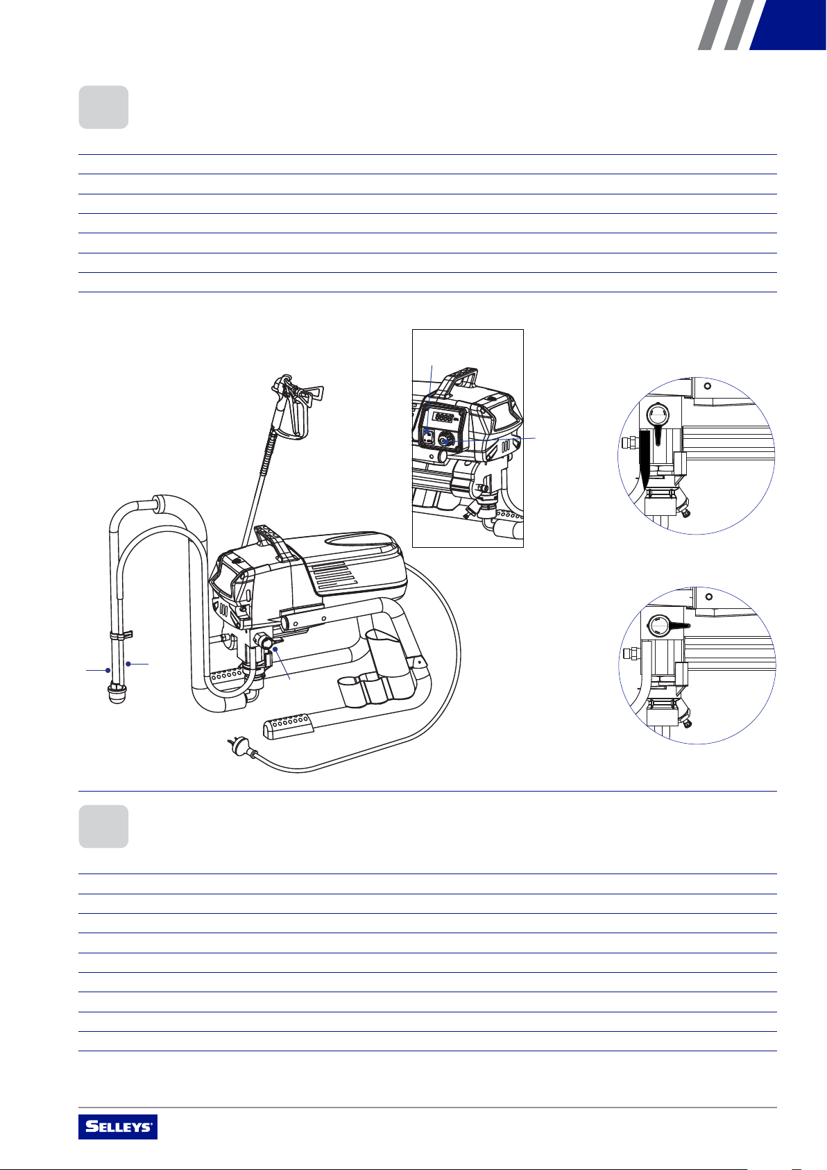
3.2 MAIN COMPONENTS
912
11
10
1
2
4
3
5
6
7
8
14
Figure 1
912
11
10
1
2
4
3
5
6
7
8
14
NO. NAME
1 Spray gun
2 High-pressure hose
3 Suction hose
4 Return hose
5Frame
6 Drip cup
7 Power cord
NO. NAME
8 Relief valve
9 ON/OFF switch
10 Pressure control knob
11 Pressure stem
12 Manometer indicator
13 Oil reservoir
14 Suction filter

OPERATING MANUAL – SELLEYS S21/S21 HI-BOY
8
4.1 STARTING UP
Follow these steps carefully.
1. Screw the high-pressure hose to the coating material outlet
2. Screw the spray gun with the selected spray tip onto the high-pressure hose
3. Tighten the union nuts at the high-pressure hoses to prevent coating from leaking
4. Drip a few drops of the lubricating oil into the oil reservoir
5. Fully depress the pressure stem to ensure that the inlet ball is free
4. OPERATING INSTRUCTIONS
Please read the following important information carefully.
The following diagrams depict the control panel indicators. Set the pressure control knob to the required pressure to start work.
Turn clockwise to increase pressure, and counter-clockwise to decrease pressure.
4.2 CONTROL PANEL INDICATORS
4.3 CONNECTION TO THE MAINS NETWORK
Figure 2: Pulsating pressure
for cleaning zone
Figure 3: The minimum pressure
is increasing clockwise
Electrical System: 220 VAC / 50 Hz
The unit must be connected to a securely grounded safety outlet.
Before connecting the unit to the mains supply, ensure that the line voltage complies with the specification on the unit’s
rating plate.
Oil
reservoir
OPERATING MANUAL – SELLEYS S21/S21 HI-BOY
9
912
11
10
1
2
4
3
5
6
7
8
14
Follow these steps carefully.
1. Immerse the suction hose (Figure 4.1) and return hose (4.2) in a container with a suitable cleaning agent
2. Turn the pressure control knob (4.5) counter-clockwise to minimum pressure
3. Open the relief valve (4.3) and set it to PRIME (Figure 5)
4. Switch the unit ON (4.4)
5. Wait until the cleaning agent discharges from the return hose
6. Turn the relief valve (4.3) and set it to SPRAY (Figure 6)
7. Pull the trigger of the spray gun
8. Spray the cleaning agent from the unit into an open container
4.4 FLUSHING OF PRESERVING AGENT BEFORE STARTING UP
4.5 BEFORE SPRAYING THE COATING MATERIAL
Follow these steps carefully.
1. Immerse the suction hose (Figure 4.1) and return hose (4.2) in the coating material container
2. Turn the pressure control knob (4.5) counter-clockwise to minimum pressure
3. Open the relief valve (4.3) and set it to PRIME (Figure 5)
4. Switch the unit ON (4.4)
5. Wait until the coating material discharges from the return hose
6. Turn the relief valve (4.3) and set it to SPRAY (Figure 6)
7. Trigger the spray gun several times and spray into a container until the coating material exits the spray gun
8. Increase the pressure by slowly turning the pressure control knob (4.5) clockwise
9. Check the spray pattern and increase the pressure until the desired atomisation is attained
10. The unit is ready to spray
Figure 4
Figure 5
Figure 6
912
11
10
1
2
4
3
5
6
7
8
14
1
3
2
4
5
OPERATING MANUAL – SELLEYS S21/S21 HI-BOY
10
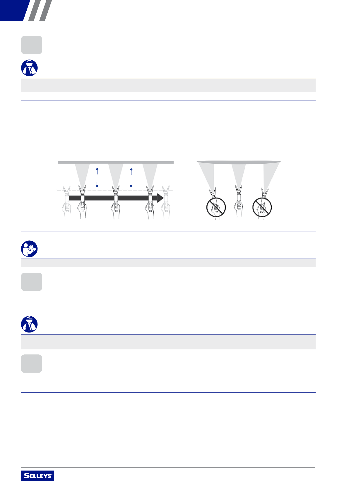
4.6 METHOD OF SPRAYING
WARNING
Never trigger the gun unless the spray tip is completely turned to either the spray or the unclog position. Always engage the gun
trigger lock before removing, replacing or cleaning the spray tip.
Follow these steps carefully.
1. Ensure that the nozzle holder is in place
2. Trigger the gun AFTER starting the stroke
3. To ensure even application:
• keep your arm moving at a constant speed
• keep the spray gun perpendicular to the surface
• keep the spray gun at a constant distance of 25 to 30 cm from the surface
• overlap each stroke by about 30%
4. Release the gun BEFORE ending the stroke
IMPORTANT
If very sharp edges or streaks appear on the coated surface, increase the operating pressure or dilute the coating material.
Avoid sharp bending or kinking of the high-pressure hose. The smallest bending radius amounts to about 20 cm.
Do not drive over the high-pressure hose, and avoid contact with sharp objects and edges.
WARNING
Defective high-pressure hoses can leak and cause serious injection injury. Replace defective high-pressure hoses immediately.
Never attempt to repair a defective high-pressure hose.
4.7 HANDLING THE HIGH-PRESSURE HOSE
4.8 IN CASE OF INTERRUPTED OPERATION
Follow these steps carefully.
1. Open the relief valve (Figure 4.3) and set it to PRIME (Figure 5)
2. Switch the unit OFF (4.4)
3. Turn the pressure control knob (4.5) counter-clockwise to minimum pressure
25 – 30 cm 25 – 30 cm
25 – 30 cm 25 – 30 cm
OPERATING MANUAL – SELLEYS S21/S21 HI-BOY
11
5.1 CLEANING AND SHUTTING DOWN
CLEANING THIS UNIT
1. Clean and remove the spray tip
NOTE: If using a non-standard spray tip, refer to the relevant Operating Manual for cleaning instructions.
2. Remove the suction hose (Figure 4.1) from the coating material
3. Close the relief valve (4.3) and set it to SPRAY (Figure 6)
4. Switch the unit ON (4.4)
5. Pull the trigger of the spray gun and pump the remaining coating material from the suction hose, high-pressure hose and
spray gun into an open container
WARNING
The container must be earthed in case of coating materials that contain solvents. Do not pump or spray unused coating material
into a container with a small opening (bunghole).
6. Immerse the suction hose with return hose in a container with a sucient amount of a suitable cleaning agent
NOTE: Cleaning agent’s ignition point must exceed 21 ºC.
7. Turn the pressure control knob (4.5) into the blue zone-pulsating pressure for unit cleaning (Figure 2)
8. Open the relief valve (4.3) and set it to PRIME (Figure 5)
9. Pump a suitable cleaning agent in the circuit for a few minutes
10. Pour any remaining cleaning agent into an open container until the unit is empty
11. Switch the unit OFF (4.4)
5. CLEANING AND MAINTENANCE
Please read the following important information carefully.
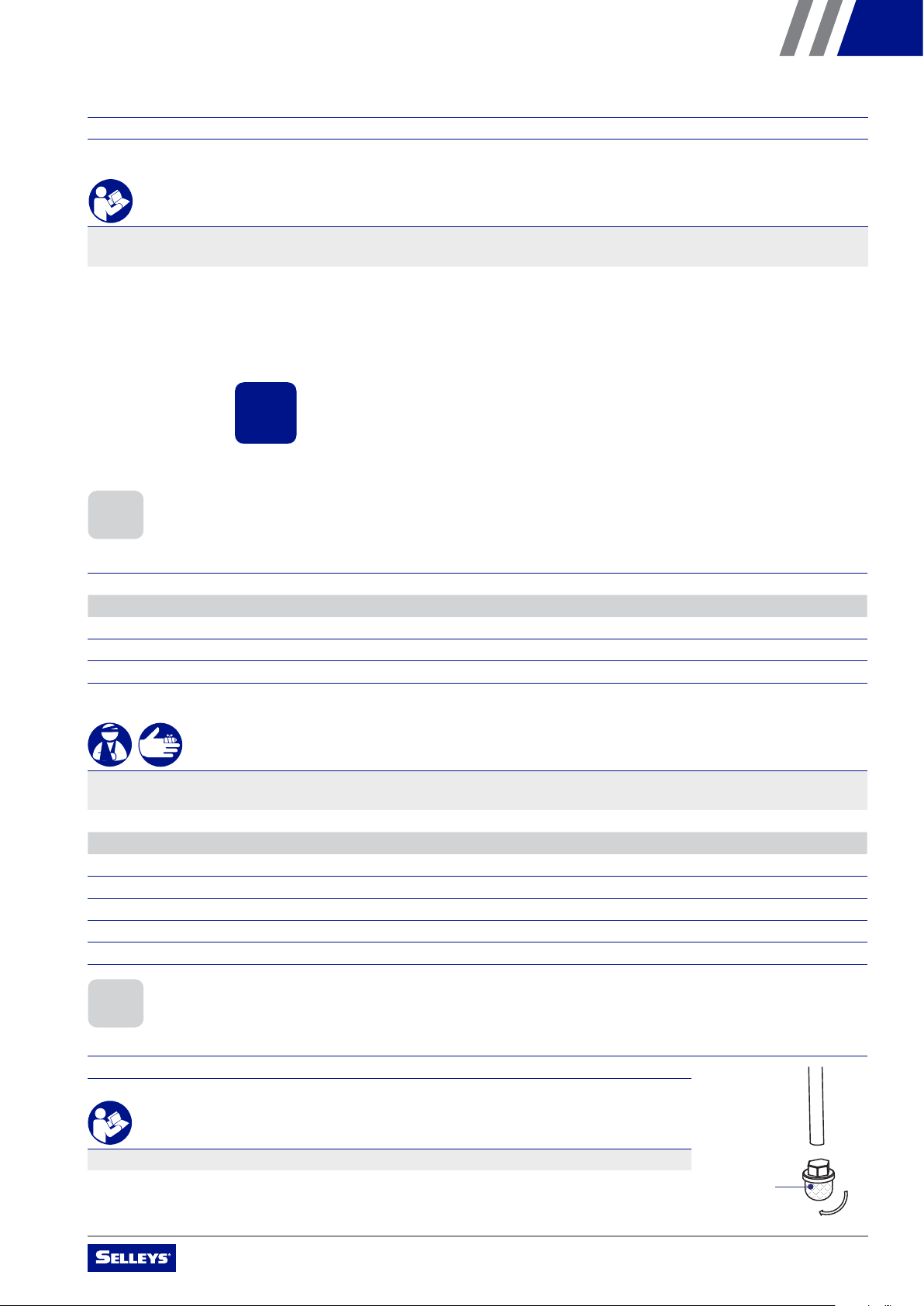
5.2 CLEANING THE SUCTION FILTER
Follow these steps carefully to ensure optimal feed, constant spraying pressure and smooth operation.
1. Unscrew the suction filter (Figure 7.1) from the suction hose
4. Pull the trigger of the spray gun in order to release the pressure from the high-pressure hose and spray gun
5. Secure the spray gun
6. Leave the suction tube (or the suction hose and return hose) immersed in the coating material, or swivel or immerse it in a
suitable cleaning agent
IMPORTANT
If a fast-drying or two-component coating material is used, ensure that the unit is rinsed with a suitable cleaning agent within the
processing time.
2. Clean the suction filter with a hard brush and a sucient amount of a suitable cleaning agent
IMPORTANT
Replace the suction filter if it is clogged or faulty.
1
Figure 7

OPERATING MANUAL – SELLEYS S21/S21 HI-BOY
12
5.4 CLEANING THE AIRLESS SPRAY GUN
Follow these steps carefully.
1. Rinse the airless spray gun with a sucient amount of a suitable cleaning agent
2. Thoroughly clean the spray tip with a sucient amount of a suitable cleaning agent until all
unused coating material has been removed
3. Thoroughly clean the outside of the airless spray gun
Follow these steps carefully.
1. Pull the protective guard (Figure 9.1) forward with moderate force
2. Unscrew the grip (9.2) from the gun housing and remove the intake filter (9.3)
IMPORTANT
Replace the intake filter if it is clogged or faulty.
5.6 ASSEMBLY OF THE INTAKE FILTER
Follow these steps carefully.
1. Place the intake filter (Figure 9.3) with the long cone into the gun housing
2. Screw the grip (9.2) into the gun housing and tighten
3. Slot in the protective guard (9.1)
1
3
2
Figure 9
1
4
3
5
2
Figure 8
5.3 CLEANING THE HIGH-PRESSURE FILTER
Follow these steps carefully.
1. Turn the pressure control knob (Figure 4.5) counter-clockwise to minimum pressure
2. Open the relief valve (4.3) and set it to PRIME (Figure 5)
3. Switch the unit OFF (4.4)
WARNING
Always unplug the power plug from the outlet.
4. Unscrew the filter housing (Figure 8.1) with a strap wrench
5. Pull the filter cartridge (8.2) from the bearing spring (8.3)
6. Clean all parts with a sucient amount of a suitable cleaning agent
7. Check the O-ring (8.4) and replace it if necessary
8. Place the bearing ring (8.5) against the bearing spring (8.3). Slide the filter cartridge (8.2) over
the bearing spring.
9. Open the relief valve (4.3) and set it to PRIME (Figure 5)
IMPORTANT
The container must be earthed in case of coating materials that contain solvents.
5.5 DISASSEMBLY OF THE INTAKE FILTER
6. MALFUNCTIONS

OPERATING MANUAL – SELLEYS S21/S21 HI-BOY
13
6. MALFUNCTIONS
Refer to the chart below for instructions on how to correct common malfunctions.
6.1 CORRECTIVE MEASURES FOR COMMON MALFUNCTIONS
TYPE OF MALFUNCTION POSSIBLE CAUSES CORRECTIVE MEASURES
A. Unit does not start 1. No voltage applied
2. Pressure setting is too low
3. ON/OFF switch is defective
1. Check voltage supply
2. Turn up pressure control knob
3. Replace
B. Unit does not draw in material 1. Relief valve is set to SPRAY
2. Filter projects over the fluid level
and sucks air
3. Filter is clogged
4. Suction hose/suction tube is loose, i.e.
the unit is sucking in outside air
1. Set relief valve to PRIME (circulation)
2. Refill the coating material
3. Clean or replace the filter
4. Clean connecting points. Replace
O-rings if necessary. Secure suction
hose with retaining clip.
C. Unit draws in material, but the
pressure does not build up
1. Spray tip is heavily worn
2. Spray tip is too large
3. Pressure setting is too low
4. Filter is clogged
5. Coating material flows through the
return hose when the relief valve is
in the SPRAY position
6. Packings are sticky or worn
7. Valve balls are worn
8. Valve seats are worn
1. Replace
2. Select a smaller spray tip
3. Turn pressure control knob clockwise
to increase pressure
4. Clean or replace the filter
5. Remove and clean or replace
relief valve
6. Remove and clean or replace packings
7. Remove and replace valve balls
8. Remove and replace valve seats
D. Coating material exits at the top
of the fluid section
1. Upper packing is worn
2. Piston is worn
3. Incorrect high-pressure
hose type
1. Remove and replace packing
2. Remove and replace piston
3. Only use original
high-pressure hoses
E. Increased pulsation at the
spray gun
1. Incorrect high-pressure hose type
2. Spray tip is worn or too large
3. Pressure is too high
1. Only use original-high pressure hoses
2. Replace spray tip
3. Turn pressure control knob to a lower
number
F. Poor spray pattern 1. Spray tip is too large for the coating
material being sprayed
2. Pressure setting is incorrect
3. Volume is too low
4. Coating material viscosity
is too high
1. Replace spray tip
2. Turn pressure control knob until a
satisfactory spraying pattern is achieved
3. Clean or replace all filters
4. Thin out according to the manufacturer’s
instructions
G. Unit loses power 1. Pressure setting is too low 1. Turn pressure control knob clockwise to
increase

OPERATING MANUAL – SELLEYS S21/S21 HI-BOY
14
6.2 ERROR CODES
ERROR CODE ERROR DESCRIPTION CONDITIONS MAINTENANCE ADVICE
ERR_1 Hardware overcurrent
protection
Hardware overcurrent circuit
signal is detected
1. Switch power OFF and ON
2. Replace circuit board
3. Replace electric motor
ERR_2 Software detects that the motor
current is high
The software detects the
motor current is high
1. Switch power OFF and ON
2. Replace circuit board
3. Replace electric motor
ERR_3 Bus-bar voltage is high The input voltage is high 1. Check that input voltage is
not more than 260 VAC
2. Replace circuit board
ERR_4 Bus-bar voltage is low The input voltage is low 1. This feature is temporarily
disabled
ERR_5 Abnormal motor hall The three halls of the motor
appear at high level or low level
1. Check that the hall terminal
is tightly fitted into the
circuit board
2. Replace circuit board
3. Replace electric motor
ERR_9 Chip memory error alarm An error occurred while data
is stored in the chip
1. Replace circuit board
ERR_10 Motor current amplifier error The internal operational
amplifier circuit is abnormal when
the motor is not running
1. Replace circuit board
ERR_11 High pressure error The output circuit voltage of
the pressure sensor is high
1. Reduce pressure
ERR_12 The motor is protected when
the equipment has no pressure
A protection mechanism when the
motor is running continuously for
one minute during return phase
1. Switch power OFF and ON
ERR_13 Chip ID error Abnormality was detected
after powering ON
1. Replace circuit board
ERR_14 Starter motor stall protection The motor is blocked or
not running
1. Check that the UVW
connection of the motor
is intact
2. Replace circuit board
3. Replace electric motor
ERR_15 Pressure sensor failure Detected abnormal signal
of pressure sensor
1. Check that the pressure
sensor is well connected
2. Replace pressure sensor
3. Replace circuit board
ERR_16 Communication check
code error
The chip indicated a checksum
error during internal communication
1. Replace circuit board
ERR_17 Abnormal pressure feedback The pressure estimated by
the software diers from the
actual pressure
1. Check that the pressure
sensor is well connected
2. Replace pressure sensor
3. Replace circuit board
ERR_18 Communication failure No communication signal
is received in the chip
1. Replace circuit board

OPERATING MANUAL – SELLEYS S21/S21 HI-BOY
15
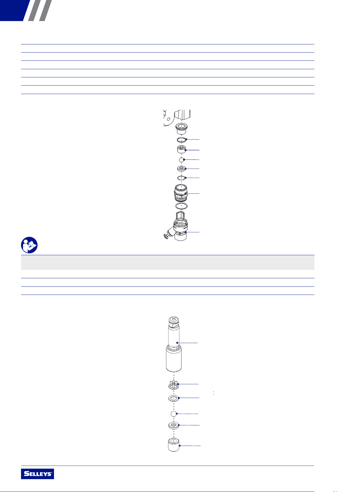
7.3 REPAIRS TO THE INLET AND OUTLET VALVE
Follow these steps carefully.
1. Remove the four screws in the front cover and remove the front cover
2. Switch the unit ON and then OFF so that the piston rod is positioned in the lower stroke position
WARNING
To avoid crushing injury, never reach into moving parts with fingers or tools.
7. SERVICING AND REPAIRS
Please read the following important information carefully.
7.1 ROUTINE CHECKING
Prior to every use/on a weekly basis:
• check the high-pressure hoses and the device connecting the line and plug for damage and wear
• check the inlet valve, outlet valve and filter for damage and wear
• check the high-pressure hose for any notches or bulges, especially around the transitions in the fittings. You should
be able to easily turn the union nuts, without using force.
7.2 REPAIRS TO THE RELIEF VALVE
Follow these steps carefully.
1. Use a drift punch of 2 mm to remove the grooved pin (Figure 10.1) from the relief valve (10.2)
2. Remove the relief valve (10.2) and cam base (10.3)
3. Remove the valve housing (10.4) from the pump assembly (10.6) with a wrench
4. Ensure that the seal (10.5) is seated correctly, then screw the new valve housing (10.4) completely into the pump assembly (10.6)
and tighten with a wrench
5. Align the cam base (10.3) with the hole in the pump assembly (10.6). Lubricate the cam base with grease and slide on the cam base.
6. Align the hole in the valve shaft (10.7) with the hole in the relief valve (10.2)
1
2
3
7
5
4
6
Figure 10
Repairs to the Relief Valve (Section 7.2), Inlet and Outlet Valve (Section 7.3), and Packings (Section 7.4) should only be carried out by
a qualified electrician or an authorised distributor of SELLEYS equipment.
Remember to get this unit serviced annually (or more often in the case of heavy usage) by an authorised distributor of SELLEYS
equipment.
WARNING
Always unplug the power plug from the outlet before commencing any repair works on the unit.
OPERATING MANUAL – SELLEYS S21/S21 HI-BOY
16
3. Unplug the power plug from the outlet
4. Remove the retaining clip from the connecting bend at the suction hose and pull o the suction hose
5. Unscrew the return hose
6. Swivel the unit 90° to the rear in order to comfortably access the material feed pump
7. Remove the pressure stem clip and slide the pressure stem housing (Figure 11.7) from the inlet valve housing (11.1)
8. Unscrew the inlet valve housing (11.1) from the pump manifold
9. Remove the lower seal (11.2), lower ball guide (11.3), inlet valve ball (11.4), inlet valve seat (11.5) and O-ring (11.6)
10. Clean all the parts with an appropriate cleaning agent
IMPORTANT
Check the inlet valve housing (Figure 11.1), inlet valve seat (11.5) and inlet valve ball (11.4) for wear and replace them if necessary. If the
worn inlet valve seat (11.5) is unused on one side, remove it and reinstall it the other way round.
11. Unscrew outlet valve housing (Figure 12.8) from the piston (12.9) with adjusting wrench
12. Check the inlet valve housing (Figure 11.1), inlet valve seat (11.5) and inlet valve ball (11.4) for wear and replace the parts if necessary
13. Remove the upper ball cage (Figure 12.11), washer (12.10), outlet valve ball (12.12), and outlet valve seat (12.13)
14. Install parts in the reverse order, lubricating the O-ring (Figure 11.6) with grease and ensuring proper seating in the inlet valve
housing (11.1)
9
11
10
10
12
13
8
Figure 12
2
33
5
6
1
7
4
Figure 11

OPERATING MANUAL – SELLEYS S21/S21 HI-BOY
17
7.4 REPAIRS TO PACKINGS
Follow these steps carefully.
1. Remove the inlet valve housing according to the instructions outlined in Section 7.3 of this Operating Manual
2. Unscrew both cylinder head screws (Figure 13.1) from the pump assembly (13.2) with a 3/8-inch hexagon socket head wrench
3. Slide the pump assembly (13.2) and piston (13.3) forward until the piston is out of the T-slot (13.9) on the slider assembly (13.4)
4. Push the piston (13.3) downward out of the pump assembly (13.2)
5. Unscrew the retainer nut (13.5) from the pump assembly (13.2) and remove the piston guide (13.6)
6. Remove the upper packing (13.7) and lower packing (13.8) from the pump
7. Clean the pump assembly (13.2)
8. Lubricate the upper packing (13.7) and lower packing (13.8) with grease
9. Insert the upper packing with O-ring (Figure 14.1) and protruding lip (14.2) downward
10. Insert the lower packing with the bevelled edge (Figure 15.1) facing upward
11. Insert the piston guide (Figure 13.6) into the retainer nut (13.5)
12. Screw the retainer nut (13.5) into the pump assembly (13.2) and tighten by hand
13. Push the installation tool (included with the replacement packings) for the piston (13.3) from above onto the piston
14. Lubricate the installation tool and piston (13.3) with grease
1
3
2
7
4
9
6
8
5
Figure 13
Figure 14
2
1
Figure 15
1

OPERATING MANUAL – SELLEYS S21/S21 HI-BOY
18
15. Guide the piston (13.3) through the lower packings (13.8) into the pump assembly (13.2) from below
16. Using a rubber mallet, lightly tap the piston (13.3) from below until it can be seen above the pump assembly
17. Remove the installation tool from the piston (13.3)
18. Carefully tighten the retainer nut (13.5) with an adjusting wrench
19. Slide the top of the piston (13.3) into the T-slot (13.9) on the slider assembly (13.4)
20. Position the pump assembly (13.2) underneath the gear unit housing and push up until it rests against the gear unit housing
21. Screw the pump assembly (13.2) to the gear unit housing
22. Lubricate the O-ring (Figure 11.6) between the pump assembly (11.2) and the inlet valve housing with machine grease the
pump manifold
23. Screw the inlet valve housing to the pump assembly
24. Insert the elbow on the siphon assembly into the button of the pusher stem housing
25. Push the retaining clip up into the groove inside the foot valve housing to secure the siphon assembly in position
26. Place the return tube over the return tube fitting and secure with the clip the gear unit housing
27. Install the front cover
8. CONNECTION GUIDE
Switch
Brown
White
Blank
Red
N
L
Fuse
Motor controller
Pressure sensor
Hall sensor
Potentiometer
Motor
N
LN
L
Blank
Blank
White
Display board
Red
Blank
Brown
Orange
Yellow
Ground
220V 50Hz
9. PARTS AND ASSEMBLY
Please examine the following diagrams carefully.
OPERATING MANUAL – SELLEYS S21/S21 HI-BOY
19
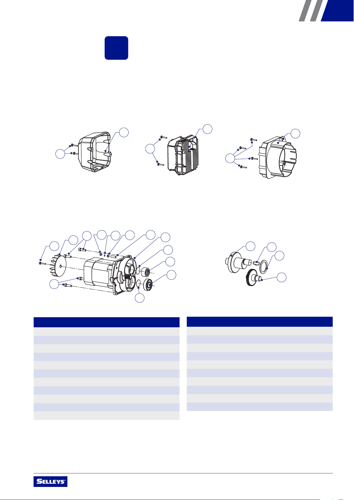
9. PARTS AND ASSEMBLY
Please examine the following diagrams carefully.
102
101
201
302
401
402
411 410 409 408 404
405
406
407
501 504
502
503
603
604
607
605
606
701
704
701 702
602
202
301
403
403
601
703
705
405
Cover Sets Driver Sets Bae
NO. NAME QUANTITY
101 Screw 2
102 Electric motor cover 1
201 Electric control assembly 1
202 Screw 2
301 Screw 4
302 Bae 1
401 Screw 1
402 Fan 1
403 Screw 4
404 Motor 1
405 Shim ring 2
NO. NAME QUANTITY
406 Needle bearing 1
407 Ball bearing 1
408 Screw 1
409 Nut 1
410 Nut 1
411 Nut 1
501 Primary crankshaft 1
502 Seat 1
503 Secondary crankshaft 1
504 Glib 1
102
101
201
302
401
402
411 410 409 408 404
405
406
407
501 504
502
503
603
604
607
605
606
701
704
701 702
602
202
301
403
403
601
703
705
405
Motor Gear
102
101
201
302
401
402
411 410 409 408 404
405
406
407
501 504
502
503
603
604
607
605
606
701
704
701 702
602
202
301
403
403
601
703
705
405
OPERATING MANUAL – SELLEYS S21/S21 HI-BOY
20
102
101
201
302
401
402
411 410 409 408 404
405
406
407
501 504
502
503
603
604
607
605
606
701
704
701 702
602
202
301
403
403
601
703
705
405
Housing Belly Pan
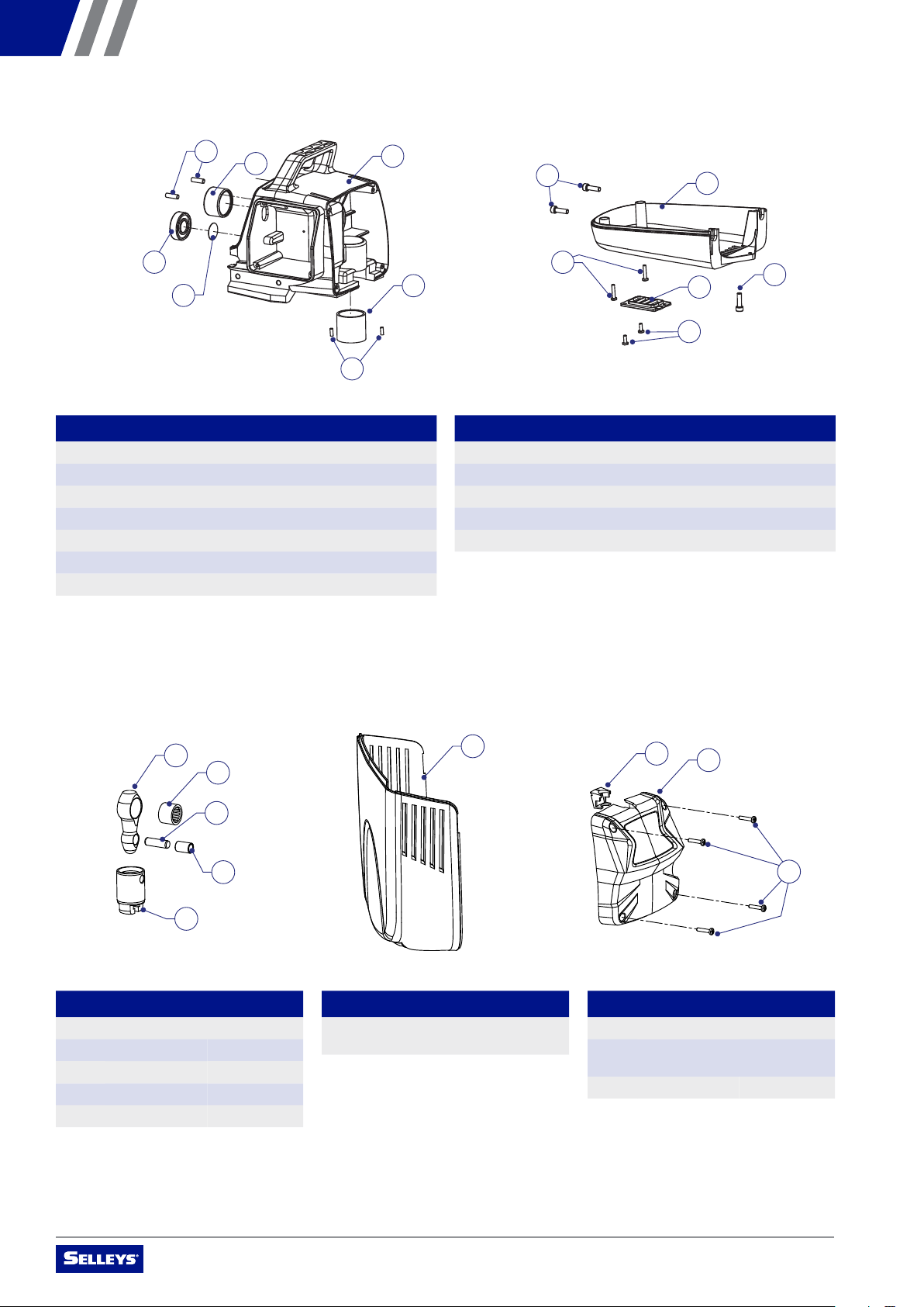
NO. NAME QUANTITY
601 Pin 2
602 Ball bearing 1
603 Needle bearing 1
604 Shim ring 1
605 Housing cover 1
606 Bushing cap 1
607 Pin 2
NO. NAME QUANTITY
801 Slider 1
802 Needle bearing 1
803 Pin 1
804 Bushing cap 1
805 T-slot 1
NO. NAME QUANTITY
1001 Cap 1
1002 Electric motor
face plate
1
1003 Screw 4
NO. NAME QUANTITY
901 Electric motor
shroud
1
NO. NAME QUANTITY
701 Screw 3
702 Belly pan cover 1
703 Screw 2
704 Belly pan bottom cover 1
705 Screw 2
102
101
201
302
401
402
411 410 409 408 404
405
406
407
501 504
502
503
603
604
607
605
606
701
704
701 702
602
202
301
403
403
601
703
705
405
Slider Set Face Plate SetMotor Shroud Set
801
802
803
804
805
901
1001 1002
1106
1101
1103
1102
1105
1107
1108
1201
1202
1203
1204
1205
1206
1207
1208
1209
1303
1301
1305
1306
1307
1302
1308
1304
1302
1003
1210
1104
801
802
803
804
805
901
1001 1002
1106
1101
1103
1102
1105
1107
1108
1201
1202
1203
1204
1205
1206
1207
1208
1209
1303
1301
1305
1306
1307
1302
1308
1304
1302
1003
1210
1104
801
802
803
804
805
901
1001 1002
1106
1101
1103
1102
1105
1107
1108
1201
1202
1203
1204
1205
1206
1207
1208
1209
1303
1301
1305
1306
1307
1302
1308
1304
1302
1003
1210
1104
This manual suits for next models
1
Table of contents
Other Selleys Paint Sprayer manuals


Popular Paint Sprayer manuals by other brands

Scientific Industries
Scientific Industries ROTO-SHAKE GENIE operating instructions

Titan
Titan Speeflo Hydra M 2000 owner's manual

Bosch
Bosch PFS 1000 Original instructions

Parkside
Parkside PDFP 500 A1 Operation and safety notes

Raider
Raider PRO RDP-SBKMD20 SOLO user manual

Ribimex
Ribimex RBAT20 PRBAT20/PPSB instructions

WAGNER
WAGNER WallPerfect W 995 Original operating instructions

PBM
PBM HAV Series Owner's/operator's manual

RED DEVIL
RED DEVIL 5400-02 owner's manual

Milwaukee
Milwaukee HEAVY DUTY M12 BHCS3L user manual

DS Produkte
DS Produkte Q0P-WYT16-18 Translation of the original operating instructions

OneTech
OneTech NT10-400R-04 Manual instruction


