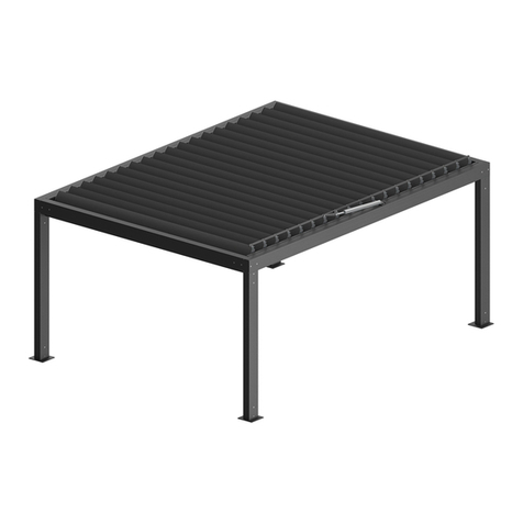
SELT Pergola SB400 User manual

TECHNICAL AND OPERATIONAL DOCUMENTATION
INSTALLATION MANUAL
OPERATING MANUAL AND INSTRUCTIONS FOR SAFE USE
5. Steel and aluminium components and structural sets
5.8. Pergola SB400 (2020)
5.8
DT-E

DT-E 5.8: ALUMINIUM CONSTRUCTION –PERGOLA SYSTEM SB400 (2020)
Edition 2 / June 2020 / EN strona 2 / 42
PRODUCT NAME:
ALUMINIUM CONSTRUCTION
PERGOLA SB400 (2020)
MARKING OF PRODUCT MANUFACTURER:
Manufacturer name:
SELT Sp. z o. o.
Manufacturer’s registered office:
45- 449 Opole, ul. Wschodnia 23A
Contact details:
Tel: +48 77 553 21 00 (secretariat)
Fax: +48 77 553 22 00
Website:
www.selt.com
Email:
PRODUCT SAFETY MARKING:
The product meets the CE safety requirements.
THIS TECHNICAL AND OPERATIONAL DOCUMENTATION:
is valid from: 01 June 2020
is applicable to the above-listed product versions.

DT-E 5.8: ALUMINIUM CONSTRUCTION –PERGOLA SYSTEM SB400 (2020)
Edition 2 / June 2020 / EN strona 3 / 42
TABLE OF CONTENTS
1INTRODUCTION............................................................................................................................................................ 4
1.1 SAFETY GUIDELINES FOR THE PRODUCT................................................................................................................. 4
1.2 EXPLANATION OF SYMBOLS AND SIGNS ................................................................................................................. 4
1.3 TERMS AND DEFINITIONS ....................................................................................................................................... 5
1.4 SUBJECT, INTENDED USE AND CONTENTS OF THE DOCUMENTATION................................................................... 5
2PRODUCT TECHNICAL INFORMATION.......................................................................................................................... 7
2.1 TECHNICAL PARAMETERS: ...................................................................................................................................... 7
2.2 PRODUCT SPECIFICATION ....................................................................................................................................... 9
3TRANSPORT AND STORAGE OF THE PRODUCT .......................................................................................................... 10
3.1 COMPLETENESS AND QUALITY CONDITION OF DELIVERY .................................................................................... 10
3.2 GENERAL CONDITIONS FOR TRANSPORT AND STORAGE OF THE PRODUCT ........................................................ 10
3.3 OBLIGATORY DESCRIPTIONS TO BE PLACED ON THE PRODUCT PACKAGING ....................................................... 10
4PRODUCT INSTALLATION........................................................................................................................................... 11
4.1 GENERAL REQUIREMENTS FOR SAFE INSTALLATION ............................................................................................ 11
4.2 REQUIREMENTS FOR SAFE INSTALLATION OF THE PRODUCT AT HEIGHTS........................................................... 11
4.3 PREPARATION FOR INSTALLATION........................................................................................................................ 12
4.4 GENERAL GUIDELINES FOR PRODUCT INSTALLATION........................................................................................... 12
4.5 INSTALLATION TOOLS ........................................................................................................................................... 13
4.6 INSTALLATION....................................................................................................................................................... 14
4.6.1 PERGOLA INSTALLATION .................................................................................................................................. 17
4.6.1.1 INSTALLATION OF THE SUPPORT STRUCTURE........................................................................................ 18
4.6.1.2 INSTALLATION OF THE GUTTERS ............................................................................................................ 21
4.6.1.3 INSTALLATION OF THE BLADES............................................................................................................... 23
4.6.1.4 INSTALLATION OF THE DRIVE ................................................................................................................. 25
4.6.2 WALL INSTALLATION ........................................................................................................................................ 27
4.6.2.1 WALL INSTALLATION REAR BEAM .......................................................................................................... 27
4.6.2.2 WALL INSTALLATION LENGTHWISE BEAM.............................................................................................. 28
4.7 ELECTRIC DRIVE..................................................................................................................................................... 30
4.7.1 CONNECTION TO ELECTRICAL INSTALLATION .................................................................................................. 30
4.7.2 START-UP AND ADJUSTMENT .......................................................................................................................... 31
5SYSTEM OPERATION AND PRODUCT SAFETY............................................................................................................. 32
5.1 GENERAL REQUIREMENTS FOR OCCUPATIONAL HEALTH AND SAFETY ................................................................ 32
5.2 SAFETY REQUIREMENTS RELATED TO SPECIAL CONDITIONS AND PLACES OF PRODUCT USE.............................. 32
5.3 OPERATIONAL SAFETY........................................................................................................................................... 33
5.4 CONNECTION TO ELECTRICAL INSTALLATION....................................................................................................... 34
5.5 CONTROL............................................................................................................................................................... 35
5.6 START-UP AND ADJUSTMENT ............................................................................................................................... 35
5.7 MISUSE OF THE SYSTEM........................................................................................................................................ 35
6SYSTEM USE AND MAINTENANCE.............................................................................................................................. 37
6.1 USING THE PRODUCT IN ACCORDANCE WITH ITS INTENDED USE........................................................................ 37
6.2 INSTRUCTION FOR NON-PROFEsSIONALS............................................................................................................. 37
6.3 TECHNICAL INSPECTIONS, MAINTENANCE AND REPAIR ....................................................................................... 37
6.3.1 BASIC OPERATIONS CARRIED OUT DURING PERIODIC INSPECTION................................................................. 38
6.3.2 REMARKS CONCERNING ROUTINE MAINTENANCE.......................................................................................... 38
6.4 MAINTENANCE OPERATIONS................................................................................................................................ 39
7GENERAL WARRANTY CONDITIONS........................................................................................................................... 39
7.1 wARRANTY EXCLUSIONS ....................................................................................................................................... 39
8COMPLAINT / TECHNICAL DEFECTS ........................................................................................................................... 40
8.1 COMPLAINTS......................................................................................................................................................... 40
8.2 TECHNICAL DEFECTS ............................................................................................................................................. 40
9PRODUCT DISASSEMBLY / UTILISATION / DISPOSAL.................................................................................................. 41
10 MARKING AND LABELLING THE PRODUCT WITH THE CE MARK ................................................................................ 42
10.1 PRODUCT COMPLIANCE WITH THE CE STANDARD ............................................................................................... 42
10.2 INFORMATION ACCOMPANYING THE CE MARKING ............................................................................................. 42

DT-E 5.8: ALUMINIUM CONSTRUCTION –PERGOLA SYSTEM SB400 (2020)
Edition 2 / June 2020 / EN strona 4 / 42
1INTRODUCTION
1.1 SAFETY GUIDELINES FOR THE PRODUCT.
The product has been manufactured in accordance with the latest technical knowledge in the field of construction and
manufacturing and meets the safety requirements in accordance with the following standards.
No.
Subject
European Legal Basis
Polish Legal Basis
1
Execution of steel and
aluminium structures
Part 1: Requirements for
conformity assessment of
structural components
EN 1090-1:2009 +A1:2011
PN-EN 1090-1+A1:2012
2
Shutters and external venetian
blinds. Performance
requirements including safety.
EN 13659:2015
PN-EN 13659:2015
3
Construction Products
Regulation (CPR)
Regulation (EU) no 305/2011 of
the European Parliament and of
the Council
The act of 16.04.2004 on building
products (Journal of Laws of 2019 item
266) as amended (Journal of Laws of
2019 item 730)
4
Essential requirements for the
machinery
Directive 2006/42/WE of the
European Parliament and the
Council
Regulation of The Minister Of The
Economy of 21 October 2008. Journal of
Laws of 2008, No. 199, item 1228 as
amended (Journal of Laws of 2011, item
124)
Related documents: Declaration of performance for compliance with EN 1090-1:2009 +A1:2011,
Declaration of performance for compliance with EN 13659:2015 and installation instruction, user’s manual for motors
and control.
1.2 EXPLANATION OF SYMBOLS AND SIGNS
The following symbols (pictograms) indicate particularly important threats and safety information.
Pictogram
Pictogram meaning
Information
INFORMATION
Prior to using the product, its operating manual should be read.
Following the operating manual guarantees:
- failure-free use of the product,
- warranty coverage against product defects.
Keep the operating manual for safety of people.
INFORMATION
No harmful or dangerous consequences for people or facilities.
NOTE!
A situation likely to cause product damage or other damage.
No threat for people.
WARNING!
Threat of danger.
DANGER!
This symbol indicates all information concerning safety, which could pose a
hazard to human health or life in case of non-observance. The health of life
hazard. Risk: a hazard of serious personal injury or death. The hazardous
operation which could cause injuries or damages to the product.

DT-E 5.8: ALUMINIUM CONSTRUCTION –PERGOLA SYSTEM SB400 (2020)
Edition 2 / June 2020 / EN strona 5 / 42
WARNING!
Threat to human life or health due to electric shock.
DANGER!
Hand crushing threat.
WARNING!
Head injury threat.
ENVIRONMENT
Marking of electronic or electric equipment, which should be collected in the
designated points.
1.3 TERMS AND DEFINITIONS
For the purposes of this documentation the following terms and definitions shall apply:
Product: PERGOLA SB400
Pergola SB400 system is made of powder-coated aluminium profiles and stainless components. Roof framework made of
movable aluminium blades. The angle of inclination of the blades can be changed. Product design is offered in colour from
RAL colour chart after confirmation of their availability by the manufacturer.
Mobile roof:
Part of the product consisting of blades fixed to cross bearing beams, with the option to change the inclination angle of the
blades, which are moved by a control mechanism, which ensures that the product operates as intended.
Blades: Part of the product, made of aluminium extruded profiles, intended to coved horizontal surfaces filling the mobile
roof. Blade shape ensures drainage of rainwater and aesthetic cover against sun rays.
VERSIONS:
Free-standing –Self-supporting structure containing single mobile roof module supported on front and rear posts.
Modular - Self-supporting structure consisting of single stand-alone modules joined together using mechanical fasteners
(screw connections).
Wall-mounted –Structure consisting of a mobile roof module supported partially on posts and fixed by a roof beam to a
supporting wall (along the rear or side edge of the roof) with the use of wall brackets.
1.4 SUBJECT, INTENDED USE AND CONTENTS OF THE DOCUMENTATION
This documentation covers the products manufactured by SELT Sp. z o.o.
This documentation applies to all types of PERGOLA SB400.
User’s manual and instructions for safe use, with motor manual, should be handed over to the end user.
IMPORTANT INSTRUCTION RELATED TO SAFETY
WARNING - IT IS VERY IMPORTANT TO PROCEED ACCORDING TO THIS MANUAL
TO ENSURE PEOPLE SAFETY.
KEEP THIS MANUAL.

DT-E 5.8: ALUMINIUM CONSTRUCTION –PERGOLA SYSTEM SB400 (2020)
Edition 2 / June 2020 / EN strona 6 / 42
This documentation is valid only with the information applying to the given product available on the website
www.selt.com
The documentation is part of product delivery and should be permanently kept nearby all the time. WARRANTY for the
product is also an integral part of this documentation.
This documentation contains:
important guidelines for installation, use and maintenance of the product,
important recommendations for storage and transport,
guidelines, which observance would ensure many years of trouble-free operation of the product.
SELT Sp. z o.o. shall not be responsible for damages resulting from non-observance of the recommendations included in
this documentation.
For further improvement of the product, SELT Sp. z o.o. reserves the right to introduce changes, which, while maintaining
significant technical parameters, will be considered as appropriate for increasing the quality of product operation and
safety of use.
Copyrights for this documentation remains with SELT Sp. z o.o. with its registered office in Opole. The documentation
cannot be used, in whole or in part, for competitive purposes or made available to third parties without permission.

DT-E 5.8: ALUMINIUM CONSTRUCTION –PERGOLA SYSTEM SB400 (2020)
Edition 2 / June 2020 / EN strona 7 / 42
2PRODUCT TECHNICAL INFORMATION
Technical specifications of the product are available after logging in on website www.selt.com
2.1 TECHNICAL PARAMETERS:
Pergola SB400 –free-standing
Fig. 1. Pergola SB400 free-standing –Overall dimensions: B max –maximum width, L max –maximum projection, H max –
maximum frame height (3012 mm), H1 max –maximum height of the clearance, H2 max –maximum height of position of
the mechanism intended to change the angle of the blades (~3140 mm).
Pergola SB400–modular
Fig. 2. Pergola SB400 modular - Overall dimensions: B –system width, B1 max –maximum width of a single module,
L max –maximum projection, H max –maximum frame height (3012 mm), H1 max –maximum height of the clearance,
H2 max –maximum height of position of the mechanism intended to change the angle of the blades (~3140 mm).

DT-E 5.8: ALUMINIUM CONSTRUCTION –PERGOLA SYSTEM SB400 (2020)
Edition 2 / June 2020 / EN strona 8 / 42
System module dimensions:
width
projection
height
height in the
clearance
Supporting structure
up to 4000 mm
up to 7000 mm
up to 3140 mm*
(*-when the roof
is open)
up to 2800 mm
Range of use / operation
Intervals of roof blades
200 mm
Difference in fastening of blade’s ends
(transverse slope –of blade axis)
20 mm
Ambient temperature
+10 do +40°C (opening / closing of the mobile roof)
- 30 do +50°C (supporting structure)
Humidity
90% without condensation (blades rotation)
in whole range (support structure)
Electric drive - motor with the following parameters:
- supply voltage
230V/50Hz
- power
126 W
- power consumption
0,55 A
- protection level
IP 65
- continuous work time
5 min
- torque
max 200 mm, dynamic/static force 1200N
- rotational speed
6 mm/s
- operating temperature
-20 do 80°C
Technical data of electric motors
Drives (types of drive):
Linear drive ELERO Piccolo XL–details are available in motor installation
instruction. Electromechanical drive can be started manually with a switch or
through an external wired or radio control receiver.
Connection to electrical installation
approximately 1,5 m power cord
LED lighting
Optional - LED strips with cover attached to the side of the gutter,
power supply 24V DC, 150W, max. 6.25A, IP66 fixed in pergola’s post
Installation:
Intended use
External
Site installation
To the supporting base or to the wall (with wall brackets: short or long type)
Detailed data for parameters of the individual motors are available on the websites of motor manufacturers and on the
website:
www.selt.com→ PRODUCTS→ MOTOR, ELECTRIC, EQUIPMENT

DT-E 5.8: ALUMINIUM CONSTRUCTION –PERGOLA SYSTEM SB400 (2020)
Edition 2 / June 2020 / EN strona 9 / 42
2.2 PRODUCT SPECIFICATION
Products manufactured by SELT Sp. z o.o. have excellent technical and functional parameters.
List of product types:
free-standing,
modular,
installed outside the building, started by electromechanical drive connected with the control system.
They have the following features:
Mobile roof which is opened with electric motor, there is an option to cover the walls.
Protects against sun and rain.
Water resistance, neat-looking water drainage through the integrated gutter and posts.
Location, a method of finishing, installation and seals as well as extreme weather conditions have an essential
influence on waterproofness of the product.
They limit access of the daylight depending on the demands.
They protect against rain and wind impact (to the values limited by a wind rating acc. to EN 13659)
They do not protect against the snowfall.
It is forbidden to use the product during snowfall or ice build-up and outside the temperature range given in the
manual.
They protect against excessive penetration of sun rays in their outline.
They do not limit external visibility (outside the roof area).
They do not release any toxic substances during operation.
Noise emission by the product with the electro-mechanical drive (connected with the working movement of the
mobile components, generated by the electric motor during operation) is not considered as a significant threat
and is a matter of comfort.
The motors have an IP65 protection degree.
Product and drive design allows safe stop of the blades in any position in the working range and staying there in
the rest position.
Rotational motion of the blades can be started by a manual switch or by remote control.
The difference of angle of mobile roof’s blades closing may differ by 2° and it is a natural feature of the system
due to production and process tolerances of the components.
Covers of movable components have been designed and executed in a way ensuring safety for the operating
personnel provided that they are correctly operated.
Optional LED lighting in horizontal strips along the edges of the gutters.
Maximum drainage efficiency –rain intensity up to 0.05 l/s/m2with a maximum duration of 5.3 min (depending
on the configuration of the drainage holes).

DT-E 5.8: ALUMINIUM CONSTRUCTION –PERGOLA SYSTEM SB400 (2020)
Edition 2 / June 2020 / EN strona 10 / 42
3TRANSPORT AND STORAGE OF THE PRODUCT
3.1 COMPLETENESS AND QUALITY CONDITION OF DELIVERY
SELT Sp. z o.o. makes every effort to ensure the conformity of the goods with the order. However, checking of product
completeness should be done by the Purchaser and should take place when it is received.
The driver/warehouse keeper/assembly crew should be immediately notified about any non-conformities and they should
be marked on Delivery Note on the pain of the loss of claims arising from it.
Checking of quality within the scope of apparent defects should be done by the Purchaser and should take place when the
goods are received.
Mechanical damages, scratches, cracks etc. should be considered as apparent defects.
SELT Sp. z o.o. undertakes to rectify the non-conformities in quantities and possible replacement of parts with apparent
defects in the shortest possible period of time.
3.2 GENERAL CONDITIONS FOR TRANSPORT AND STORAGE OF THE PRODUCT
List:
the product is factory packed in cardboard packaging protecting against damage during storage, during transport
and during relocation to the final installation location,
products for transport/storage should be set in accordance with the arrows indicated on the product packaging,
do not stack the products in more than two (2) layers because the packing material can be crushed, what in turn
may lead to permanent damage to the product,
products places on means of transport should be protected against relocation and damage during the transport
(e.g. with distance pieces, protecting belts etc.),
during transport the product should be protected against rain or snow,
storage locations should be dry, well-ventilated and protected against harmful impact of the weather (sun, rain,
etc.),
if product weight exceeds 25 kg its relocation to the final installation location should be carried out by at least two
persons.
3.3 OBLIGATORY DESCRIPTIONS TO BE PLACED ON THE PRODUCT PACKAGING
Prior to installation and use of the product please read carefully the operation and maintenance
manual available at the following website: http://www.selt.com/doc-pl

DT-E 5.8: ALUMINIUM CONSTRUCTION –PERGOLA SYSTEM SB400 (2020)
Edition 2 / June 2020 / EN strona 11 / 42
4PRODUCT INSTALLATION
This chapter contains general requirements concerning the product installation.
Correct assembly is a necessary condition for smooth operation of the product.
SELT Sp. o.o. recommends using only professional assembly crews, which guarantee the Purchaser that the conducted
installation will be correct.
4.1 GENERAL REQUIREMENTS FOR SAFE INSTALLATION
it is necessary to observe general rules of good building practice,
it is necessary to comply with applicable Occupational Health and Safety regulations concerning in particular
those applying to the safety of operation of electrical equipment and work on heights,
product should be installed in a mechanical way (foams, adhesives or similar materials are not permitted as fixing
materials),
base, to which the product brackets will be fixed, should be a reliable structure (concrete, brick, etc.)
in case of metal structures connected with each other in accordance with the applicable rules for metal joining,
the assembly should be executed to the materials with a proper thickness of the walls,
prior to assembly move aside all unnecessary electrical cables from the installation site and check the route of
installation in the fixing locations to avoid their damages.
Informative table
The manufacturer allows the installation of the product in the following types of substrate (wall bearing layer):
- reinforced or unreinforced concrete, class at least C20/25, non-cracked,
- concrete specified above having a layer of insulation with a thickness of up to 25 cm,
- wall at least 24 cm, of Mz solid bricks, NF format, with a strength of at least 20 MPa and a density of >1.8 kg/dm3
based on M2.5 - M9 mortar,
- wall at least 24 cm, of silicate blocks with a strength of at least 10 MPa and a density of >2 kg/dm3 based on M2.5 -
M9 mortar
- wall at least 17.5 cm, of silicate perforated blocks with a strength of at least 20 MPa and a density of >1.8 kg/dm3
based on M2.5 - M9 mortar
- wooden (wall/ceiling) beams, class of at least C24, without cracks, with a thickness of at least 100 mm
- wooden rafters, class of at least C24, without cracks, with a thickness of at least 70 mm
- walls made of silicate blocks (full or hollow) with a layer of insulation –to be consulted with an authorised designer,
- solid brick walls with a layer of insulation - to be consulted with an authorised designer,
- wall made of cavity ceramic hollow bricks without insulation or with a layer of insulation - to be consulted with an
authorised designer
- autoclaved aerated concrete blocks - this substrate is not recommended.
The above list of substrates is only indicative. Each substrate suitability depends on the specific location and size of the
product, and must be selected by an authorized constructor.
4.2 REQUIREMENTS FOR SAFE INSTALLATION OF THE PRODUCT AT HEIGHTS
Product installation, due to a necessity of execution of works on heights, is classified to the particularly
hazardous works because it causes high risk of occurrence of threats for human health and safety - in
particular in case of fall from heights.
Obligation to ensure preparation of occupational health and safety plan during installation should be fulfilled by the
Purchaser.
The Purchaser should define the detailed health and safety requirements when performing work at heights, and especially
ensure:
direct supervision of execution by person appointed for this purpose (e.g. site manager, foreman),
proper protection equipment, in particular equipment protecting against fall from heights,
detailed guidance for employees working at heights.
Works performed at heights above 2m, requiring the use of personal protection equipment against falling from heights,
should be carried out by at least two persons.
Works at height should be organised and performed in a manner that does not force an employee to lean beyond the
handrail of railings or outline of the device on which he/she stands.
The purchaser is obliged to ensure access to location, where the works on heights are executed, only for authorized persons
and persons, who were properly instructed. OHS services personnel should inform the employees staying, or who could be

DT-E 5.8: ALUMINIUM CONSTRUCTION –PERGOLA SYSTEM SB400 (2020)
Edition 2 / June 2020 / EN strona 12 / 42
staying on the area where the works are conducted or in the area adjacent thereto, about performed works on heights and
necessary security measures, which should be applied during these works.
4.3 PREPARATION FOR INSTALLATION
unpack the product and check if there are all components necessary for assembling,
prior to installation you should check whether the substrate has sufficient load capacity allowing safe assembly
and operation.
Note: Purchase and selection of the screws, pins and bolts connecting the system with the facility structure
should be done by Purchaser.
4.4 GENERAL GUIDELINES FOR PRODUCT INSTALLATION
Four people are required for the safe installation of the support structure.
Incorrect assembly or errors during assembly may have serious consequences during product operation.
Pergola SB400 is an open, external covering for terrace. Equipment under the pergola should be intended for
outdoor use.
Prior to assembly you should check whether the space for assembly is free from obstructions.
Anchoring components intended for fixing the product to the wall or floor are not enclosed because they should
be individually selected by the fitter depending on the material to which they are to be installed.
Walls or floor should be load-bearing and adapted for transferring of forces from product anchoring.
SELT shall not be responsible for damages caused by use of too weak anchoring components or fixing in the floor
with too small load bearing.
In case of doubts please consult with the licensed designer.
The product should be protected against dirt (e.g. bricklaying mortar, caulking foam, silicone), which may cause
its damage.
It is necessary to use polyurethane foam, silicone or other agents, you should rigorously observe the
recommendations of the manufacturers available on the packing materials.
The incorrect assembly may cause hazardous situations for the user.
Fig. 3. Standard direction of blades opening for Pergola SB400.

DT-E 5.8: ALUMINIUM CONSTRUCTION –PERGOLA SYSTEM SB400 (2020)
Edition 2 / June 2020 / EN strona 13 / 42
4.5 INSTALLATION TOOLS
Installation instructions, operation and maintenance manual and instructions for safe use are available at www.selt.com
after logging in.
List:
drill bits for metal and concrete,
hammer drill,
ladder / scaffolding, crane, bucket truck, loader crane,
screwdriver,
measure,
hammer,
pencil/marker pen,
spirit level,
flat wrenches,
wrench spanners (Allen keys),
rope for protections / hoisting / removal of components,
torque wrench.
Note:
Prior to installation you should check the visual condition of the components packaging delivered for
assembly, the visual condition of the components and their completeness. The carrier shall be responsible
for damages occurred during transport.
Components are delivered in the packaging and wrapped with stretch foil to protect them during assembly.
Accessories (feet, bolts, screws, small and large snap-rings, small and large slip rings, blades pins, silicone,
assembly manual) are packed in cardboard boxes.
Sample content of the box with accessories:
Content (depending on type):
- feet with assembly bones
- M8x20 stainless steel tapered screws with hexagonal
thread
- lacquered (black) St4,2 screws with raised head
- stainless steel screws M5x20 with cylinder head and
recess hexagon socket + washers
- stainless steel bracket’s pins
- large plastic slip rings
- small plastic slip rings
- large stainless snap-rings (Seger)
- small stainless snap-rings (Seger)
- silicone (tube) –roofing sealant
- control unit + remote control (in manufacturer’s
packaging)
- countersunk stainless tapered M8 nuts
- stainless steel threaded studs M8
Screw / nut
M3
M4
M5
M6
M8
M10
M14
Maximum tightening
torque ( Nm )
0,9
2
4
7
17
33
57

DT-E 5.8: ALUMINIUM CONSTRUCTION –PERGOLA SYSTEM SB400 (2020)
Edition 2 / June 2020 / EN strona 14 / 42
4.6 INSTALLATION
Fig. 4a. View of the assembly of elements of free-standing Pergola SB400

DT-E 5.8: ALUMINIUM CONSTRUCTION –PERGOLA SYSTEM SB400 (2020)
Edition 2 / June 2020 / EN strona 15 / 42
Fig. 4b. View of the assembly of elements of wall-mounted Pergola SB400.

DT-E 5.8: ALUMINIUM CONSTRUCTION –PERGOLA SYSTEM SB400 (2020)
Edition 2 / June 2020 / EN strona 16 / 42
Fig. 5. View of the assembly of modular Pergola SB400.

DT-E 5.8: ALUMINIUM CONSTRUCTION –PERGOLA SYSTEM SB400 (2020)
Edition 2 / June 2020 / EN strona 17 / 42
4.6.1 PERGOLA INSTALLATION
Fig. 6. Marking of the types of feet (view from above) of Pergola SB400.
Foot A
Foot B
Foot C
Foot D/F
Foot E
Foot G
Foot H
Foot I
Fig. 7. Type of foot for Pergola SB400.
Note:
Prior anchoring you should check installation correctness of the support structure by checking the
diagonals between the posts and whole support structure and correct structure setting if necessary.
Assembled supporting structure should be permanently fixed to the substrate in destination location by
anchoring the feet, using anchors ensuring stable fixing. Anchoring should be selected by the licensed
designer every time. We recommend using screws/anchors of 12 mm diameter for fixing the footing to the
substrate.

DT-E 5.8: ALUMINIUM CONSTRUCTION –PERGOLA SYSTEM SB400 (2020)
Edition 2 / June 2020 / EN strona 18 / 42
4.6.1.1 INSTALLATION OF THE SUPPORT STRUCTURE
1. Place all beam elements on their correct sides and
posts in their correct corners.
2. Front beam (fig. 2) has a side-mounted sheet metal
gutter. Place it with the gutter facing the inside of the
pergola.
3. Rear beam (fig. 3) has a metal sealing blade (roof)
attached to the side. Place it with the roof towards
the inside of the pergola.
NOTE: Posts may have in the top ends below screwed
sockets horizontal undercuts - for inserting angular
corner overflows, or square cuts - to insert water
drains into posts (fig. 1). Please pay attention to the
correct positioning of the posts in the corners.
Fig. 1
Fig. 2
Fig. 3
4. Install all feet to the appropriate types of posts. Screw
on both sides with countersunk screws with M8x20
Allen sockets.
For G, H, I types of feet position the slots for water
outflow properly in the post and foot.
Figure 4

DT-E 5.8: ALUMINIUM CONSTRUCTION –PERGOLA SYSTEM SB400 (2020)
Edition 2 / June 2020 / EN strona 19 / 42
5. Assemble selected side beam (with holes for blades)
with two fitting posts by inserting the sockets of the
posts into the ends of the beam (large chamber). Fix it
at the top ends of the beam with countersunk screws
with M8x20 Allen socket (fig. 5).
6. Secure the assembled frame against falling down.
NOTE: Angular corner overflows or water drains may
be installed in the beam. They should be inserted into
the appropriate cuts/windows in the post during
integration.
The side beam has no slip rings on the end holes of
the blades. They must not be fastened before the
posts are installed due to the possibility of damage.
Fig. 5
7. Assemble the second side beam together with the
posts and screw them in the same way as in point 5.
Secure against falling down (fig. 6).
NOTE: In case of the beam with motor, secure the
motor against relocation during the time of
installation.
Fig. 6
NOTE: During assembly, elements of the supporting structure should be secured against falling down
or falling on people performing the installation.
8. In the assembled frame slide the front beam and rear
beam into the sockets of the posts. Screw them from
the top –as in fig. 5.
9. Secure the free ends of the front and rear beam
against tipping over.
10. Slide the second frame into the previously assembled
structure. Screw from the top the connections with
the posts (fig. 7).
Figure 7

DT-E 5.8: ALUMINIUM CONSTRUCTION –PERGOLA SYSTEM SB400 (2020)
Edition 2 / June 2020 / EN strona 20 / 42
NOTE: In case of visible uneveness of the beam and
post edges (fig. 7a) it can be corrected by:
- checking if the diagonals of pergola are identical
and, if needed, correcting the position of the base of
the foot
- removing the beam from the socket/bone, loosening
M8 screws securing the socket/bone in the post and
using a hammer to move the protruding end of the
socket in the correct direction. Tighten the socket
again. Place the beam so that its plane is aligned with
the post.
Figure 7a
11. Install the missing blade axis end slip rings in the side
beams (fig. 8).
Figure 8
Note:
A different order of installation is allowed. You can assemble and screw the front beam with posts and the
rear beam with posts in the form of two frames. Then, install and screw in the rear frame two side beams
and support their ends. Insert the front frame into this construction and screw it together.
After assembling the entire frame, check the compliance of the diagonals and parallelism as well as
the perpendicularity of the sides and vertical alignment of the posts.
NOTE: The assembled supporting structure should be placed in the right place and anchored to the
base with a suitable fastening product. Suggested anchors in size M12. The purchase and selection of
elements for anchoring the structure is the responsibility of the buyer of the system.
12. For modular version, on one of the sides of the beams
which are adjacent apply EPDM foam strips (added
loosely to the accessories) –fig. 9.
Figure 9
Other manuals for Pergola SB400
2
Table of contents
Other SELT Outdoor Furnishing manuals
Popular Outdoor Furnishing manuals by other brands

Aztec
Aztec Octagonal Assembly instructions

Berlin Gardens
Berlin Gardens 24x50 Cushion Storage Box Assembly guide

Paragon Casual
Paragon Casual P33142G Assembly instructions

LAZBOY
LAZBOY Sawyer owner's manual

Tramontina
Tramontina LEBLON 92256 ASSEMBLY AND GENERAL INSTRUCTIONS

Hanover
Hanover MONDN3PCSWBR Assembly instructions

modway
modway EEI-2252 quick start guide

HAMPTON BAY
HAMPTON BAY STATESVILLE FCA70357D-ST-W Use and care guide

FLORABEST
FLORABEST 106600 Instructions for use

Arrow Storage Products
Arrow Storage Products FKPS01 Owner's manual & assembly guide

Oypla GARDEN
Oypla GARDEN 3742 user manual

Outsider
Outsider PLATEAU 205 Mounting guide