SEM Breaktank User manual

The specialist for safe & clean swimming water
SEM Waterbehandeling
B.V.
De Run 4420
5503 LR Veldhoven
Netherlands
Telefoon: +31 (0) 40 257 03 40
www.semwaterbehandeling.nl
Handbook
SEM Compact Breaktank
with Level Control


Breaktank
6-2015
art.nr.:2502925
EN1717/EN13077
BREAKTANK HA N D B O O K
06/2015 V4.0 1
Content
FOR INFORMATION .......................................................................................................................................... 2
1. INTRODUCTION ............................................................................................................................................ 4
2. CONTROL ...................................................................................................................................................... 5
2.1 DISPLAY AND BUTTONS ........................................................................................................................................ 5
2.2. SERVICE MENU .................................................................................................................................................. 7
2.3 SETUP MENU ..................................................................................................................................................... 8
2.4 SCHEMATIC REPRESENTATION OF MENU STRUCTURE ................................................................................................ 10
3. INSTALLATION GUIDELINES ........................................................................................................................ 11
3.2 ELECTRICAL INSTALLATION .................................................................................................................................. 12
3.4 SETTING PARAMETERS ....................................................................................................................................... 15
4. MAINTENANCE AND SERVICE ..................................................................................................................... 16
5. FAILURES .................................................................................................................................................... 17
6. TECHNICAL SPECIFICATIONS ....................................................................................................................... 18
SEM BREAKTANK ART.NR.:2502925 ........................................................................................................................ 18
7.SPARE PARTS ............................................................................................................................................... 18
8. ASSEMBLE AND START USING OPTIONS ..................................................................................................... 19
BREAKTANK HA N D B O O K
06/2015 V4.0 2
For information
The Breaktank of SEM water treatment B.V.is a universal breaktank that is specially designed for the
supplementation (adding fresh water) of swimming pools. This break tank ensures the necessary
interruption between (drinking) water and swimming pool water. Under no circumstances can water
flow from the pool back into the water supply network, not even when the pressure on the grid
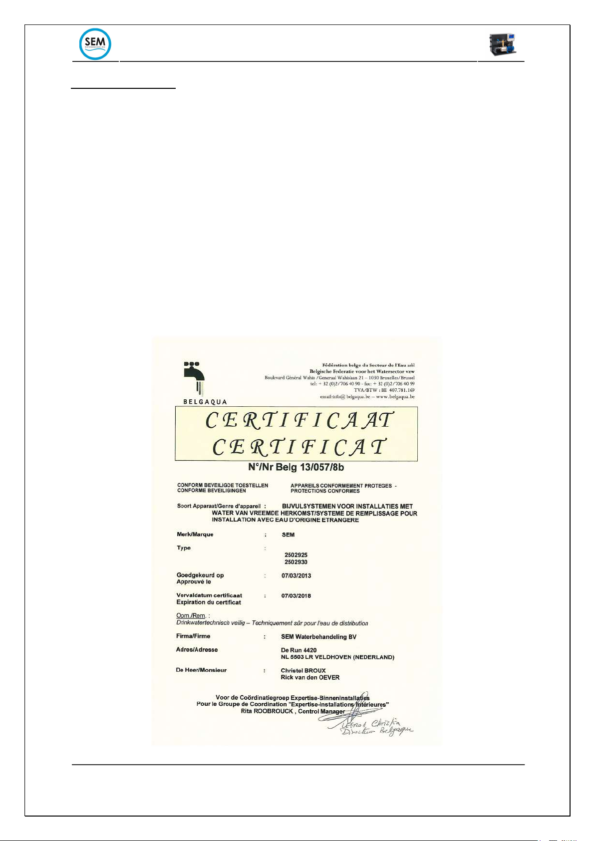
ceases. The SEM Breaktank meets the following standards:
EN1717
Backflow, siphoning and counter pressure are the greatest risks for the quality of drinking water. The
new European standard EN1717 is set up to prevent contaminated water entering the distribution
network of drinking water.
EN1377
A free outlet type "AB" provides a vertical and permanent interruption between the lowest point of
the feed opening and the critical level. The overflow must be non-circular and must be able to
discharge the maximum inlet flow rate under error conditions at positive pressure. Backflow of waste
water (sewage water) into the drinking water network is therefore also excluded

BREAKTANK HA N D B O O K
06/2015 V4.0 3
The SEM Breaktank can be used for the supplementation of a pool. By default, the SEM break tank is
equipped with a universal level control which can measure 1 level. A float switch is supplied to
measure the level in the skimmer or measuring tube. The lift pump has a capacity of 5 to 45 l / min at
11 to 28 m and is protected against dry running. The capacity of the break tank is about 0.8 m³ / hour
with the built-in mechanical float to fill the tank. Optionally, a solenoid valve is available which
increases the filling capacity to 1.5 m³ / hour.
The SEM Breaktank is supplied as standard with a mechanical float to fill the tank and the capacity
is 0.8m³ / hour. See attachment accessories and parts.
This manual contains all information to commission and maintain a SEM Breaktank.
Because the maximum make-up capacity depends on the connection size of the water pipe and the
required head, there may be differences between the capacities mentioned in this manual and the
capacity in your situation.
Warranty limitation
This documentation is provided by SEM Waterbehandeling B.V. She is in no way liable for damage,
direct or indirect, caused by the use of this documentation.
No guarantee is given for suitability for any special applications and parameter settings. SEM Water
treatment B.V. limited visibility to the replacement of parts or documentation to the extent that the
defects are not caused by improper use. For more information see our general delivery and payment
conditions. The guarantee period on this product is 1 year after the date of purchase.
Document rights
This documentation is the property of SEM Waterbehandeling B.V. located in Veldhoven. No part of
this manual may be reproduced or transferred by means of printing, photocopying, electronic
registration or in any manner whatsoever without the prior written permission of the publisher.

BREAKTANK HA N D B O O K
06/2015 V4.0 4
1. Introduction
The SEM Breaktank has been developed for refilling fresh water (supplementation) in a swimming
pool. The water level of the pool is measured with a level switch in eg the buffer, skimmer or level
pipe. If the level is too low, the pump will start and fresh water will be added. The construction of the
Breaktank is such that swimming pool water can never flow back into the pipeline network
(mandatory by the water company). The water supply network must never be operated by a closed
system connected to the pool. This must always be done by means of an open connection.
Specifications of the Breaktank:
• Complete interruption between pool and tap water according to European standard;
• Built-in level control for 1 pool.
• Switch-on delay 15 sec. and switch-off delay of 10 sec. for the level control. Both are adjustable.
This prevents oscillation of the delivery pump due to wave action in the pool.
• Clear display shows status (Run, Standby, Error);
• Simple menu structure (service and setup menu) with LED display and 3 push buttons;
• High Impact Polystyrene (HIPS) reservoir with a capacity of 15 liters;
• Level measurement of the reservoir by means of a pressure sensor. Level is readable in
millimeters in service menu.
• Mechanical float ½ "(approx. 0.8 m³ / hour) or solenoid valve ½" to fill the reservoir (approx. 1.5
m³ / hour).
• Low level protection to protect the feed pump against dry running.
• The self-priming feed pump (0.37kW) has a capacity of 5-45 l / min
with a head from 10 to 28m (with a counter pressure of 1 bar approx. 2.5 m³ / hour). The pump
is equipped with a non-return valve and pressure gauge. Pump is switched with an electronic
relay,
so no danger of sparking or sticking contacts.
• Print is equipped with a relay that switches on water demand. External systems can be
connected to this (max 3A / 230V).
• Glass fuse for electronics (250V / 160mA T) and for pump (250V / 3A T)
• Does not overflow circular, 40x140mm;
• Overflow connection ¾ "F;
• Empty connection with plug ½ ".
• Filling connection 1/2 "F PVC;
• Screw connection for all cabling with removable plugs.
• The Breaktank may only be used for cold water applications, maximum water
temperature 20 ° c.
BREAKTANK HA N D B O O K
06/2015 V4.0 5
2. Control
The Breaktank works completely automatically. Once in operation, the make-up can only be stopped
by shutting down the supply tap if necessary, or by switching off the supply voltage. Of course, the
float switch placed in the pool can also be "manually" influenced by placing it higher or lower relative
to the water level. This will shift the switching point and will eventually change the level of the bath.
The level control is equipped with a switch-on and switch-off delay so that the feed pump can never
"shuttle".
It is also important that the feed pump always runs with a back pressure of at least 1 bar. This is
necessary to let the pump run in its Q / H curve and does not suffer any damage due to overload or
cavitation. The pump pressure can be read on the mounted pressure gauge.
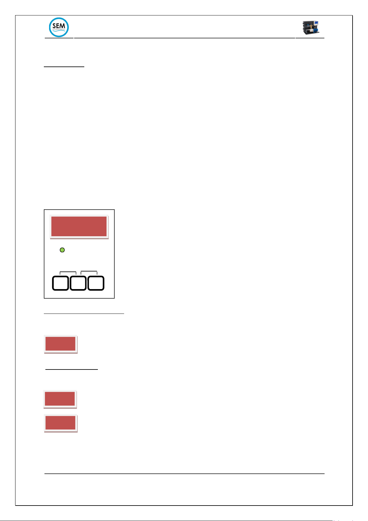
2.1 Display and buttons
The SEM Compact Breaktank is equipped with a digital display. The display shows all relevant
information.
Switch on the power supply:
After switching on the mains voltage, the break tank will show the software version on the display for
3 seconds. Changed settings will always be remembered after a power failure.
Normal operation:
The operating mode is shown on the display, followed by the speed of the pump in%.
StBy = Standby, break tank is standby
RUN= Pump of the break tank is in operation and replenishes the pool
RESET
LOAD
StBy
RUN
RUN
M
+
-
M
+
M
u.
B.
1.3
STATUS

BREAKTANK HA N D B O O K
06/2015 V4.0 6
Alarm notifications:
All alarm messages can be reset by pressing and at the same time, as soon as the fault
has been rectified.
Status light:
The status light is green when the pump is in operation. In the event of a fault, this light will flash red.
= green, pump in operation
= red flashing, fault, the fault code on the display indicates the nature of the fault.
ERR1= water level in the break tank is high, tank is running
ERR2= water level in the break tank is low, pump is blocked against running dry.
ERR3= settings in setup menu are incorrect. Adjust the values of HA, HB, HC, LA, Lb or
Lc.
.
+
M
-
M
ERR 1
300
ERR 2
ERR 3

BREAKTANK HA N D B O O K
06/2015 V4.0 7
2.2. Service menu
The service menu is opened by the button press for > 3 seconds. The decimal point on the
right of the display flashes to indicate that the service menu is active. The menu can be followed by a
short press on the button. The service menu is automatically closed after 10 seconds (except
in menu options L, i1 and i2)
Menuopti
on
Description
Explanation
Operating weeks
Number of weeks that the pump has been in operation
Operating hours
Number of hours the pump has been in operation.
Parameter ‘B’ and ‘U’ together gives the operating time
of the pump. (1 week = 168 hours)
Seri
al number
print
Serial number of the control board
W
ater
level
(Level)
The water level in the break tank is shown measured in
millimeters from the bottom of the tank.
In this mode, the setup menu is not automatically reset
after 10 seconds. so that the water level can be
followed while performing service work.
Input level switch 1
The input level of the input is displayed
0 = contact open (float up)
1 = contact closed (float down)
In this mode, the service menu is not automatically
reset after 10 seconds. so that the input signal can be
followed while performing service work.
Input level switch 2
The input level of the input is
displayed
0 = contact open (float up)
1 = contact closed (float down)
In this mode, the service menu is not automatically
reset after 10 seconds. so that the input signal can be
followed while performing service work.
Input 2 is for optional extensions and not used with the
standard versions
M
M
b. xxx
u. xxx
S. xxx
L. xxx
I1
. x
I2
.
x

BREAKTANK HA N D B O O K
06/2015 V4.0 8
2.3 Setup menu
The setup menu is opened from the service menu. The service menu can be opened to push the the
button >3 seconds. On the right of the display, the decimal point changes from flashing to
continuous edges to indicate that the setup menu is active. The menu can be followed with the
button. With and buttons can be changed values.
The following parameters are adjustable:
The * marked parameters are only applicable in combination with options.
P
arameter
O
mschrijving
Parameters
(factory
setting)
Ta
*
Switching delay time of Level switch Input 2
The switch on the input must at least have the time
parameter ‘Ta’ closed to open KLEP2. This is a solenoid
valve connected to output 2.
This parameter is only applicable if the optional solenoid
valve is used.
t
=0
..
60
s
(
3)
Tb
Switching delay time of Level switch Input 1
This is the switch-on delay time of the level switch that
measures the level of the pool.
The switch at the input must at least have the time
parameter ‘Tb’ closed to start the pump.
t=0
..
60
s
(
15)
Tc
*
Switch
-
off delay time of Level switch Input 2
The switch on the input must at least have the time
parameter ‘Tc’ open to close KLEP2.
This parameter is only applicable if the optional solenoid
valve KLEP2 is used.
t=0
..
60
s
(
1)
Td
Switch
-
off delay time of Level switch Input 1
This is the switch-off delay time of the level switch that
measures the level of the pool.
The switch at the input must at least have the time
parameter ‘Tb’ open to switch off the pump.
t=0
..
0
s(
10)
Ha
*
Filling valve open level in mm
At this level the filling valve is opened and the tank is
refilled.
This parameter is only applicable if the optional solenoid
valve KLEP1 is used.
Ha=0
..
30
c
m
(14)
Hb
*
Filling valve close level in mm
At this level the solenoid valve closes and filling stops
This parameter is only applicable if the optional solenoid
valve KLEP1 is used.
Hb=0
..
30
c
m
(17)
Hc
Critical high level (alarm message Error 1)
If the level of the tank exceeds the value set here, Error 1
will appear on the display.
Hc=0
..
30cm (22)
La
Pump on level (release
pump)
The pump is released when the level in the tank is above
this set level. There is enough water in the tank to prevent
dry running.
La=0..30
cm (
13
)
Lb
Pump off level (pump block
at low water
level
)
Lb=0..30
cm (8
)
M
M
+
M
-
M

BREAKTANK HA N D B O O K
06/2015 V4.0 9
The pump is blocked when the water in the tank comes
below this set level. This is to prevent dry running of the
pump.
Lc
Critical low level (alarm message Error 2)
If the level in the tank falls below the set value set, Error 2
will appear on the display.
Lc=0..30
cm(5)
C
Correction factor
level sensor
With this factor the measured value of the level sensor of
the tank (pressure sensor) can be corrected. Note:
changing this factor influences the operation of the break
tank. Only change in consultation with SEM
Waterbehandeling B.V.
C=0..50%
(10)

BREAKTANK HA N D B O O K
06/2015 V4.0 10
2.4 Schematic representation of menu structure
BREAKTANK HA N D B O O K
06/2015 V4.0 11
!
3. Installation guidelines
When unpacking, check the Breaktank for damage, visible defects, etc. caused by transport. Contact
SEM Water Treatment within 4 working days.
3.1 Hydronic installation
• Place the Breaktank on a flat surface or use the optional wall mounting bracket. Preferably in
the vicinity of a wall socket (230V), a cold water faucet and a sewer connection.
• It is recommended to provide the water supply with a shut-off valve and 500u filter. The
connection size of the water supply is 1/2 "F.
• The connection dimension on the discharge side of the break tank is 25 mm F Glue sleeve.
• The rectangular overflow opening may not be closed.
• The free outlet connection ¾ "F can be connected to a sewer with a 32 mm pipe.
• The drain (drain) connection has a ½ "plug. This allows the tank to be emptied.
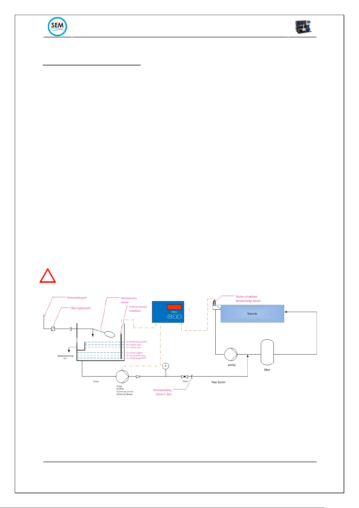
• The installation example below gives a good idea of how the break tank can be connected to
the circulation system. Always ensure that fresh water is added to the filter, but after the
measuring point of the automation (W.H.V.B.Z requirement)
The overflow must always have a free range. The overflow may never be closed. The
breaktank will no longer function properly when the overflow is closed.

BREAKTANK HA N D B O O K
06/2015 V4.0 12
!
3.2 Electrical installation
The SEM Breaktank works on 230V / 50Hz. This tension is life-threatening. Leave the work on
the electrical installation to the professional.
• Provide a wall socket near the Breaktank. Since the break tank is often located in a damp room
(such as boiler houses and engine rooms), it is wise to choose a spray-free type. It is
recommended to connect the Breaktank behind an earth leakage switch.
• If necessary, the wall socket can be switched off by means of protection contacts of, for
example, flowmeters and / or thermal contacts of the swimming pool pumps, etc.
• Use signal cable of at least 2x0.22 mm for the control signal of the float switch. The maximum
cable length may be 50m.
• A connection for two solenoid valves (24Vdc / 8W) has been prepared on the terminal block, for
example:
• 1x solenoid valve: option large capacity (connect to terminal VALVE 1 + 24V and OUT)
• 1x solenoid valve: option n.t. with this model (connection to terminal KLEP2 + 24V and OUT)
• 1x relay contact that switches on water demand, ie as soon as the pump is switched on.

BREAKTANK HA N D B O O K
06/2015 V4.0 13
!
3.3 Commissioning
• Check the level of measuring hose that is placed in the reservoir. This can be shifted by
transport. The hose must be placed at the bottom.
• The pump is below water level and does not need to be filled manually. However, the filler cap
can be loosened for a moment to allow the air to escape. The pump will then self-aspirate.
• Switch on the mains voltage. The display shows the software version for 3 seconds.
• Open the water supply to the tank, the tank will fill up until the high level is reached.
• Check in the service menu whether the tank is filled to 210mm (+/- 5mm). If the level
measurement does not indicate 210mm (+/- 5mm) for a filled container, the measuring hose
must be pulled fully upwards, above the water level and re-inserted into the holder. This is a
calibration of the measuring system. If the level is still not 210mm (+/- 5mm), please contact
SEM Waterbehandeling B.V. After this check the break tank is ready for use.
• If the level switch in the pool is "interrogative" (float down, contact closed) then after a delay
of 15 sec. the pump will start running. If the float of the level switch goes up (float up, contact
open), the pump will switch off after a switch-off delay of 10 seconds. stop. (factory settings)
• If the reservoir is empty, the pump will also switch off (low level reservoir, Lb = 8cm). Only
after the level has risen again above La = 14cm, it will be released again for use, making sure
that the pump is not damaged by running dry.
• Adjust the flow of the pump until the pressure gauge indicates at least 1 bar.
Pay attention:
- Never allow the pump to run dry, always bleed when commissioning.
- It is best to adjust the tap on the pump so that the tank is barely emptied faster by the
pump than that it is filled by the filling connection.
- In the event of frost, the tank and the pump must be completely drained to prevent
damage due to freezing.Let op:

BREAKTANK HA N D B O O K
06/2015 V4.0 14
Characteristics of the feed pump Compact break tank

BREAKTANK HA N D B O O K
06/2015 V4.0 15
3.4 Setting parameters
The following parameters are set as standard on the PLC unit at the factory:
Ta= 3
Tb=15
Tc=1
Td=10
Ha=14
Hb=17
Hc=22
La=13
Lb=8
Lc=5
All factory settings are suitable for normal use. As wished, the parameters can be set differently (see
par. 2.4)
BREAKTANK HA N D B O O K
06/2015 V4.0 16
4. Maintenance and service
In normal use, the break tank requires little maintenance. A few points of interest:
• After being installed or drained, the delivery pump must be vented. To do this, remove the drain
plug from the filler opening at the top of the pump housing. After the pump housing has been
completely filled, the pump can be switched on. Never let the pump run dry!
• Make sure that the feed pump always works with a minimum back pressure of 1 bar. This is to
keep the pump running in its Q / H curve and to prevent damage to seal and impeller.
• The float switch is in a R.V.S. basket built. This is to prevent faults from pollution. However,
grease deposits and small dirt particles can still affect the operation of the float switch
(especially when mounting in a skimmer, for example). From time to time the float should
therefore be inspected.
• Spare parts are always available at SEM Water Treatment.
• The operating hours of the pump can be read in the service menu.

BREAKTANK HA N D B O O K
06/2015 V4.0 17
!
5. Failures
If the pump is not working or not working properly, check the following points to
determine whether or not repair is needed:
Failure
Possible
solution
Solution
Err 1,
tank runs over
Tank is running, level in tank too
high. Mechanical float in the tank is
blocked or does not work properly
Release float or check rubber sealing
ring in the float shut off system
(loosen the red swivel)
Err 2,
level critacal low
Tank leaks or loses water (faster than
tank can be filled) or is drained
empty.
Check the tank for leaks. Check the
tank for siphoning (can occur if tank
is placed higher than pool level)
Err 3
,
parameter
settings H and L
incorrect
Sett
ings entered incorrectly
Check settings in setup menu
The pump runs but
there is no flow, no
Error 2 on display.
Suction pipe is blocked or leaking
Check the suction pipe of the pump
(inlet blocked)
The discharge side of the pump is
blocked (by valve)
Release the pressure side or open
the valve.
No reading on the
display
There is no mains voltage. Fuse
defective
Check the mains voltage using
voltage finder or multimeter. Check
the fuse.
Breaktank control defective
Replace the control print
Well
display readout,
but pump does not
work
Reservoir is empty.
Fuse of the pump is defective
Make sure the reservoir is filled.
Check the pump fuse.
Bath is not refilled,
break tank in order
Float in swimming pool does not
work.
Check float. In service menu, view
parameter 1 or change it from 1 to 0
or vice versa when moving the float
switch. If not, replace the cabling or
float.
In case of other malfunctions contact SEM Water Treatment Technical Department.
Equipment that is contaminated with chemicals or toxic substances that are hazardous to
health is not considered by SEM Water Treatment!
This manual suits for next models
1
Table of contents
Other SEM Industrial Equipment manuals


Popular Industrial Equipment manuals by other brands

Viessmann
Viessmann 4509 Operation manual

Mayr
Mayr EAS-reverse 4100 quick start guide

Outdoor Water Solutions
Outdoor Water Solutions Large Wood Windmill Assembly instructions

Parallax
Parallax RX-101 Instruction booklet

ABB
ABB HT608708 Operation manual

SCHUNK
SCHUNK SRU-plus Series Assembly and operating manual

Monzana
Monzana MZTG124 instructions

BEST ACCESS SYSTEMS
BEST ACCESS SYSTEMS AD432 Service manual

ATOMSTACK
ATOMSTACK R3 Rotary Roller user manual

Eaton
Eaton VoCALL 5 quick start guide

TapFlo
TapFlo DT Series Instructions for installation, operation and maintenance

Nakanishi
Nakanishi RA-271E Operation manual


