TapFlo DT Series Programming manual

Instructions for installation, operation and maintenance for active pulsation dampeners.
STOP
Read this instruction manual carefully,
before you install and operate the pump
Active pulsation dampeners
models:
DT 9/20/25
DT 50/70/80
DT 100/120/125
DT 200/220/225
DT 400/420/425
DT 800/820/825
New DT Series.
IOM MANUAL

IOM manual Active pulsation dampeners 2
CONTENTS
0. GENERAL 4
0.1. Introduction 4
0.2. Warning symbols 4
1. INSTALLATION & SAFETY 5
1.1. Receiving inspection 5
1.2. Storage 5
1.3. Installation of the dampener 5
1.4. Operation principal 6
1.5. Health & Safety 6
1.5.1. Protection 7
1.5.2. Explosion hazardous environments – ATEX 7
1.5.3. Air pressure 7
1.5.4. Noise level 7
1.5.5. Temperature hazards 7
2. MAINTENANCE 8
2.1. When dampener is new or re-assembled 8
2.2. Routine inspection 8
2.3. Location of faults 8
2.4. Dismantling of the dampener 8
2.5. Assembling the dampener 10
3. SPARE PARTS 13
3.1. Spare parts drawing – PE, PTFE and aluminium 13
3.2. Spare parts list – PE, PTFE and aluminium 13
3.3. Spare parts drawing – steel and sanitary 14
3.4. Spare parts list – steel and sanitary 14
3.5. Recommended spare parts 15
3.6. How to order parts 15
4. TECHNICAL DATA 16
4.1. Dimensions 16
4.2. Tightening torques 17
4.3. Dampener code 17
5. WARRANTY & REPAIR 18
5.1. Returning parts 18
5.2. Warranty 18
5.3 Warranty form 20

IOM manual Active pulsation dampeners 3
CE CERTIFICATE
Declaration of conformity
Machinery directive 2006/42/EC
AB declares that:
Product name: Active Pulsation Damener
Models: D T…
Is in conformity with the essential health and safety requirements and technical construction
requirements of the EC Machinery directive 2006/42/EC.
Manufacturer:
Address: Filaregatan 4
S-442 34 Kungälv
Sweden
January 1:st
2014
Håkan Ekstrand
Managing director

IOM manual Active pulsation dampeners 4
0.1 Introduction
The active pulsation dampener is the most efcient way to remove pressure variations on the
discharge of the pump. The Tapo pulsation dampener works actively with compressed air and a
diaphragm, automatically setting the correct pressure to minimise the pulsations. The pulsation
dampener is available for all Tapo pump sizes and material versions.
With proper attention to maintenance, Tapo active pulsation dampeners will give efcient and
trouble free operation. This instruction manual will familiarise operators with detailed information
about installing, operating and maintaining the dampener.
0.2 The warning symbols
The following warning symbols are present in this instruction manual. This is what they say.
This symbol stands next to all safety instructions in this instruction manual where danger
to life and limb may occur. Observe these instructions and proceed with utmost cau-
tion in these situations. Inform also other users of all safety instructions. In addition to
the instructions in this instruction manual, the general safety and accident prevention
regulations must be observed.
This signal stands at points in this instruction manual of particular importance for com-
pliance with regulations and directives, for correct work ow and for the prevention of
damage and destruction of the complete dampener or its subassemblies.
0. GENERAL
!
STOP

IOM manual Active pulsation dampeners 5
1. INSTALLATION & SAFETY
1.1 Receiving inspection
Although precaution is taken by us when packing and shipping, we urge you to carefully check
the shipment on receipt. Make sure that all parts and accessories listed on the packing list are
accounted for. Immediately report any damage or shortage to the transport company and to us.
1.2 Storage
If the equipment is to be stored prior to installation, place it in a clean location. Do not remove the
protective covers from the suction, discharge and air connections which have been fastened to
keep pump internals free of debris. Clean the dampener thoroughly before installation.
1.3. Installation of the dampener
The pulsation dampener is installed according to the sketch. It can be connected with a nipple im-
mediately after the pump outlet, or placed independent of the pump with a exible hose between
the pump and the dampener.
Note! Make sure that the dampener does not cause any tension or strain to the pump.
The dampener should have its own support assembly. Any stress casused by the dampener on
the outlet manifold can result in deformation of parts and leakage of the pump.
The air hose is connected to the pump air hose with a T-connection, between the pump and regu-
lator / valves (See sketch). It is important that the air to the dampener must have the same ow
and pressure as to the pump!
In order to ensure the most effective pulsation dampening the dampener should be installed not
further than ve times the diameter of the pipeline from the discharge ange of the pump - L<5* Ø.
!
!
comp.
AIR
outlet
inlet
L
Ø

IOM manual Active pulsation dampeners 6
1. INSTALLATION & SAFETY
1.4 Operation principal
The pulsation dampener’s main function is to remove pressure variations on the discharge of the
pump. The dampener works actively with compressed air and a diaphragm, automatically setting
the correct pressure to minimise the pulsations.
The air pressure supplied to the dampener is the same as the one supplied to the pump. The
medium owing through the dampener affects the diaphragm, which by means of the compressed
air on the air side compensates the uctuations of pressure in the discharge line. The air concen-
trated in the dampeners block works as a spring for the medium owing through the dampener.
Before starting the pump and dampener.
- Make sure the pump is installed according to the installation instruction.
- When installation is new or re-installed, a test run should be conducted to make sure the
dampener operates normally and does not leak.
- When installation is new or re-installed, check the dampener housing nut tightening torque.
After approx. 1 week of operation, the torque should be checked again. This is important
to prevent leakage.
1.5 Health & Safety
The dampener must be installed according to local and national safety rules.
The dampeners are constructed for particular applications. Do not use the dampener on applica-
tions different from that for which it was sold without consulting Tapo AB to ascertain its suitability.
STOP

IOM manual Active pulsation dampeners 7
1.5.1. Protection
In the interest of health and safety it is essential to wear protective clothing and safety goggles
when operating, and/or working in the vicinity of Tapo dampeners.
1.5.2. Explosion hazardous environments – ATEX
Static electricity may occur in the pump under operation, which may cause explosion
and injury. Special conductive pulsation dampeners DTX are available for such applications.
Follow below instructions and local/national rules for safe use.
ATEX (directive 94/9/EC) classication of Tapo DTX dampeners:
ATEX II 2 GD IIB cT4
Equipment group II – all other explosive areas than mines;
Category group 2 – high level of protection (can be used in zone 1);
Atmosphere G– gas; D– dust;
Explosion group IIB – such as ethylene;
Type of protection c– constructional safety;
Temperature class T4 – in the event of a malfunction, the maximum temperature of a surface that
may be exposed to gas T4 = 135 °C.
Earth connection of dampener and other equipment
Connect a suitable earth wire to the stainless steel earth connection that is placed on the inside
of one of the pump housings. Connect the other end of the earth wire to earth and also make sure
that other equipment like hoses/pipes/containers etc. are properly earthed/connected.
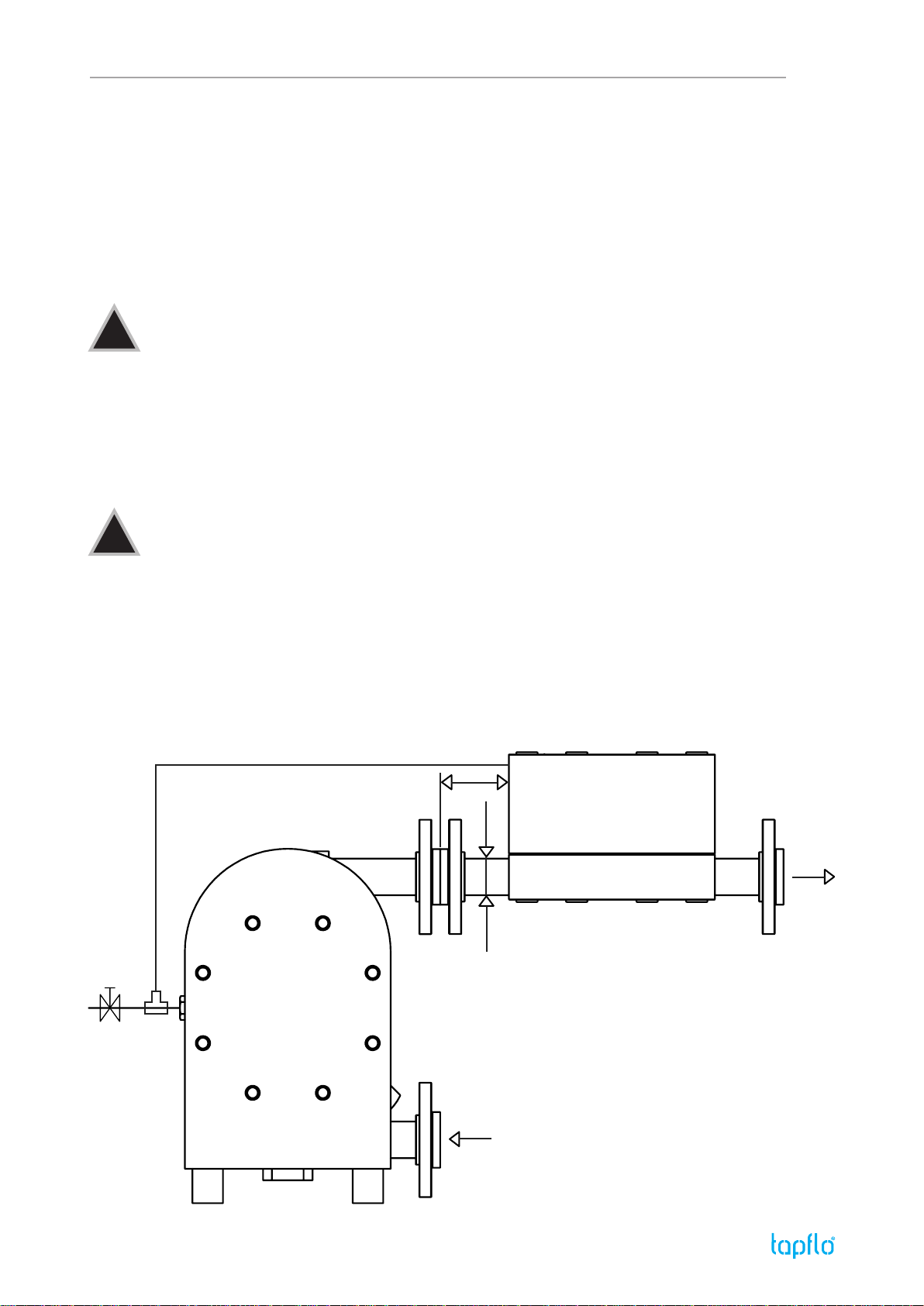
1.5.3. Air pressure
The maximum air pressure for Tapo dampeners is 14 bar. Higher air pressure than 14 bar can
damage the dampener and may cause injury to personnel in vicinity of the dampener.
Please make sure that supply air to the dampener must have the same ow and pressure as the
pump that dampener is installed with.
1.5.4. Noise level
At tests, the noise level from a Tapo dampener has not exceeded 70 dB(A).
1.5.5. Temperature hazards
Raised temperature can cause damage to the dampener and/or piping and may also be hazar-
dous for personnel in the vicinity of the dampener/piping. Avoid quick temperature changes and
do not exceed the maximum temperature specied when the dampener was ordered.
1. INSTALLATION & SAFETY
STOP
STOP
STOP

IOM manual Active pulsation dampeners 8
2. MAINTENANCE
STOP
!
!
Fig. 2.4.1.
By means of a screwdriver, remove the circlip [27] and mufer [25].
Fig. 2.4.2.
Remove the nut covers [579] from the dampener housing and block.
2.1. When dampener is new or re-assembled
If the dampener is new or re-assembled after maintenance it is important to re-tighten the
dampener housing screws (pos. 37) after a few days of operation. Make sure to use the right
torque, see chapter 4.2.
2.2. Routine inspection
Frequent observation of the dampener operation is recommended to detect problems.Achange in
sound of the running dampener can be an indication of wear. Leakage of liquid from the dampener
and changes in performance may also be detected. Routine inspections should be conducted
frequently.
2.3. Location of faults
PROBLEM POSSIBLE FAULT
The dampener does not work The air connection is blocked
The diaphragm is damaged
The mufer is blocked
There is dirt in the dampener chamber
Liquid leaks from the dampener Screws on the housing are not properly tightened
Liquidcomesoutofthemufer The diaphragm is damaged
2.4. Dismantling the dampener
The numbers put in brackets, refer to the part numbers in the spare parts drawing and spare parts
list in chapter 3.
Before the dismantling procedure
Be sure to drain all liquid from the dampener. Cleanse or neutralize the dampener thoroughly.
Disconnect the air connection and then the suction and discharge connections.

IOM manual Active pulsation dampeners 9
2. MAINTENANCE
Fig. 2.4.3.
Using two spanners unscrew the nuts [37] cross-side and take them
out alongside with the washers [38].
Fig. 2.4.4.
Take out the dampener block [12].
Fig. 2.4.5.
Take the pin screws [14] out of the dampener housing [11].
Fig. 2.4.6.
Unscrew the diaphragm [15] by hand (clockwise).
Fig. 2.4.7.
Using an allen key, unscrew the shaft ending [1652] from the di-
aphragm.
Fig. 2.4.8.
Push out the shaft [1651] from the dampener housing.

IOM manual Active pulsation dampeners 10
2. MAINTENANCE
!
Fig. 2.4.9.
Check the inner seals [36] and O-rings [47]. If necessary, take them
out using a screwdriver.
Note! If these parts are removed, they must be replaced with new
ones. If the dampener sealing is worn, also check the shaft for wear
and if necessary replace it.
Fig. 2.5.1.
Using a screwdriver, insert the O-rings [47] into the dampener block
[12].
Fig. 2.5.2.
Using a pair of pliers, insert the seals [36] into the dampener block
[12]. To make the procedure easier bend the seals into a kidney
shape and then t them with a screwdriver.
Fig. 2.5.3.
Push the shaft [1651] into the dampener block [12].
Check all components and clean or repair if necessary. Clean the diaphragm from grease. If the diaphragm
does not need to be replaced, apply grease.
2.5. Assembling the dampener
The numbers put in brackets, refer to the part numbers in the spare parts drawing and spare parts
list in chapter 3.
It is of utmost importance to follow the assembly procedure. If one fails to comply with this proce-
dure, injury or life hazard may occur when operating the dampener.
Assembly procedure

IOM manual Active pulsation dampeners 11
2. MAINTENANCE
!
Fig. 2.5.4.
Screw the shaft ending [1652] into the diaphragm [15].
Note! It is very important to screw the shaft ending(using an allen
key) as deep as possible so it won’t have the tendency to unscrew
during operation.
Fig. 2.5.5.
Screw the diaphragm [15] with the shaft ending [1652] onto the shaft
[1651].
Note! Whenthediaphragm isscrewedin,the holesinthe diaphragm
must be aligned with the holes in the block.
Fig. 2.5.6.
Push the diaphragm [15] in, so that it is touching the dampener
block [12].
Fig. 2.5.7.
Put the pin screws [14] and washers [38]into the dampener housing
[11].
Fig. 2.5.8.
Screw the nuts [37] onto the pin screws [14] so that ca. two threads
are visible over the nut.
Fig. 2.5.9.
Turn over the dampener housing [11] and insert the dampener block
[12] onto the pin screws [14].

IOM manual Active pulsation dampeners 12
2. MAINTENANCE
Fig. 2.5.10.
Insert the washers [38] and nuts [37] on the pin screws [14] from the
side of the block and pre-tighten the nuts cross side.
Fig. 2.5.11.
Tighten the nuts [37] cross-side by means of a torque wrench with
the appropriate torque (see chapter 4.2.).
Fig. 2.5.12.
Insert the nut covers [579] on both sides of the dampener.
Fig. 2.5.13.
Insert the mufer [25] and the circlip [27] in a circular manner.

IOM manual Active pulsation dampeners 13
3. SPARE PARTS
* 4 / 8 in DT 9/20/25A; 6 / 12 in DT 50/70A and DT 100/120A; 8 / 16 in DT 200/220A, DT 400/420A and DT 800/820A
** 6 in DT 100/120A; 3 in the rest
*** only in PTFE execution
3.1 Spare parts drawing – PE, PTFE and aluminium
3.2 Spare parts list – PE, PTFE and aluminium
POS DESCRIPTION QUANTITY
11 Dampener housing 1
113 Threaded insert 4
1173 Reinforcement plate 1 ***
1181 Cover 1 ***
12 Dampener block 1
14 Pin screw 4 / 6 / 8 *
15 Diaphragm 1
1651 Shaft 1
1652 Ending for shaft 1
17 (option) Base 1
174 (option) Socket head cap screw 4
175 (option) Washer 4
179 (option) Rubber foot 4
25 Mufer 1
27 Circlip 1
36 Seal (O-ring) 3
37 Nut 8 / 12 / 16 *
38 Washer 8 / 12 / 16 * PE,AL 4 / 6 / 8 * PTFE
47 O-ring 3 / 6 **
579 Nut cover 8 / 12 / 16 * PE,AL 4 / 6 / 8 * PTFE
70 Flange pipe (threaded) 2
71/73 Looseangering 2
90 Grounding set 1
25 27
579
37
38
12
14
1651
1652
90
47
36
15
11
71/73
70
1173
37
1181
113
179
17
175
174

IOM manual Active pulsation dampeners 14
3. SPARE PARTS
3.3 Spare parts drawing – steel and sanitary
3.4 Spare parts list – steel and sanitary
* 4 in DT 25S; 6 in DT 70S/80 and DT 120S; 8 in DT 220S/225, DT 420S/425 and DT 820S/825
27
25
579
37
38
12
1651
1652
90
14
47
36
15
11
142
37
38
175
174
POS DESCRIPTION QUANTITY
11 Dampener housing 1
12 Dampener block 1
14 Pin screw 4 / 6 / 8 *
142 Washer 4 / 6 / 8 *
15 Diaphragm 1
1651 Shaft 1
1652 Ending for shaft 1
174 (option) Socket head cap screw 1
175 (option) Washer 1
179 (option) Rubber foot 4
25 Mufer 1
27 Circlip 1
36 Seal (O-ring) 3
37 Nut 8 / 12 / 16 *
38 Washer 4 / 6 / 8 *
47 O-ring 3
579 Nut cover 4 / 6 / 8 *
90 Grounding set 1

IOM manual Active pulsation dampeners 15
3. SPARE PARTS
3.5 Recommended spare parts
Even at normal operation some elements in the dampener are subject to wear. In order to avoid
expensive breakdowns we recommend having a few spare parts in stock. These are:
3.6 How to order parts
When ordering spare parts for Tapflo dampeners, it will simplify the process if you give
the model and serial number from the nameplate of the dampener, position number of the part
and quantity.
POS SPARE PART QUANTITY
15 Diaphragm 1
25 Mufer 1

IOM manual Active pulsation dampeners 16
4. TECHNICAL DATA
4.1 Dimensions
I
L
C
X
D
Y
Z
A
P
G
K
B
I
B
L
C
D
AP
PE, PTFE and aluminium dampener
Dimensions in mm (where other is not indicated)
Dimensions in inch (where other is not indicated)
Steel and sanitary dampener
1 PE / PTFE
2 ALU / SS
3 ISO 2852, DIN 11851, SMS1145, BS 4825 (RJT)
* Dimensions for other connections in next table
KG

IOM manual Active pulsation dampeners 17
4. TECHNICAL DATA
4.2 Tightening torques
4.3 Dampener code
4 DIN 2642 , PN 10, loose montage
5 DIN PN10/16 (according to UNI 2277/2278)
6 FLANGE ANSI 150 (according to ASTM-A 182 SO/RF 150 lbs)
7 ANSI B16.5 150 lbs, loose montage
DAMPENER SIZE TIGHTENING TORQUE [Nm]
DT 9/20/25 6
DT 50/70/80 8
DT 100/120/125 16
DT 200/220/225 20
DT 400/420/425 23
DT 800/820/825 30
Tapoactivepulsation
dampener
Special execution:
X = Dampener in conductive
(Ex- zone 0 proof) material
Tapopumpsize(l/min) Material of wetted
dampener housing:
A = Aluminium
P = Polyethylene
S = Stainless steel AISI 316
T = PTFE
Material of diaphragms:
E = EPDM
W = White (food grade) EPDM
N = NBR (nitrile rubber)
T = PTFE
Z = PTFE with white black
DT X 50 P T - 3APL
Special executions*:
3 = Optional connections
5 = Other special executions*
6 = Optional material damper block
9 = Optional material housing screws
11 = Housing reinforcement plate
* = Ask us for complete pump code with all available options and executions. Changes reserved without notice
9/20 30 50 80 100 125 200 225 400 425 800 825
DIN Flange955954955105411551154150515041655165420252004
ANSI 8969078961007108611071276125715261507
--
ISO 2852- 50,5 -50,5-50,5 -64-91
--
DIN 11851-Rd 44x1/6"-Rd 52x1/6"-Rd 65x1/6"-Rd 78x1/6"-Rd 95x1/6"-Rd 110x1/4"
SMS 1145 -Rd 40x1/6"-Rd 40x1/6"-Rd 60x1/6"-Rd 70x1/6"-Rd 85x1/6"- -
(RJT) BS 4825 -Rd 30x1/8"-Rd 46x1/6"-Rd 58x1/6"-Rd 72x1/6"-Rd 98x1/6"- -
DIN FlangeDN155DN154DN155DN204DN255DN254DN405DN404DN505DN504DN805DN804
ANSI 1/2''61/2"71/2''63/4"71''61"71 1/2''61 1/2"72''62"7
--
ISO 2852-DN 25-DN 25-1 1/2" -DN 50 -DN 65
--
DIN 11851- DN 20-DN 25-DN 40-DN 50-DN 65- DN 80
SMS 1145 -1" (25) -1" (25) -1 1/2" (38) -2" (51) -2 1/2"- -
(RJT) BS 4825 -3/4"- 1" -1 1/2"- 2" -3"- -
10 17,3 10 22,9 22 29,7 37 44,3 48 56,3 80 80
0,39 0,68 0,39 0,90 0,87 1,17 1,46 1,74 1,89 2,22 3,15 3,15
-17,1-22,7 -30,1-42,8 -54,8- -
-0,67-0,89 -1,19-1,69 -2,16- -
-22,6-22,6 -35,6- 49 -66- -
-0,89-0,89 -1,40-1,93 -2,60- -
-20-26 -38-50 -66- 81
-0,79-1,02 -1,50-1,97 -2,60- 3,19
-22,6-22,6 -35,6-48,6 -60,6- -
-0,89-0,89 -1,40-1,91 -2,39- -
-15,8-22,2 -34,7-47,6 -73- -
-0,62-0,87 -1,37-1,87 -2,87- -
A
K
DIMENSIONDAMPENER SIZE
DIN Flange
ANSI
ISO 2852
P
DIN 11851
SMS 1145
(RJT) BS 4825

IOM manual Active pulsation dampeners 18
5. WARRANTY & REPAIR
5.1 Returning parts
When returning parts to Tapo AB please follow this procedure:
- Consult Tapo AB for shipping instructions.
- Cleanse or neutralize and rinse the part/dampener. Make sure the part/dampener is
completely empty from liquid.
- Pack the return articles carefully to prevent any damage during transportation.
Goods will not be accepted unless the above procedure has been complied with.
5.2 Warranty
Tapo warrants products under conditions as stated below for a period of not more than 12 months
from installation and not more than 24 months from date of manufacturing.
1. The following terms and conditions apply to the sale of machinery, components and related
services and products, of Tapo (hereinafter “the products”).
2. Tapo (the manufacturer) warrants that:
a. its products as being free of defects in material, design and workmanship at the time of original
purchase;
b. its products will function in accordance with Tapo operative manuals; Tapo does not guaran¬tee
that the product will meet the precise needs of the Customer, except for those purposes set out in
any invitation to render documents or other documents specically made available to Tapo before
entering into this agreement;
c. high quality materials are used in the construction of the pumps and that machining and
as¬sembly are carried out to the highest standards.
Except as expressly stated above, Tapo makes no warranties, express or implied, concerning
the products, including all warranties of tness for a particular purpose.
3. This warranty shall not be applicable in circumstances other than defects in material, design,
and workmanship. In particular warranty shall not cover the following:
a. Periodic checks, maintenance, repair and replacement of parts due to normal wear and tear
(seals, O-rings, rubber items, bushings, etc..);
b. Damage to the product resulting from:
b.1. Tampering with, abuse or misuse, including but not limited to failure to use the product for its
normal purposes as stated at the time of purchase or in accordance with Tapo instructions
for use and maintenance of the product, or the installation or improper ventilation or use of
the product in a manner inconsistent with the technical or safety standard in force;
b.2. Repairs performed by non-skilled personnel or use of non-original Tapo parts
b.3. Accidents or any cause beyond the control of Tapo, including but not limited to lightning,
water, re, earthquake, and public disturbances, etc.;
4. The warrantee shall cover the replacement or repairing of any parts, which is documented
faulty due to construction or assembling, with new or repaired parts free of charges delive-
red by Tapo. Parts subjected to normal tear and wear shall not be covered by the warranty.
Tapo shall decide as to whether the defective or faulty part shall be replaced or repaired.

IOM manual Active pulsation dampeners 19
5. WARRANTY & REPAIR
5. The warrantee of the products shall be valid for a period in accordance to the current law
from the date of delivery, under the condition that notice of the alleged defect to the products
or parts thereof be given to Tapo in written within the mandatory term of 8 days from the
discovery. Repair or replacement under the terms of this warranty shall not give a right to an
extension to, or a new commencement of, the period of warranty.
6. Repair or replacement under the terms of this warranty may be fullled with functionally
equivalent reconditioned units. Tapo qualied personnel shall be solely entitled to carry out
repair or replacement of faulty parts after careful examination of the pump. Replaced faulty
parts or components will become the property of Tapo.
7. The products are built in accordance with standard CE normative and are tested (where
app¬licable) by Tapo. Approval and tests by other control authority are for the customer’s
account. The products shall not be considered defective in materials, design or workmanship
if they need to be adapted, changed or adjusted to conform to national or local technical
or safety standards in force in any country other than that for which the unit was originally
designed and manufactured. This warranty shall not reimburse such adaptations, changes
or adjustments, or attempt to do so, whether properly performed or not, nor any damage re-
sulting from them, nor any adaptation, change or adjustments to upgrade the products from
their normal purpose as described in the products operative manual without the prior written
consent of Tapo.
8. Installation, including electric and other connections to utility mains according to Tapo dra-
wings, is for the cost and responsibility of the customer, unless otherwise agreed in writing.
9. Tapo will not be liable on any claim, whether in contact, tort, or otherwise, for any indirect,
special, incidental, or consequential damages, caused to the customer or to third parties, in-
cluding loss of prots, arising by any possible infringement of par. 3 above or by the customer
or third parties being in the impossibility of using the products.
Steady the above, Tapo liability to the customer or third parties from any claim, whether in contract,
tort, or otherwise, shall be limited to the total amount paid by the customer for the product that
caused the damages.

IOM manual Active pulsation dampeners 20
5. WARRANTY & REPAIR
Company:
Telephone: Fax:
Address:
Country: Contact name:
E-mail:
Delivery date: Dampener was installed (date):
Dampener type: Serial No (stamped on the dampener housing):
Description of the fault:
The installation
Liquid:
Temperature (°C): Viscosity (cPs): Spec. grav. (kg/m3): pH-value:
Contents of particles: %, of max size (mm):
Flow (l/min): Duty (h/day): No of starts per day:
Discharge head (mwc):
Air pressure (bar): Quality of the air (lter, micron?, lubrication?):
Other:
Place for sketch of the installation
5.3 Warranty form
Other manuals for DT Series
1
This manual suits for next models
18
Table of contents
Other TapFlo Industrial Equipment manuals
Popular Industrial Equipment manuals by other brands

Dover
Dover OPW SiteSentinel Integra 100 installation manual

NetterVibration
NetterVibration NTP Series operating instructions

Roller
Roller Robot 2 instruction manual

rbd instruments
rbd instruments IG2 manual

Daikin
Daikin ECORCH 40 Series instruction manual

YZ Systems
YZ Systems DynaPak 2010 Series System Support Manual