BEST ACCESS SYSTEMS AD432 User manual

SERVICE MANUAL
SERVICE MANUAL

CREDITS/COPYRIGHT
©2001 Best Lock Corporation dba Best Access Systems. All rights reserved. Printed in
the United States of America.
Information in this document is subject to change without notice and does not
represent a commitment on the part of Best Access Systems. The software described in
this document are furnished under a license agreement or nondisclosure agreement.
This publication is intended to be an accurate description and set of instructions
pertaining to its subject matter. However, as with any publication of this complexity,
errors or omissions are possible. Please call your BEST distributor or Best Access
Systems at (317) 849-2250 if you see any errors or have any questions. No part of this
manual and/or databases may be reproduced or transmitted in any form or by any
means, electronic or mechanical, including photocopying, recording, or information
storage and retrieval systems, for any purpose, without the express written permission
of Best Access Systems.
This document is distributed as is, without warranty of any kind, either express or
implied, respecting the contents of this book, including but not limited to implied
warranties for the publication’s quality, performance, merchantability, or fitness for any
particular purpose. Neither Best Access Systems, nor its dealers or distributors shall be
liable to the user or any other person or entity with respect to any liability, loss, or
damage caused or alleged to be caused directly or indirectly by this publication.
The Life Safety Code is a registered trademark of the National Fire Protection
Association.
Written and designed by Best Access Systems and Avalon Group, Inc., Indianapolis,
Indiana.
T61804 Rev – 1837172 ER7991-6 October 2001

Key Combinator Service Manual iii
CONTENTS
FIGURES V
GETTING STARTED 1–1
Introduction 1–1
Product family diagram 1–2
Documentation package 1–3
Technical support 1–3
Support services 1–3
Telephone and web technical support 1–3
Training seminars 1–3
PARTS 2–1
Exploded diagram of a key combinator—left hand 2–2
Exploded diagram of a key combinator—right hand 2–3
Key options 2–4
Standard key 2–4
Premium key 2–4
Patented key 2–4
Keyway options 2–5

Contents
iv Key Combinator Service Manual
SERVICE AND MAINTENANCE 3–1
Combinator handing 3–2
Left-handed vs. right-handed combinators 3–2
Maintenance tools 3–2
BEST tools 3–2
Additional tools 3–3
Cutting keys 3–4
Loading the key 3–4
Cutting the key 3–5
Unloading the key 3–6
Converting the combinator between the A2, A3, and A4 systems 3–7
Replacing the depth selector 3–7
Replacing parts 3–9
Replacing the punch and die 3–9
Replacing the key carriage 3–11
Replacing the operating lever 3–13
Calibrating the key combinator 3–16
Cutting a calibration key 3–16
Placing the key in the gauge 3–18
Reading the gauge 3–18
Totaling the measurement 3–19
Checking the measurement 3–19
Adjusting the depth selector 3–20
Adjusting the key clamp spring 3–25
Preventative maintenance 3–27
Cleaning parts 3–27
Cleaning the punch and die 3–27
Cleaning the key carriage 3–27
Lubricating parts 3–28
Guidelines for lubrication 3–28
Lubricating the key combinator housing 3–28
Troubleshooting 3–31
GLOSSARY A–1
PREVENTATIVE MAINTENANCE B–1
INDEX C–1

Key Combinator Service Manual v
FIGURES
GETTING STARTED
Key combinator product family 1–2
PARTS
LH key combinator 2–2
RH key combinator 2–3
Standard key blank 2–4
Premium key blank 2–4
Patented key blank 2–4
SERVICE AND MAINTENANCE
BEST maintenance tools 3–2
Loading a key 3–4
Key in the key clamp spring 3–5
Cutting a key 3–6
Removing the depth selector 3–7
Reinstalling the depth selector 3–8
Punch and die assembly 3–9
Inserting the punch into the T-slot 3–10
Removing the key carriage 3–11
Reinstalling the key carriage 3–12
Depressing the key carriage plungers 3–13
Removing the operating lever 3–14
Reinstalling the operating lever 3–15
Cutting a calibration key 3–17

Figures
vi Key Combinator Service Manual
Inserting a key into the key gauge 3–18
Calibration measurement scale 3–19
Marking the depth selector assembly 3–20
Loosening the spanner nut 3–21
Turning the depth adjuster counterclockwise 3–22
Turning the depth adjuster clockwise 3–23
Loading a key 3–25
Adjusting the key clamp spring 3–26
Lubricating parts 3–29
Lubricating the punch and die 3–30

Key Combinator Service Manual 1–1
1GETTING STARTED
INTRODUCTION
The Key Combinator Service Manual contains
essential information to help you maintain your BEST
key combinator.

Getting Started
1–2 Key Combinator Service Manual
PRODUCT FAMILY DIAGRAM
Figure 1.1 Key combinator product family
CAUTION
PINCH POINT
ALIBRATE
YSTEMA2
Patented key blank
Premium key blank
Standard key blank
Spanner wrench
Calibration gauge
Key combinator
Chip tray
Circlip pliers

Getting Started
Key Combinator Service Manual 1–3
DOCUMENTATION PACKAGE
The following documentation is available to help you with the
installation, operation, and maintenance of your BEST key combinator
along with associated service equipment. These documents also can be
ordered separately from the product.
TECHNICAL SUPPORT
Support
services
When you have a problem with a BEST key combinator, your first
resource for help is the Key Combinator Service Manual. If you cannot
find a satisfactory answer, contact your local BEST Representative.
Telephone and
web technical
support
A factory-trained Certified Product Specialist (CPS) is available in your
area whenever you need help. Before you call, however, please make
sure that the product is in your immediate vicinity, and that you are
prepared to give the following information:
■what happened and what you were doing when the problem arose
■what you have done so far to correct the problem.
Best Access Systems Representatives provide telephone technical
support for key combinators and related products. You may locate the
representative nearest you by calling (317) 849-2250 Monday through
Friday, between 7:00 a.m. and 4:00 p.m. eastern standard time; or visit
the web page, www.BestAccess.com.
Training
seminars
Best Access Systems regularly holds factory training seminars for
owners of BEST masterkey systems. Your BEST Representative may hold
regular seminars as well. Contact your representative for information on
these seminar opportunities.
Document Title Doc. No.
Core and Key Service Manual T35527
Operating Instructions for AD432 Key Combinator T35531
Operating Instructions for AD433 Key Combinator T35529
Operating Instructions for AD502 Micrometer Key Gauge T35530

Getting Started
1–4 Key Combinator Service Manual

Key Combinator Service Manual 2–1
2 PARTS
The following pages contain descriptions and figures
for the key combinator.

Par
t
s
2–2 Key Combinator Service Manual
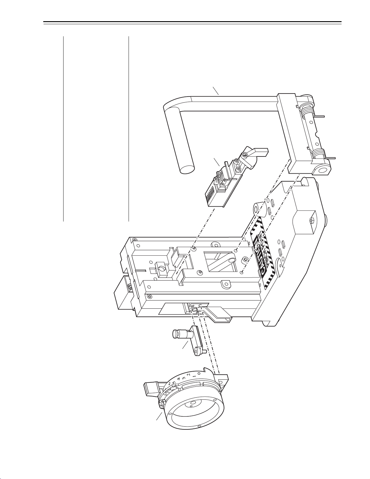
EXPLODED DIAGRAM OF AKEY COMBINATOR—LEFT HAND
Figure 2.1 LH key combinator
CALIBRAT
SYSTEM A
Item†Part No. Qty. Description
1 A70595 1 Operating lever assembly
2
not shown
not shown
C70580
C70610
C70601
1
1
1
Premium key carriage
Key carriage for BEST/Peaks—7-pin
Key carriage for BEST/Peaks—6-pin
3
not shown
B70341
B70625
1
1
Punch and die assembly
Punch and die assembly for BEST/Peaks
4
not shown
not shown
A70325
A70326
A70327
1
1
1
Depth selector assembly—A2
Depth selector assembly—A3
Depth selector assembly—A4
†Seepage 3–7 for instructions on converting between the A2, A3, and
A4 Systems.
1
2
3
4
Par
t
s
Key Combinator Service Manual 2–3
EXPLODED DIAGRAM OF AKEY COMBINATOR—RIGHT HAND
Figure 2.2 RH key combinator
ALIBRATE
YSTEMA2
Item†Part No. Qty. Description
1
not shown
not shown
C70322
C70323
C70324
1
1
1
Depth selector assembly—A2
Depth selector assembly—A3
Depth selector assembly—A4
2 B70341 1 Punch and die assembly
3
not shown
C70578
C70579
1
1
Standard key carriage
Premium key carriage
4 A70591 1 Operating lever assembly
†Seepage 3–7 for instructions on converting between the A2, A3, and
A4 Systems.
1
2
34

Parts
2–4 Key Combinator Service Manual
KEY OPTIONS
The following key options are offered by BEST. Refer to the Core and
Key Service Manual (T35527) for ordering information.
Standard key Standard keys are cut by the AD433 key combinator.
Premium key Premium keys are cut by the AD433P key combinator.
Patented key PEAKS patented keys are cut by the AD437 and AD436 key combinator.
Figure 2.3 Standard key blank
Figure 2.4 Premium key blank
Figure 2.5 Patented key blank

Parts
Key Combinator Service Manual 2–5
KEYWAY OPTIONS
The following section lists BEST keyways and the combinators that
must be used to cut the keys.
Note: BEST key combinators are available only to registered BEST
customers who currently have the A2, A3, or A4 masterkey system. For
more information, contact your local BEST Representative.
Standard keyways
All standard keyways require a RH configuration for the key
combinator.
Premium keyways
Some premium keyways require a LH configuration for the key
combinator and some require a RH configuration. See the table below.
Patented keyways
All patented keyways require a LH configuration. The B1 and B2
keyways are the only Peaks keyways available to use with the AD437
and AD436 key combinators.
Configuration Keyway
RH WA
WB
WC
WG
WH
WK
WY
LH WD
WE

Parts
2–6 Key Combinator Service Manual

Key Combinator Service Manual 3–1
3 SERVICE AND MAINTENANCE
This chapter contains instructions for servicing and
maintaining key combinator components, and a
section for troubleshooting common problems.
To
See
page
Understand combinator handing 3–2
Look at maintenance tools 3–2
Cut keys 3–4
Convert your combinator between A2,
A3, and A4 systems
3–7
Replace the punch and die 3–9
Replace the key carriage 3–11
Replace the operating lever 3–13
Calibrate the key combinator 3–16
Adjust the key clamp spring 3–25
Create a preventative maintenance plan 3–27
Clean the punch and die 3–27
Clean the key carriage 3–27
Lubricate parts 3–28
Troubleshoot common problems 3–31

Service and Maintenance
3–2 Key Combinator Service Manual
COMBINATOR HANDING
Left-handed vs.
right-handed
combinators
The terms “left-handed” and “right-handed” describe the handing of a
combinator, but this is not a convenience feature for left-handed or
right-handed individuals. The handing on a combinator is distinguished
by the position of its operating lever. The operating lever position
determines which types of keys the combinator can cut.
Left-handed key combinator
When facing the combinator, the operating handle is attached to the
left side of the left-handed or LH key combinator. A LH key combinator
cuts patented or left-handed premium keys. It does not cut standard
keys.
Right-handed key combinator
When facing the combinator, the operating handle is attached to the
right side of the right-handed or RH key combinator. A RH key
combinator cuts premium or right-handed standard keys. It does not cut
patented keys.
To determine which keys are appropriate for your security needs,
contact your BEST Representative. See page 2–5 for more information
on key combinators and their keyway types.
MAINTENANCE TOOLS
BEST tools The following tools are provided by BEST for servicing your key
combinator.
Maintenance tools parts list
Figure 3.1 BEST maintenance tools
12 3
Item
Nomen-
clature Part No. Qty. Description
1
not shown
AD502
AD502D
B70564
B70574
1
1
Key calibration gauge—standard
Key calibration gauge—digital
2 A70558 1 Spanner wrench
3 HT03009 1 Circlip pliers

Service and Maintenance
Key Combinator Service Manual 3–3
Additional tools The following Allen wrenches are used for servicing your key
combinator:
■3/32″
■7/64″
■1/8″
■9/64″
■5/32″
■3/16″.
Service and Maintenance
3–4 Key Combinator Service Manual
CUTTING KEYS
BEST recommends that you secure your key combinator to a flat surface
before you begin cutting keys. You can install bolts either through each
of the rubber feet or through two holes on the base of the combinator.
Contact BEST for further instructions.
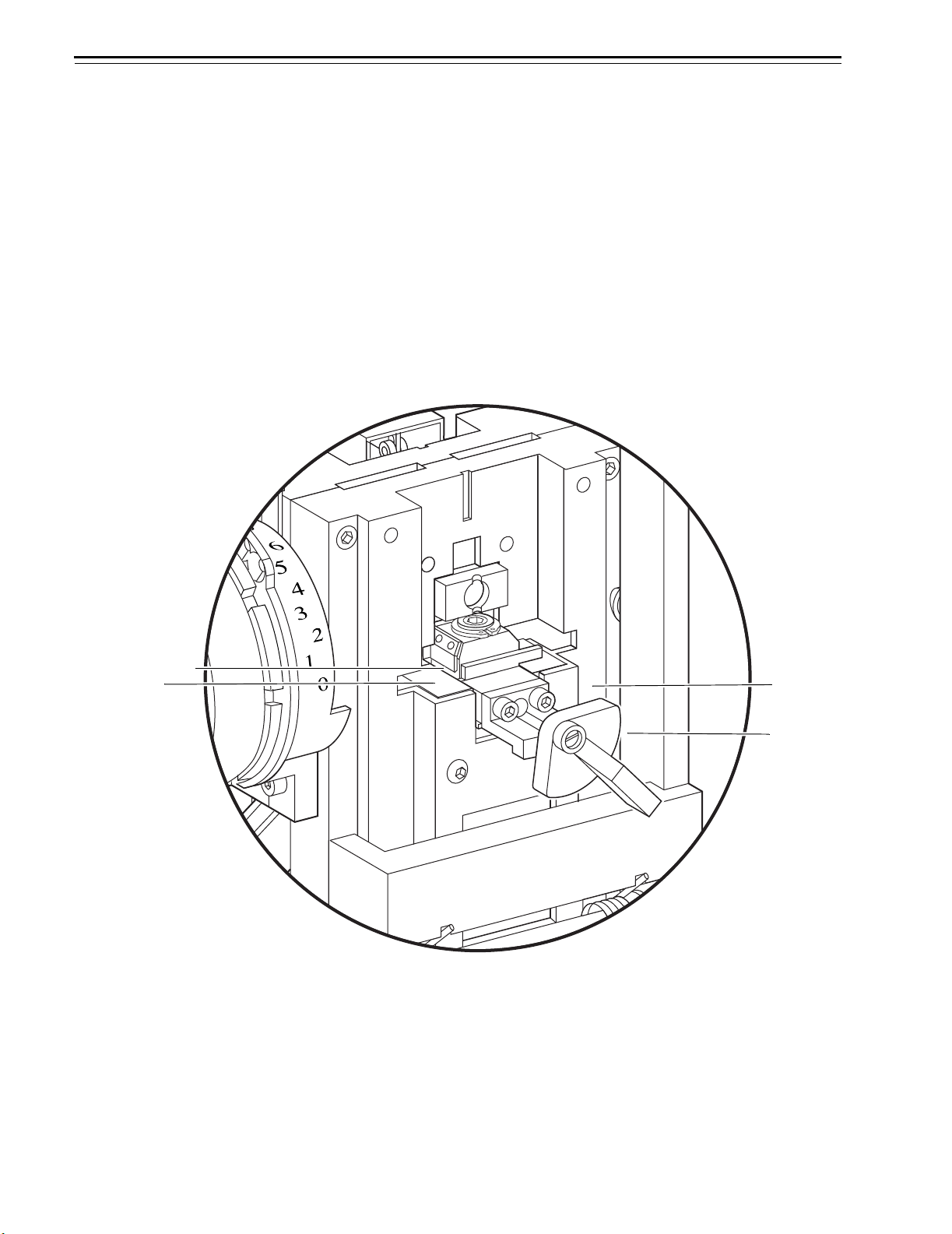
Loading the key To load a BEST standard key blank:
1. Gripping the key clamp knob, pull the key carriage completely
forward.
2. Turn the key clamp knob counterclockwise to open the key clamp
spring (for left-handed combinators, turn the key clamp knob
clockwise). See Figure 3.2.
3. With the curved edge of the key blank against the locating surface,
slide the key blank into the key opening. Make sure that the knife
edge of the key clamp spring fits into the groove of the key. See
Figure 3.3.
Figure 3.2 Loading a key
ALIBRATE
YSTEM A2
Key
carriage
Key clamp
knob
Front view of combinator
Key opening
Locating surface
This manual suits for next models
5
Table of contents
Popular Industrial Equipment manuals by other brands

INOXPA
INOXPA INNOVA Mini N Installation, service and maintenance instructions

Siemens
Siemens Flender FLUDEX 4600 Series operating instructions

Schmalz
Schmalz SBP Series operating instructions

Continental Refrigerator
Continental Refrigerator PC125-RCD Operator's manual

WCS
WCS Dumpster Assembly instructions

ABB
ABB HT591736 Operation manual


