SEMROC KV-66 User manual

24
1. Materials. I will use only lightweight, non-metal parts for the nose,
body, and fins of my rocket.
2. Motors. I will use only certified, commercially-made model rocket
motors, and will not tamper with these motors or use them for any
purposes except those recommended by the manufacturer.
3. Ignition System. I will launch my rockets with an electrical launch
system and electrical motor igniters. My launch system will have a
safety interlock in series with the launch switch, and will use a launch
switch that returns to the "off" position when released.
4. Misfires. If my rocket does not launch when I press the button of
my electrical launch system, I will remove the launcher's safety inter-
lock or disconnect its battery, and will wait 60 seconds after the last
launch attempt before allowing anyone to approach the rocket.
5. Launch Safety. I will use a countdown before launch, and will
ensure that everyone is paying attention and is a safe distance of at
least 15 feet away when I launch rockets with D motors or smaller,
and 30 feet when I launch larger rockets. If I am uncertain about the
safety or stability of an untested rocket, I will check the stability be-
fore flight and will fly it only after warning spectators and clearing
them away to a safe distance.
6. Launcher. I will launch my rocket from a launch rod, tower, or rail
that is pointed to within 30 degrees of the vertical to ensure that the
rocket flies nearly straight up, and I will use a blast deflector to pre-
vent the motor's exhaust from hitting the ground. To prevent acciden-
tal eye injury, I will place launchers so that the end of the launch rod
is above eye level or will cap the end of the rod when it is not in use.
7. Size. My model rocket will not weigh more than 1,500 grams (53
ounces) at liftoff and will not contain more than 125 grams (4.4
ounces) of propellant or 320 N-sec (71.9 pound-seconds) of total
impulse. If my model rocket weighs more than one pound (453
grams) at liftoff or has more than four ounces (113 grams) of propel-
lant, I will check and comply with Federal Aviation Administration
regulations before flying.
8. Flight Safety. I will not launch my rocket at targets, into clouds, or
near airplanes, and will not put any flammable or explosive payload
in my rocket.
9. Launch Site. I will launch my rocket outdoors, in an open area at
least as large as shown in the accompanying table, and in safe
weather conditions with wind speeds no greater than 20 miles per
hour. I will ensure that there is no dry grass close to the launch pad,
and that the launch site does not present risk of grass fires.
10. Recovery System. I will use a recovery system such as a
streamer or parachute in my rocket so that it returns safely and un-
damaged and can be flown again, and I will use only flame-resistant
or fireproof recovery system wadding in my rocket.
11. Recovery Safety. I will not attempt to recover my rocket from
power lines, tall trees, or other dangerous places.
LAUNCH SITE DIMENSIONS
Installed Total Impulse
(N-sec)
Equivalent Motor Type Minimum Site Dimensions
(ft.)
0.00 —1.25 1/4A 50
1.26 —2.50 A 100
2.51 —5.00 B 200
5.01 —10.00 C 400
10.01 —20.00 D 500
20.01 —40.00 E 1000
40.01 —80.00 F 1000
80.01 —160.00 G 1000
160.01 —320.00 2 Gs 1500
1
Made in the U.S.A by Semroc Astronautics Corporation - Knightdale, N.C. 27545
Orbital Transport™
Kit No. KV-66
NASA INSPIRED
EASY AND FUN
TO BUILD
EXCITING
FLIGHTS
BALSA
NOSE
CONES
Engines
B6-4
C6-5
Specifications Booster Glider
Body Diameter 0.976” (2.5 cm) 0.736” (1.9 cm)
Length 23.0” (58.4 cm) 8.6” (21.8 cm)
Fin Span 8.1” (20.6 cm) 5.4” (13.7 cm)
Net Weight 1.8 oz. (51.1 g) 0.5 oz. (14.2 g)
Glide/Parachute Recovery
Designed by:
Wayne Kellner
TM
2
Copyright © 2008 Semroc Astronautics Corporation
Box 1271 Knightdale, NC 27545 (919) 266-1977
September 28, 2008
What is a Retro-Repro?
A Retro-Repro™ is a reproduction of an out-of-
production model rocket kit. It is a close ap-
proximation of a full scale model of an early
historically significant model rocket kit from
one of the many companies that pioneered the
hobby over the past half century. A Retro-
Repro™ is not a true clone or identical copy of
the original. It incorporates improvements us-
ing modern technology, while keeping the fla-
vor and build appeal of the early kits.
About
Estes Industries, Inc.
In July 1958, G. Harry Stine of Model Missiles,
Inc. in Denver, Colorado approached Vern Es-
tes about making model rocket engines for
them. On January 15, 1959, Vern’s automated
model rocket engine fabricating machine,
“Mabel”, produced the first of many millions
of Estes model rocket engines. In 1960, Estes
was producing more engines than Model Mis-
siles could sell. Vern and his wife Gleda
opened a mail order rocket company and intro-
duced the Astron Scout and Astron Mark.
In 1961, a catalog was mimeographed and
hand stitched on Gleda’s sewing machine.
Later that year, Estes Industries had outgrown
the confined space in Denver. In December
1961, the entire operation was moved to an old
farm in Penrose, Colorado quickly establishing
the small town as the “Model Rocket Capital of
the World.”
Estes Industries was sold to Damon in Septem-
ber 1969. The name Estes is synonymous with
model rocketry. Almost everyone remembers
growing up firing Estes rockets or knowing
someone that did. Estes Industries has intro-
duced millions of youngsters of all ages to
model rocketry for almost half a century.
23
If you are not 100% satisfied with your Semroc
product, we will make it right by providing what-
ever you consider fair, from refund to replacement.
Contact us at:
Semroc Astronautics Corporation
Customer Service Department
P.O. Box 1271
Knightdale, North Carolina 27545
100% SATISFACTION
GUARANTEE
LIMITATION OF LIABILITY
Model rockets are not toys, but are functional rock-
ets made of lightweight materials and are launched
with NAR or Tripoli safety certified model rocket
motors, electrically ignited and flown in accordance
with the NAR Model Rocket Safety Code. If mis-
used, model rockets can cause serious injury and
property damage. Semroc certifies that it has exer-
cised reasonable diligence in the design and manu-
facture of its products. Semroc cannot assume any
liability for the storage, transportation, or usage of
its products. Semroc shall not be held responsible
for any personal injury or property damage whatso-
ever arising out of the handling, storage, use, or
misuse of our products. The buyer assumes all risks
and liabilities therefrom and accepts and uses Sem-
roc products on these conditions.
Your purchase and use of any Semroc products is
construed as your agreement to and acceptance of
these terms. If you do not agree to these terms and
conditions, you must return the product, unused,
for refund or credit.
JOIN THE NAR!
Sign up online at www.nar.org to join
the premier model rocketry organiza-
tion. Semroc fully supports the Na-
tional Association of Rocketry and rec-
ognizes it as the sport’s official voice.
The NAR is the oldest and largest
sport rocketry organization in the
world. Since 1957 over 80,000 serious
sport rocket modelers have joined the
NAR to take advantage of the fun and
excitement of organized rocketry. It is always more
fun if you fly with friends. The Sport Rocketry
magazine is one of the best ways to keep informed
of new developments in the hobby. Check online at
www.semroc.com/nar for promotions just for NAR
members.
22
FLIGHT PREPPING
53. The B4-4 and C6-5 are the two recom-
mended engines for the Orbital Transport™. Insert
it into the booster and make sure the engine hook
will retain it.
58. Carefully check all parts of your rocket
before each flight as a part of your pre-flight check-
list. Launch the Orbital Transport™from a 1/8” di-
ameter by 36” long launch rod. Always launch in a
vertical position in calm winds. Use the smaller en-
gine for the first flights.
57. Refer to the model rocket engine manu-
facturer’s instructions to complete the engine prep-
ping. Different engines have different igniters and
methods of hooking them up to the launch control-
lers.
54. Pack the recovery wadding from the top
of the body tube. Use a sufficient quantity to protect
the parachute, but not too much that there is no
room left.
55. Fold the parachute and pack it and the
shock cord on top of the recovery wadding. Slide
the nose cone into place, making sure it does not
pinch the shock cord or parachute.
56. Attach the glider to the booster by hook-
ing the hold-down support on the bottom of the
glider into the launch lug on the top of the booster.
The glider should rest on the glider supports when
held in a vertical position.
3
TOOLS: In addition to the parts supplied, you will
need the following tools to assemble and finish
this kit. Masking tape and wax paper are also re-
quired.
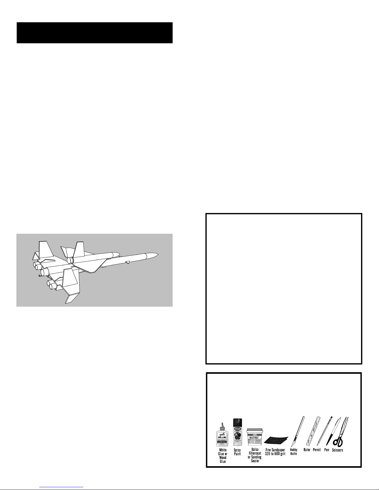
About the Orbital Transport™
The Estes Orbital Transport was introduced in
Catalog #683 in late 1968. It was designed by
Wayne Kellner, one of the most prolific and
innovative designers at Estes Industries. The
Orbital Transport was based on an early NASA
scramjet design for the Space Shuttle. It fea-
tured a parasite glider that deployed at ejection
and parachute recovery for the booster. The
Orbital Transport was released as Cat. No. K-42
and had an introductory price of $2.50.
The Semroc Retro-Repro™Orbital Transport™
is very close to the original with some modern
changes. The original balsa nose cones are
kept. All fins are precision laser-cut balsa. A
Kevlar shock cord mount is added for better
retention. The original rubber shock cord is re-
placed with elastic. The 18” parachute is re-
duced to 12” for less drift.
BEFORE YOU START!
Make sure you have all the parts included in this kit
that are listed in the Parts List in the center of these
instructions. In addition to the parts included in this
kit, you will also need the tools and materials listed
below. Read the entire instructions before begin-
ning to assemble your rocket. When you are thor-
oughly familiar with these instructions, begin con-
struction. Read each step and study the accompa-
nying drawings. Check off each step as it is com-
pleted. In each step, test-fit the parts together be-
fore applying any glue. It is sometimes necessary
to sand lightly or build-up some parts to obtain a
precision fit. If you are uncertain of the location of
some parts, refer to the exploded view in the cen-
ter of these instructions. It is important that you
always ensure that you have adequate glue joints.

4
1. These instructions are presented in a logical
order to help you put your Orbital Transport™to-
gether quickly and efficiently. Check off each step
as you complete it and we hope you enjoy putting
this kit together.
ASSEMBLY
2. There are many different balsa parts in-
cluded in this kit. Use the guide below to identify
the parts that are called out in these instructions.
Some of the parts are similar, but will not work if
exchanged. Sheet A and Sheet B are similar, except
the main wing parts (1) and (2) are mirror images
for left and right. The balsa parts will be referred as
(#) in these instructions.
PARTS IDENTIFICATION
3. Lightly sand each side of the laser-cut balsa
fin sheet. Carefully push the laser-cut fins from the
sheet. Start at one point on each fin and slowly and
gently work around the fin.
BALSA PREPARATIONS
21
GLIDE TRIMMING
52. Locate a clear grassy area free of objects
that will damage your glider. Face the wind and
gently toss the glider with a slight angle of attack
upward. The elevons may be adjusted with a little
heat applied to the glue joint using a light bulb or
hair dryer on low heat. If the glider stalls, lower
both flaps and try again. If it dives, raise the elevons
slightly and retry. If it dives, lower them slightly. If it
turns in flight, lower the elevon on the side that
turns until it glides straight. If you have a very small
field, you may want the glider to turn to stay in the
area.
51. After the paint has dried, decals should be
applied. The decals supplied with the Orbital Trans-
port™are waterslide decals. Refer to the photo on
the front and the diagram below for decal place-
ment. Check for fit before wetting the decal. A drop
of detergent in the water will allow for more move-
ment before the decal sets.

20
48. When the fillets have dried, prepare balsa
for a smooth professional looking finish. Fill the
wood grain with Fill’n’Finish, balsa fillercoat, or
sanding sealer, When dry, sand with fine sandpa-
per. Repeat until smooth. Don’t overdo it! Layers of
unsanded filler can add much weight!
FINISHING
49. After all balsa surfaces have been pre-
pared, wipe off all wood dust with a dry cloth. First
spray the model with an enamel primer, then spray
both the booster and glider gloss white.
50. Spray painting your model with a fast-
drying enamel will produce the best results. PA-
TIENCE…is the most important ingredient. Use sev-
eral thin coats, allowing each coat to completely dry
before the next coat. Start each spray a few inches
above the model and end a few inches below the
model. Keep the can about 12” away and use quick
light coats. The final coat can be a little heavier to
give the model a glossy wet-looking finish.
5
5.Glue the main wing sections (1) and (2) to-
gether from one sheet with the etched lines to the
top. Align section 2 so it achieves a square fit with
section 1. Use wax paper over a flat surface to keep
it from sticking. Repeat for the other wing and allow
the main wing assemblies to dry completely.
BOOSTER ASSEMBLY
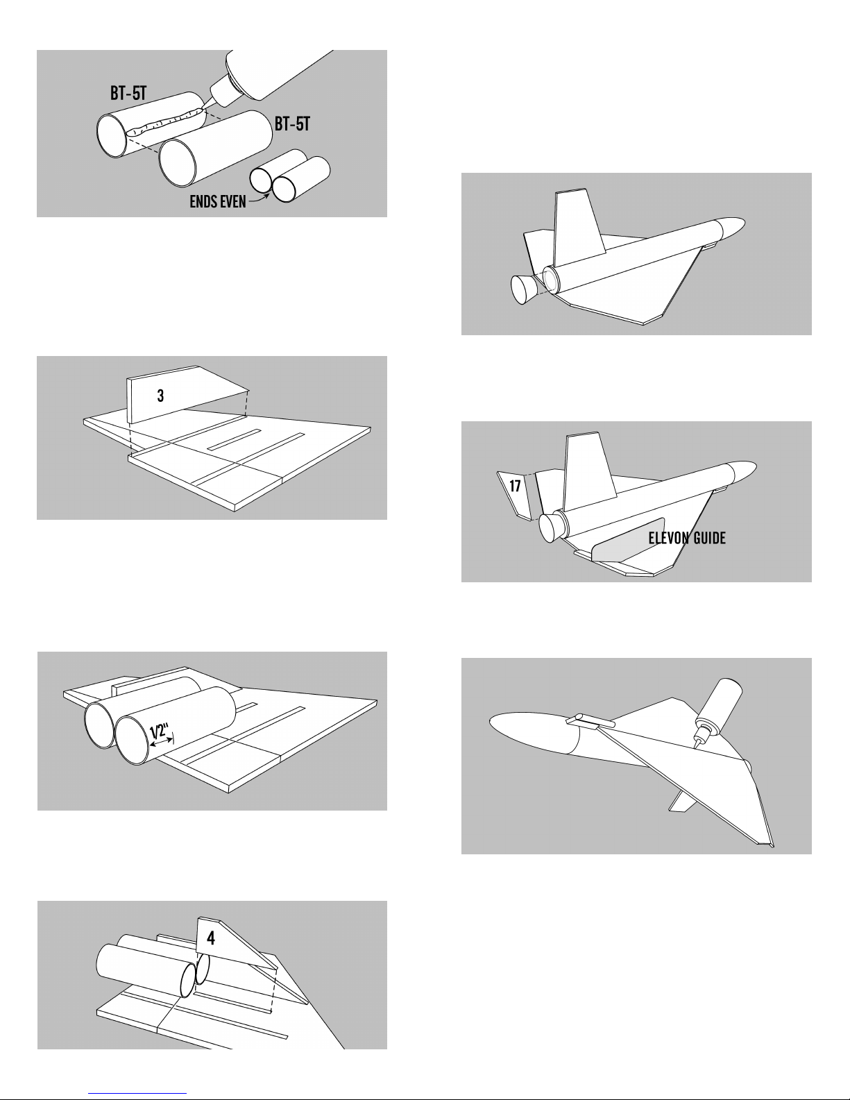
6. Apply a bead of glue along one side of one
of the BT-5T body tubes. Attach a second BT-5T to
the glue line. Align the ends and allow to dry on a
flat surface. Repeat with the other pair of BT-5T
body tubes and allow both assemblies to dry.
4. Stack all the like fins in groups. Line each
group up squarely and sand the fins back and forth
over some fine sandpaper to get rid of the hold-in
tabs as shown below.
6
8.Mark one pair of the scramjet tube assem-
blies 1/2” from one end. Glue the long (forward)
ends of the tubes to the main wing with 1/2” over-
hanging and one side against the outboard hous-
ing. Check that the mark is even with the trailing
edge of the wing and allow to dry.
7. Locate the scramjet outboard housing (3)
and sand the leading edge to a round shape. Note
that Part (3) and part (6) are identical. Apply a bead
of glue along the outermost line on one of the wing
assemblies. Align the housing so it is even with the
trailing edge of the main wing and perpendicular to
the surface.
9.Sand the leading edge of the intake vane (4)
round and glue it in front of the scramjet tubes and
on the lines provided on the main wing and allow
to dry.
19
46.Attach the elevons (17) to the trailing
edges of the glider wings. Use the Elevon Guide to
get the correct angle as shown.
47.Apply a bead of glue along the lower
wing joint. Do not use any more glue than neces-
sary.
45.Apply a thin bead of glue around the
small end of the shroud and attach it to the center
of the paper nose block on the end of the glider.
When it is dry, run a heavier bead around the inside
of the ring at the joint. Using a small amount of thin
CA to stiffen the shroud will increase is durability.
18
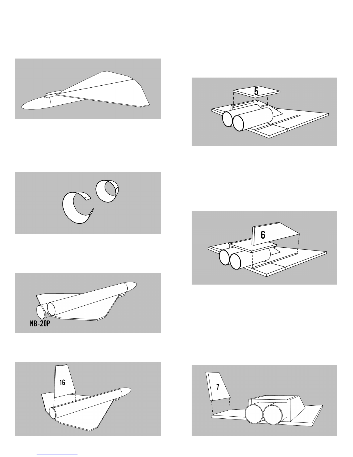
42.Cut out the nozzle shroud from the pat-
tern sheet. Form it into a cone and apply a small
amount of glue to the tab on one end as denoted by
the dotted line. Attach the free end over the glue so
its end is even with the dotted line and hold in place
until the glue sets.
43.Apply a small bead of glue around the
outside edge of the paper nose block (NB-20P) and
attach it to the end of the glider body tube. Align it
carefully and wipe away any excess glue.
44.Attach the glider rudder(16) on Line N on
the top of the glider body tube. Make sure it is per-
pendicular to the body tube and allow to dry.
41.Attach the hold-down assembly to the
bottom of the glider even with the leading edge of
the wing and perpendicular to the body tube. It will
project slightly over the nose cone.
7
11. Sand the leading edge of the inboard
housing (6) round. Apply a bead of glue along the
etched line on the main wing and along the edge of
the lower housing and the edge of the scramjet en-
gine and fit the inboard housing into place. All
these parts should make a rectangular box around
the two scramjet engines. Allow to dry.
10. Test the scramjet lower housing (5) for fit
against the scramjet engines and the housing parts.
Apply glue to the tops of the scramjet engines and
the outboard housing and the intake vane and fit
the lower housing in place. The back edge should
be even with the trailing edge of the main fin.
12.Round the leading and trailing edges of
the wingtip (7). Glue the wingtip even with the tip
edge of the main wing on the same side as the
scramjet engine housing. Make sure it is perpen-
dicular and even with the edge. Allow the assembly
to completely dry. Repeat this assembly with the
second set of parts for the other main wing assem-
bly and allow it to dry while assembling the engine
mount.
8
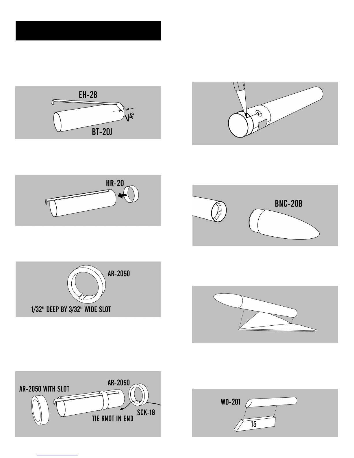
13.Using a hobby knife, punch a small 1/8”
wide slit on the engine tube (BT-20J) 1/4” from one
end. The BT-20J is 2-3/4” long. Insert one end of the
engine hook (EH-28) in the slit.
14.Slide the Retaining Ring (HR-20) over the
front of the engine tube and position it about 3/4”
from the punched end of the engine tube.
ENGINE MOUNT ASSEMBLY
15.Cut a notch 1/32” deep and 3/32” wide on
the inside of one of the centering rings (AR-2050).
This will allow the ring to clear the engine hook.
16.Tie a knot in one end of the Kevlar®
thread and pass it through the uncut centering ring.
Slide the ring onto the top of the engine tube until it
is even with the end of the tube. Slide the slotted
centering ring with the slot over the engine hook
until it is 3/4” from the bottom of the engine tube.
17
38.Check the glider nose cone (BNC-20B) for
fit, sanding if necessary. Apply a bead of glue inside
one end of the glider body tube and insert the nose
cone.
37.Cut out the Glider Marking Guide from
the pattern sheet. Wrap it around the glider body
tube about 1/4” from one end. Hold it in place with
a small piece of tape. Place a mark at both arrows
and write the corresponding letter near each mark.
Extend a line from each mark as you did with the
main body tube.
39.Apply a bead of glue along the glider
wing assembly joint. Attach the glider body tube
with the end of the tube even with the trailing edge
of the glider wings.
40.Sand one end of the thick dowel (WD-
201) so it has the same angle as the leading edge of
the glider hold-down support (15). Glue the dowel
so the front edges are aligned. Allow to dry.
16
GLIDER ASSEMBLY
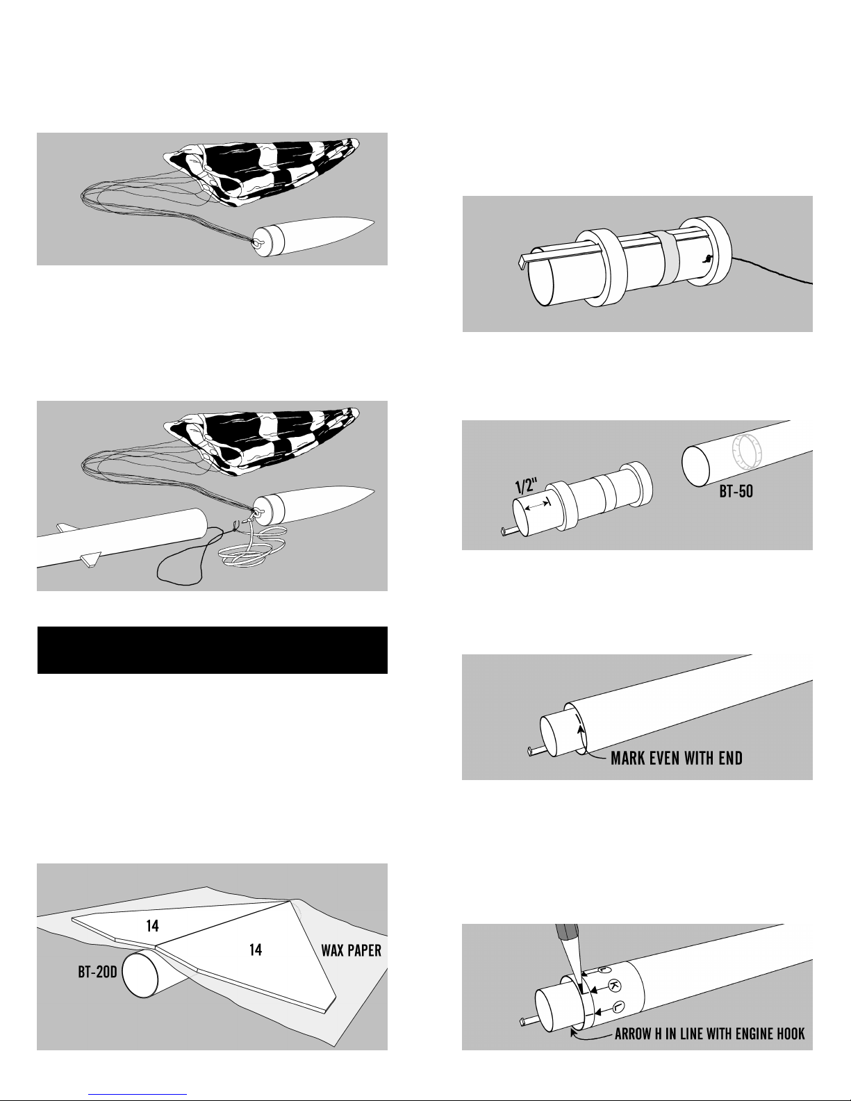
36.Lay the glider body tube (BT-20D) on a
flat surface. Place a sheet of wax paper over it to
prevent the glue from sticking while the fins dry.
Place a bead of glue on the root edge of one of the
glider wings (14) and attach it to the other wing. As
the joint starts to set, drape the assembly over the
body tube and wax paper and support the ends
while it dries.
34. Assemble chute using instructions
printed on the canopy. Attach the chute to the
screw eye.
35.Pull the Kevlar® thread out of the top of
the main body tube. Tie the loose end to one end of
the elastic cord. Tie the other end of the elastic cord
to the screw eye. Put a drop of glue on both knots
to keep them from untying.
9
19.Insert the top of the engine mount into
the BT-50 and slide it forward until the mark is even
with the end of the BT-50. Do not stop or the mount
will “freeze” in the wrong place.
18.Mark the engine mount 1/2” from the bot-
tom end. Apply a bead of glue inside one end of the
largest body tube (BT-50) about 1” from the end.
20.Cut out the Booster Marking Guide from
the pattern sheet. Wrap it around the body tube
about 1/4” from the end nearest the engine mount.
Align it so Arrow H points to the engine hook. Hold
it in place with a small piece of tape. Place a mark at
each arrow and write the corresponding letter near
each mark for future reference.
17.When all the rings are in place and the
knot is pulled up against the top ring, apply a fillet
of glue around all the joints, being careful to keep
the outside surfaces of both rings free of glue. Ap-
ply a bead of glue along the engine hook between
the two rings. Allow to dry. Store the Kevlar®
thread inside the engine tube until needed later.
10
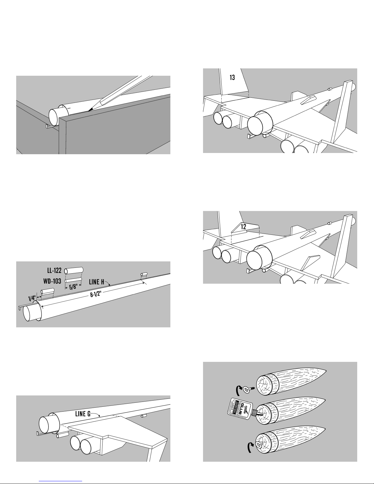
22.On line H (which is in line with the engine
hook) place a mark 8-1/2” from the end and another
mark 1/4” from the end. Cut two pieces from the
launch lug (LL-122) and two pieces of the thin wood
dowel (WD-103) to 5/8” each. Apply a bead of glue
along one side of one of the launch lug pieces and
glue one of the dowels in line with the launch lug.
Repeat for the other assembly. When they are both
dry, glue one assembly along Line H, with the
dowel towards the tube and even with the 1/4”
mark and one even with the 8-1/2” mark. Sight
down the tube to make sure they are aligned with
each other.
23.Attach one of the wing assemblies to
Line G with the scramjet housing toward the engine
hook as shown and even with the end of the body
tube. Before the glue completely sets, attach the
other wing assembly along the opposite Line G.
Support the body tube vertically while the glue
dries, checking for alignment.
21.Using a door facing, drawer, or piece of
angle molding, draw a line from each mark. Lines J,
K, and L need to be 9” from the engine end and
lines G and H need to be drawn for the entire
length. Make sure the lines are parallel to the body
tube.
15
32.Apply glue to the root edge of one of the
wing fences (12) and attach it to the line corre-
sponding to 12 drawn on the top of the wing and
even with the trailing edge. Note the orientation. It
should be perpendicular to the main wing. Repeat
with the other wing fence.
31. Apply glue to the root edge of one of the
rudders (13) and attach it to the line corresponding
to 13 drawn on the top of the wing even with the
trailing edge. It should be perpendicular to the main
wing. Repeat with the other rudder.
33. Insert the large nose cone (BNC-50Y) in
the main body tube and check for proper fit. The
nose cone should be snug to hold itself in align-
ment. If it is too loose, add masking tape. If it is too
tight, sand the shoulder slightly. Twist the screw
eye into the center of the base of the nose cone.
Unscrew it and squirt glue into the hole. Reinstall
the screw eye and wipe off any excess glue.

14
28. Apply glue to the root edge of one of the
ventral fins (10) and attach it to Line J and even
with the end of the main body tube. It should be
perpendicular to the body tube. Repeat with the
other ventral fin.
29. Apply glue to the root edge of one of the
glider supports (11) and attach it to Line L and 2-
7/8” from the bottom end of the main body tube. It
should be perpendicular to the body tube. Repeat
with the other glider support.
30. Using the Booster Alignment Template,
place a mark at the four arrows labeled 12 and 13
on the leading and trailing edge of each of the main
fins. Using a ruler, connect the lines to use as at-
tachment guides.
11
24.While the glue is setting on the wings, cut
out the Booster Wing Alignment Template from the
pattern sheet. Use it as a guide to check for proper
wing alignment.
26. Mark the booster body tube 4-1/2” from
the top on Line G on both sides. Attach the canards
on Line G with the top edge on the mark. Repeat for
the other canard.
25.Attach one of the wing fairings (8) to the
leading edge of one of the wing assemblies and
aligned on Line G. Round the leading edge of the
main wing and fairing. Repeat with the other wing
fairing.
27. Cut a piece of the launch lug (LL-122) to
1/2” long. Attach it to the top of the main body tube
9” from the top end along Line K. This launch lug
does not need the wood dowel.

12
Parts List
A 1 Body Tube........................... BT-50
B 1 Body Tube........................... BT-20D
C 1 Body Tube........................... BT-20J
D 4 Body Tubes ......................... BT-5T
E 1 Balsa Nose Cone................. BNC-50Y
F 1 Balsa Nose Cone................. BNC-20B
G 2 Adapter Rings .................... AR-2050
H 1 Paper Nose Block............... NB-20P
I 1 Retaining Ring.................... HR-20
J 1 Wood Dowel ....................... WD-201
K 1 Wood Dowel ...................... WD-103
L 1 Screw Eye............................ SE-2
M 1 Elastic Cord ........................ EC-124
N 1 Kevlar Cord ........................ SCK-18
O 1 Launch Lug ......................... LL-122
P 1 Engine Hook ....................... EH-28
Q 1 Chute Pak............................ CP-12RW
R 1 Laser cut Fins (1-17) ......... FV-66
S 1 Decal (not shown)................ DKV-66
T 1 Pattern Sheet (not shown) .. IKV-66P
13
EXPLODED VIEW
Table of contents
Other SEMROC Toy manuals


