manuals.online logo
Brands
  1. Home
  2. •
  3. Brands
  4. •
  5. ROBBE
  6. •
  7. Toy
  8. •
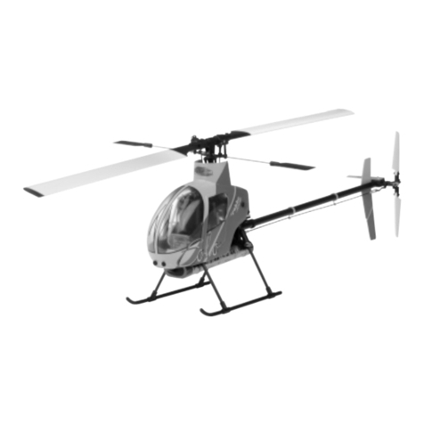
  9. ROBBE Curtiss Jenny JN-4 User manual

ROBBE Curtiss Jenny JN-4 User manual

Bau- und Betriebsanleitung
Assembly and Operating instructions
Notice de montage et d´utilisation
Curtiss Jenny
JN-4
No. 3177
Bauanleitung, Assembly instructions, Notice de montage
Curtiss Jenny JN-4
2
Technische Daten
Spannweite oben: ca. 955 mm
Spannweite unten: ca. 750 mm
Gesamtlänge: ca. 640 mm
Gesamtflächeninhalt: ca. 22 dm2
Fluggewicht: ab 520 g
Gesamtflächenbelastung: ab 23,6 g/dm2
Nicht enthaltenes, jedoch erforderliches Zubehör siehe
Beilageblatt
Werkzeuge und Hilfsmittel siehe robbe Hauptkatalog
Allgemeine Hinweise für den Bauablauf
Verschaffen Sie sich in Verbindung mit den Abbildungen
und den dazugehörigen Kurztexten einen Überblick über
die jeweiligen Bauschritte.
Verklebungen sind nur an wenigen Stellen erforderlich.
Dazu Sekundenkleber robbe Speed Typ 2 und zugehöri-
gen Aktivator verwenden.
Richtungsangaben wie z. B. „rechts“ sind in
Flugrichtung zu sehen.
Hinweise zur Fernsteueranlage
Als Fernsteuerung benötigen Sie eine Anlage ab 4
Kanälen und 4 Servos sowie einen elektronischen Regler
mit BEC - Funktion.
Es sollte ein Computer-Sender zur Verfügung stehen, da
die Ruderwege senderseitig eingestellt werden. Zudem
ist das Mischen von Querrudern und Seitenruder von
Vorteil.
Orientieren Sie sich vor Baubeginn über die
Einbaumöglichkeit der zu verwendenden Fernsteuerung.
Specification
Top wingspan: approx. 955 mm
Bottom wingspan: approx. 750 mm
Total length: approx. 640 mm
Total surface area: approx. 22 dm
2
All-up weight: min. 520 g
Surface loading: min. 23.6 g/dm
2
Please see separate sheet for details of essential items
not included in the kit.
The Robbe main catalogue includes information on a
wide range of tools and aids to building.
Sequence of assembly
Please study the instructions and the illustrations before
you start building, so that you have a clear idea before-
hand of how the model goes together.
Glued joints are only required at a few points. Use robbe
Speed Type 2 (cyano-acrylate) glue and the matching
activator for these joints.
Be sure to observe the guidelines provided by the manu-
facturers of the various adhesives you use.
Allow all glued joints to harden fully before continuing with
construction.
Directions such as „right-hand“ are as seen from the tail
of the model looking forward.
Radio control equipment
For this model you will need a 4-channnel RC system with
4 servos, plus an electronic speed controller with BEC
function.
It is really essential to use a computer transmitter, as the con-
trol surface travels can only be adjusted by modifying the
Caractéristiques techniques
Envergure de l’aile du haut: approx. 955 mm
Envergure de l’aile du bas: approx. 750 mm
Longueur totale: approx: 640 mm
Surface alaire totale: approx. 22 dm
2
Poids en ordre de vol: à partir de 520 g
Charge alaire à partir de 23,6 g/dm
2
Accessoires non contenus dans la boîte de construc-
tion mais indispensables à la construction ou à la mise
en œuvre du modèle, cf. feuillet joint
Outillage et accessoires de montage, cf. catalogue
général robbe
Consignes générales concernant le montage
Lire attentivement la notice de construction afin de se
faire une vue d’ensemble du montage et de ses diverses
étapes.
Des collages ne s’imposent qu’à très peu d’endroits. Pour
ce faire toutefois utiliser la colle cyanoacrylate robbe
Speed de type 2 et l’activateur approprié.
Tenir compte des prescriptions de fabricants des divers-
es colles recommandées.
Bien laisser durcir les points de collage.
Les données directionnelles comme gauche et droite se
rapportent au sens du vol.
Recommandations concernant la radiocommande
Pour piloter l’appareil, il suffit d’un ensemble de radio-
commande pourvu de quatre voies avec 4 servos et d’un
variateur de vitesse électronique muni de la fonction BEC.
Il est recommandé de disposer d’un ensemble de radio-
commande informatique car les débattements des gou-
vernes sont établis côté servos. Tout au moins le mixage
No.
3177
Bauanleitung, Assembly instructions, Notice de montage
Curtiss Jenny JN-4
3
Sollte eine andere, als die von uns vorgeschlagene
Steuerung verwendet werden, können Sie sich nach dem
Einbauschema richten. Maßdifferenzen sind von Ihnen
selbst auszugleichen.
Die Servos vor dem Einbau mit der Fernsteuerung in
Neutralstellung bringen (Knüppel und Trimmhebel am
Sender in Mittelstellung). Eventuell montierte
Steuerscheiben oder Servohebel entfernen.
Zur Inbetriebnahme immer den Gasknüppel in Stellung
„Motor aus“ bringen, den Sender einschalten. Erst dann
den Akku anschließen.
Zum Ausschalten immer die Verbindung Akku -
Motorregler trennen, erst dann den Sender ausschalten.
Hinweise zur Bespannung
Temparaturschwankungen während des Transports kön-
nen zu partiellem Verlust der Spannung der Bespannfolie
führen.
Die Folie spannt sich wieder, wenn mit einem Föhn
Wärme zugeführt und die Folie glattgestrichen wird.
servo travels. It is also helpful to set up an aileron - rudder
mixer.
Before you start building the model please check that
your receiving system will fit in the model as shown.
If you are using components other than the ones we rec-
ommend you can still follow the basic arrangement
shown, but you may need to make allowance for minor
differences in component size.
Before you install the servos set them all to neutral from
the transmitter - sticks and trim levers central.
Remove the servo output arms or discs.
When switching on the system always keep to this
sequence: set the throttle stick to the “motor stopped”
position, then switch the transmitter on. Only then
connect the flight battery in the model.
To switch off: always disconnect the battery from the
speed controller first, and only then switch the transmitter
off.
Notes regarding covering
Tempereture variations in transport may result in the cov-
ering film losing some of its tautness.
The film will tightn up again if you warm it with a heat gun
and smooth it down.
des ailerons et de la direction constitue un avantage pour
le pilotage.
Avant d’entreprendre la construction du modèle, il faut
être en possession de l’ensemble de radiocommande.
Si vous installez un autre ensemble de radiocommande
que celui que nous suggérons, rectifiez par vous-mêmes
les nuances de cotes.
Avant de les mettre en place, amener les servos au neu-
tre à l’aide de l’ensemble de radiocommande (manche et
trim correspondants en position médiane).
Retirer le palonnier circulaire ou le palonnier éventuelle-
ment monté sur le servo.
Pour la mise en service disposer systématiquement le
manche des gaz en position „Moteur arrêt“, mettre l'é-
metteur en marche. Raccorder d'abord l'accu.
Pour couper l'ensemble de radiocommande désolidariser
d'abord la connexion entre l'accu et le moteur, en suite
coupe l'émetteur.
Attention: des variations de témperature au cours du
transport sont susceptibles de provoquer une perte par-
tielle de tension du film de l'entoilage.
L'entoilage se retendra si vous le chauffex avec un sèche-
cheveux et le lissez.
No.
3177
No.
3177
Bauanleitung, Assembly instructions, Notice de montage
Curtiss Jenny JN-4
4
12
34
“HR”
“SR”
“H”
“S”
“S”
Bauanleitung, Assembly instructions, Notice de montage
Curtiss Jenny JN-4
5
Bild 1
- Lieferumfang
- Hinweis: Die Tragflächeneinheit vorsichtig aufklappen,
um die Verspannung nicht zu beschädigen.
Bild 2
- Seitenruderservo “SR” und Höhenruderservo “HR” mit
Servohebeln versehen.
-Am Höhenruderservo ein Servo-Verlängerungskabel
anschließen.
Bilder 3 und 4
- Servos verschrauben.
- Die Steuerseile am Rumpfende lösen und zuordnen -
siehe auch Bild 9.
- Seitenruder: Die Steuerseile treten oben am Rumpf aus.
Die entsprechenden Clipse “S” im Servo “SR” einhän-
gen.
-Höhenruder: Die zwei Clipse “H” im Höhenruderservo
“HR” einhängen.
Fig. 1
- Kit contents
- Note: unfold the wing assembly very carefully, to avoid
damaging the rigging.
Fig. 2
- Fit the output arms on the rudder servo “SR” and the
elevator servo “HR”.
- Connect an extension lead to the elevator servo.
Figs. 3 and 4
- Screw the servos in place.
-Loosen the control cables at the tail end of the fusela-
ge and assign them correctly - see also Fig. 9.
- Rudder: the control cables exit the top of the fuselage.
Connect the clips “S” to the rudder servo “SR”.
- Elevator: connect the two clips “H” to the elevator servo
“HR”.
Fig. 1
- Contenu de la livraison
- A noter : déployer avec précaution l’unité constituant
l’aile afin de ne pas en abîmer l’entoilage.
Fig. 2
- Munir le servo de la gouverne direction“SR” et le servo
de la gouverne de profondeur “HR” d’un palonnier de
servo.
- Raccorder un cordon-rallonge de servo au servo de la
gouverne de profondeur.
Fig. 3 et 4
- Visser les servos.
-Défaire les câbles de commande à la queue du fuselage
et les agencer – Cf. également fig. 9.
- Gouverne de direction : Les câbles de commande sor-
tent du fuselage par le haut.
Accrocher les clips “S” appropriés au servo “SR”.
-Gouverne de profondeur : Accrocher les deux clips “H”
au servo de profondeur “HR”.
No.
3177
No.
3177
Bauanleitung, Assembly instructions, Notice de montage
Curtiss Jenny JN-4
5
6
6
78
M 2 x 14
M 2 x 35
7
Bilder 5 und 6
- Das Seitenleitwerk in das Höhenleitwerk stecken.
Beachten: Die angeschrägten Vorderkanten der
Höhenruder müssen sich auf der Unterseite befinden -
siehe Pfeile.
Bild 7
- Die Leitwerkseinheit auf den Rumpf setzen. Die
Befestigung erfolgt mit Schrauben M 2 x 14, M 2 x 35,
Unterlegscheiben und Muttern M 2.
Bild 8
- Prinzip der Steuerseilbefestigung: Die einzelnen Ruder
in Mittelstellung bringen und fixieren (Stecknadeln).
-Clipse in den Ruderhörnern einhängen. Steuerseile und
Clipse mit Federn miteinander verbinden. Die Federn
leicht unter Spannung setzen. Stecknadeln herauszie-
hen und Neutralstellung der Ruder nochmals prüfen.
Falls erforderlich korrigieren.
- Die Knoten der Steuerseile mit einem Tropfen
Sekundenkleber sichern. Beim Kleben einen Streifen
Pappe unterlegen, um die Bespannung nicht zu
beschädigen.
Figs. 5 and 6
- Insert the fin through the slots in the tailplane.
Note: the bevelled front face of the elevators must be
on the underside - see arrows in Fig. 6.
Fig. 7
- Place the tail assembly on the fuselage. Fit the M2 x 14
and M2 x 35 screws, washers and M2 nuts to secure
the assembly.
Fig. 8
- Principle of control cable attachment: set the control
surface to centre (neutral), and pin it in place.
- Connect the clips to the horns, then connect the clips
to the cables using the coil springs supplied. Place the
springs under light tension. Pull out the pins, and check
the neutral setting of the control surfaces once more.
Correct if necessary.
-Apply a drop of cyano to the knots in the control cables.
Place a strip of card under the knot before applying the
glue, to avoid damaging the covering film.
Fig. 5 et 6
- Planter la dérive dans le stabilisateur.
Attention: Les arêtes avant biseautées des gouvernes
de profondeur doivent se trouver sur la face inférieure –
Cf. flèches.
Fig. 7
- Installer l'unité d’empennage sur le fuselage. La fixation
intervient avec les vis M 2 x 14, M 2 x 35, les rondelles
et les écrous M 2.
Fig. 8
- Principe de fixation des câbles de commande :
Amener chacune des gouvernes en position médiane et
les y fixer (avec des épingles).
- Accrocher les clips dans les guignols. Raccorder les
câbles de commande ensemble à l’aide de ressorts.
Mettre les ressorts légèrement sous tension. Retirer les
épingles et revérifier la position neutre des gouvernes.
Si nécessaire, apporter les corrections nécessaire.
-Fixer les nœuds des câbles de commande avec une
goutte de colle cyanoacrylate. Pour effectuer le collage
disposer une bande de carton en dessous afin de ne
pas abîmer l’entoilage.
Bauanleitung, Assembly instructions, Notice de montage
Curtiss Jenny JN-4 No.
3177
No.
3177
Bauanleitung, Assembly instructions, Notice de montage
Curtiss Jenny JN-4
9
8
11
10
12
9
Bilder 9 und 10
- Nach dem bei Bild 8 beschriebenen Prinzip die
Steuerseile an den Rudern anschließen.
Bild 11
- Die Querruderservos mit Servohebeln versehen; Hebel
spiegelbildlich aufstecken.
Bild 12
-Die Schachtabdeckungen für die Querruderservos vor
dem Abnehmen kennzeichnen, um sie beim späteren
Einbau nicht zu vertauschen.
- Ein Querruderservo auf der Schachtabdeckung montie-
ren. Hinweis: Je nach Servogröße kann es erforderlich
sein, passend zugeschnittene Holzklötzchen aufzukle-
ben, bevor das Servo verschraubt wird.
Figs. 9 and 10
- Connect the control cables to all the control surfaces
using the principle described in Fig. 8.
Fig. 11
- Fit output arms on the aileron servos as shown: they
should form a mirror-image pair.
Fig. 12
-Mark the servo well covers before removing them from
the wings, to avoid mixing them up later.
- Mount one aileron servo on the well cover as shown.
Note: it may be necessary to fit small wooden spacer
blocks before installing the servo, depending on the
size of the servo you are using.
Fig. 9 et 10
- Raccorder les câbles de commande aux gouvernes
selon le principe décrit par la fig. 8.
Fig. 11
- Munir les servos d’aileron de palonniers de servo ;
planter les palonniers de manière parfaitement
symétrique.
Fig. 12
- Repérer les recouvrements des logements des servos
d’aileron avant de les retirer afin de ne pas les confon-
dre par la suite lors de leur remise en place.
- Monter un servo d’aileron sur le recouvrement de loge-
ment de servo.
A noter : En fonction de la taille des servos, il peut
s’avérer nécessaire de coller les cales de bois
découpées de manière appropriée avant de visser le
servo.
Curtiss Jenny JN-4 No.
3177
Bauanleitung, Assembly instructions, Notice de montage
No.
3177
Bauanleitung, Assembly instructions, Notice de montage
Curtiss Jenny JN-4
10
13 14
15 16
Ø 2 x 6
11
Bauanleitung, Assembly instructions, Notice de montage
Curtiss Jenny JN-4
Bild 13
- Das zweite Servo entsprechend befestigen.
Bild 14
- Beide Servos mit Servoverlängerungskabeln versehen.
Bild 15
-Das Verlängerungskabel am eingezogenen Faden ver-
knoten und nach innen durchziehen.
Schachtabdeckung einsetzen. Zweites Servo einset-
zen.
Bild 16
- Prüfen, dass die Servos nicht vertauscht sind: Der
Servohebel muss zur Bohrung im Querruder fluchten.
- Abdeckungen mit Schrauben Ø 2 x 6 befestigen.
Fig. 13
- Repeat the procedure with the second aileron servo.
Fig. 14
- Connect extension leads to both aileron servos.
Fig. 15
- Tie the end of the extension lead to the thread (inside
the wing), and use it to draw the cable through to the
centre of the wing. Fit the servo well cover in the recess
in the wing. Install the second aileron servo in the same
way.
Fig. 16
- Check that you have not mixed up the servos: the out-
put arm must be in line with the horn hole in the aileron.
- Fix the servo well covers in place using 2 Ø x 6 mm scr-
ews.
Fig. 13
- Fixer le second servo en conséquence.
Fig. 14
- Munir les deux servos des cordons-rallonges de servo.
Fig. 15
- Nouer le cordon-rallonge à un fil passé dans le conduit
et le tirer vers l’intérieur.
Mettre le recouvrement de logement de servo en place.
Mettre le second servo en place.
Fig. 16
- Vérifier que les servos n’ont pas été intervertis : le
palonnier du servo doit se trouver parfaitement en ligne
avec l’alésage dans l’aileron.
- Fixer les recouvrements à l'aide de vis Ø 2 x 6.
No.
3177
17 18
19
12
Bauanleitung, Assembly instructions, Notice de montage
Curtiss Jenny JN-4 No.
3177
20
Bauanleitung, Assembly instructions, Notice de montage
Curtiss Jenny JN-4
13
Bild 17
- Ruderhörner auf der Unterseite der Querruder verkle-
ben.
Bild 18
- Querrudergestänge einhängen. Querruder in
Neutralstellung fixieren und genaue Gestängelänge
markieren.
Bild 19
-Den Sicherungsclips auf das Gestänge schieben, erst
dann das Gestänge nach Markierung abwinkeln.
Bild 20
- Gestänge im Servo und Ruderhorn einhängen.
Fig. 17
- Glue the horns in the holes in the underside of the
ailerons.
Fig. 18
- Connect the aileron pushrods to the aileron servo out-
put arms. Pin the ailerons in the neutral position and
mark the exact length of the pushrods.
Fig. 19
-Slip the keepers (retaining clips) onto the pushrods,
then bend the rods at right-angles at the marked points.
Fig. 20
- Connect the pushrods to the aileron servos and the
aileron horns.
Fig. 17
- Coller les guignols sur l’intrados des ailerons.
Fig. 18
- Accrocher la timonerie des ailerons. Fixer les ailerons
en position neutre et marquer avec précision la
longueur de la timonerie.
Fig. 19
-Glisser le clips de fixation sur la timonerie et ensuite
seulement couder la tringle en fonction du repère
appliqué.
Fig. 20
- Accrocher la tringle au servo et au guignol.
No.
3177
21 22
23 24
14
Bauanleitung, Assembly instructions, Notice de montage
Curtiss Jenny JN-4 No.
3177
M 3 x 6
Bauanleitung, Assembly instructions, Notice de montage
Curtiss Jenny JN-4
15
Bild 21
- Bei den folgenden Arbeiten die Anleitungen beachten,
die den Geräten beiliegen.
- An den Kabeln von Motor, Regler und Akku die ent-
sprechenden Steckverbindungen anlöten und mit
Schrumpfschlauch isolieren.
Bild 22
- Den Luftschraubenmitnehmer am Motor verschrauben.
Bilder 23 und 24
- Motor an den Motorträger setzen und so drehen, dass
die Bohrungen in Motor und Träger deckungsgleich
sind.
- Motor mit den Schrauben M 3 x 6 verschrauben.
Fig. 21
- Be sure to read the instructions supplied with the elec-
tronic units before carrying out the next stage.
- Solder the appropriate connectors to the wires atta-
ched to the motor, speed controller and battery, and
insulate each joint with a small piece of heat-shrink
sleeve.
Fig. 22
- Screw the propeller driver to the motor.
Figs. 23 and 24
- Place the motor against the motor mount and rotate it
until the holes in the mount line up with those in the
motor flange.
- Fix the motor to the motor mount using the M3 x 6 mm
screws supplied.
Fig. 21
- Pour les travaux suivants, tenir compte des indications
fournies par les notices jointes aux appareils.
- Souder les connecteurs appropriés aux cordons du
moteur, du variateur et de l’accu et les isoler avec des
morceaux de gaine thermorétractable.
Fig. 22
- Visser l’entraîneur d’hélice au moteur.
Fig. 23 et 24
- Installer le moteur contre le support-moteur et tourner
de telle manière que les alésages du moteur et ceux du
support coïncident parfaitement.
- Visser le moteur avec les vis M 3 x 6.
No.
3177
25 26
27 28
16
Bauanleitung, Assembly instructions, Notice de montage
Curtiss Jenny JN-4 No.
3177
Ø 2 x 6 Ø 2 x 6
Bauanleitung, Assembly instructions, Notice de montage
Curtiss Jenny JN-4
17
No.
3177
Bilder 25 bis 28
- Die fertige Antriebseinheit an den Rumpfkopf setzen
und Motorträger nach unten drücken, bis er im
Kopfspant einrastet.
- Motorträger unten und oben mit den Schrauben Ø 2 x
6 befestigen.
- Am Regler ein Servo-Verlängerungskabel anschließen.
- Der angeschlossene Regler wird durch die Öffnung
über dem Motorträger nach innen in den Rumpf
geführt. Die Akkukabel und das Anschlußkabel für den
Empfänger dabei mit nach innen führen.
Figs. 25 to 28
- Place the prepared motor assembly against the fusela-
ge nose and press the motor mount down until the tabs
engage in the slots in the nose bulkhead.
- Fit the 2 Ø x 6 mm screws top and bottom to secure the
motor mount.
- Connect a servo extension lead to the speed controller.
- Connect the speed controller to the motor, and slip it
into the fuselage through the opening above the motor
mount. Run the battery leads and the receiver lead into
the fuselage at the same time.
Fig. 25 à 28
- Installer l’unité d’entraînement terminée contre le nez
du fuselage et presser le support-moteur vers le bas
jusqu’à ce qu’il s’enclenche dans le couple du nez de
l’appareil.
- Fixer le support moteur en bas et en haut avec les vis
Ø 2 x 6.
- Raccorder un cordon-rallonge de servo au variateur.
- Le variateur raccordé sera passé par l’ouverture au-
dessus du support-moteur, vers l’intérieur dans le fuse-
lage. Ce faisant acheminer les cordons d’accu et le cor-
don de raccordement du récepteur vers l’intérieur.
29 30
31 32
18
Bauanleitung, Assembly instructions, Notice de montage
Curtiss Jenny JN-4 No.
3177
Ø 2 x 6
Bauanleitung, Assembly instructions, Notice de montage
Curtiss Jenny JN-4
19
Bild 29
- Die Motorhaube aufschieben und ausrichten. Sollte die
Haube am Mitnehmer schleifen, das vordere Loch
geringfügig erweitern.
Bild 30
- Haube mit Klebeband fixieren.
- Beidseitig 2 Löcher Ø 1,5 mm bohren und Haube mit
Schrauben Ø 2,2 x 6 befestigen.
Bild 31
- Innere Schrauben M 2 x 10 der Verspannung an der
oberen Tragfläche lösen. Schrauben jedoch in den
Holzzungen stecken lassen.
- Den Rumpf von hinten zwischen die Tragflächeneinheit
fädeln, bis die untere Tragfläche in der
Rumpfaussparung sitzt.
Bild 32
- Die Baldachinstreben mit den Schrauben M 2 x 10 und
Muttern M 2 an der oberen Fläche befestigen -
Schrauben noch nicht festziehen.
Fig. 29
- Fit the cowl over the nose and position it carefully. If the
cowl fouls the propeller driver, open up the front hole
slightly.
Fig. 30
- Tape the cowl to the fuselage.
- Drill two 1.5 mm Ø holes on both sides, and attach the
cowl using 2.2 Ø x 6 mm screws.
Fig. 31
- Loosen the inner M2 x 10 rigging screws of the top
wing, but leave the screws in the wooden lugs.
-Thread the fuselage through the wing assembly from
the rear until you are able to fit the bottom wing in the
wing saddle.
Fig. 32
- Attach the cabane struts to the top wing using the M2
x 10 screws and M2 nuts, but do not tighten the screws
at this point.
Fig. 29
- Mettre le capot moteur en place et l’aligner. S’il arrivait
que le capot frotte à l’entraîneur, agrandir légèrement le
trou avant.
Fig. 30
- Fixer le capot avec des morceaux de ruban adhésif.
- Bilatéralement, percer deux trous de Ø 1,5 mm et fixer
le capot avec les vis Ø 2,2 x 6.
Fig. 31
- Desserrer les vis intérieures M 2 x 10 du haubanage de
l’aile du haut. Laisser toutefois les vis plantées dans les
languettes de bois.
- Enfiler le fuselage par l’arrière entre la voilure jusqu’à ce
que l’aile du bas s’installe dans le dégagement du fuse-
lage.
Fig. 32
- Fixer les étais de baldaquin avec les vis M 2 x 10 et les
écrous M 2 à l’aile du haut – ne pas encore serrer les
vis.
No.
3177
33 34
35 36
20
Bauanleitung, Assembly instructions, Notice de montage
Curtiss Jenny JN-4 No.
3177

This manual suits for next models

1

Other ROBBE Toy manuals

ROBBE 8069 User manual

ROBBE

ROBBE 8069 User manual

ROBBE ST.Tropez User manual

ROBBE

ROBBE ST.Tropez User manual

ROBBE Amica User manual

ROBBE

ROBBE Amica User manual

ROBBE Gemini User manual

ROBBE

ROBBE Gemini User manual

ROBBE SPEEDY WING Instruction Manual

ROBBE

ROBBE SPEEDY WING Instruction Manual

ROBBE Eolo R 22 User manual

ROBBE

ROBBE Eolo R 22 User manual

ROBBE BLUE ARROW CP120 S-FHSS RTB User manual

ROBBE

ROBBE BLUE ARROW CP120 S-FHSS RTB User manual

ROBBE Corsair ARF FW004006 Operating instructions

ROBBE

ROBBE Corsair ARF FW004006 Operating instructions

ROBBE SLIDER QE 2686 Instruction Manual

ROBBE

ROBBE SLIDER QE 2686 Instruction Manual

ROBBE 26950002 User manual

ROBBE

ROBBE 26950002 User manual

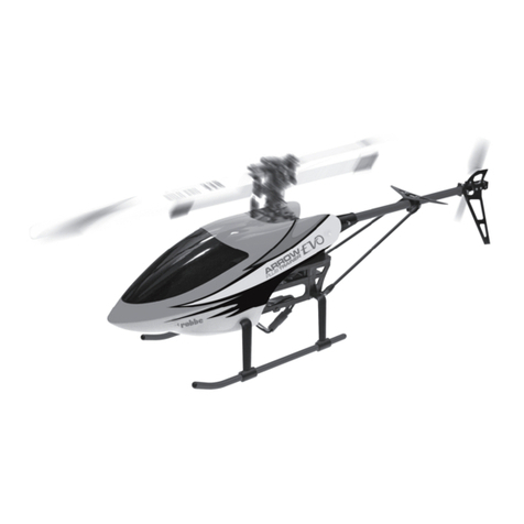
ROBBE ARROW PLUS TRAINER EVOLUTION User manual

ROBBE

ROBBE ARROW PLUS TRAINER EVOLUTION User manual

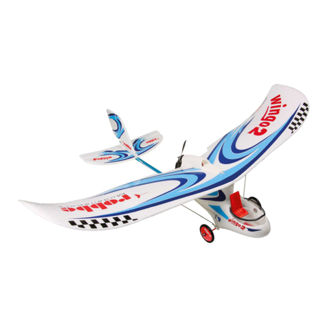
ROBBE Wingo 2 Instruction Manual

ROBBE

ROBBE Wingo 2 Instruction Manual

ROBBE Hot Shot 3078 Instruction Manual

ROBBE

ROBBE Hot Shot 3078 Instruction Manual

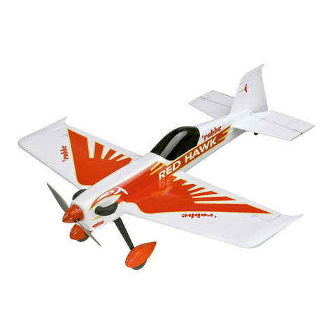
ROBBE Red Hawk KIT User manual

ROBBE

ROBBE Red Hawk KIT User manual

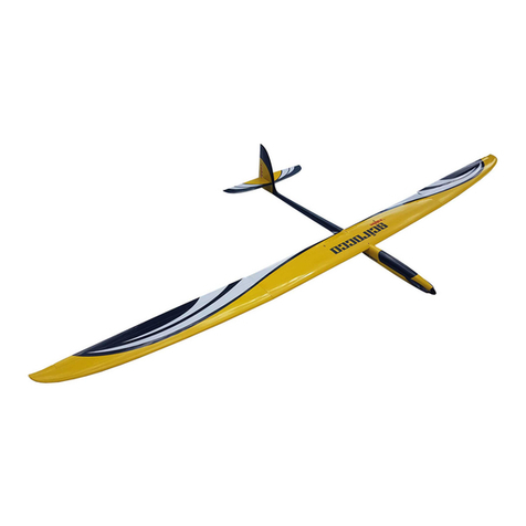
ROBBE Scirocco Instruction Manual

ROBBE

ROBBE Scirocco Instruction Manual

ROBBE Valdivia User manual

ROBBE

ROBBE Valdivia User manual

ROBBE Togo User manual

ROBBE

ROBBE Togo User manual

ROBBE MDM-1 FOX Instruction Manual

ROBBE

ROBBE MDM-1 FOX Instruction Manual

ROBBE BLUE ARROW XL 490 User manual

ROBBE

ROBBE BLUE ARROW XL 490 User manual

ROBBE AMPLITUDE Instruction Manual

ROBBE

ROBBE AMPLITUDE Instruction Manual

ROBBE CALIMA 2640 Instruction Manual

ROBBE

ROBBE CALIMA 2640 Instruction Manual

ROBBE BLUE ARROW NANO LOOP 2.4 GHz User manual

ROBBE

ROBBE BLUE ARROW NANO LOOP 2.4 GHz User manual

ROBBE Light Thing User manual

ROBBE

ROBBE Light Thing User manual

ROBBE Mistral 2.0 Instruction Manual

ROBBE

ROBBE Mistral 2.0 Instruction Manual

Popular Toy manuals by other brands

Mega Construx HALO PRO BUILDERS GFT42 instruction sheet

Mega Construx

Mega Construx HALO PRO BUILDERS GFT42 instruction sheet

Fisher-Price LITTLE PEOPLE L3940 instruction sheet

Fisher-Price

Fisher-Price LITTLE PEOPLE L3940 instruction sheet

Fisher-Price imaginext Dinosaurs J7486 manual

Fisher-Price

Fisher-Price imaginext Dinosaurs J7486 manual

Faller HALF-TIMBERED TWO-FAMILY HOUSE manual

Faller

Faller HALF-TIMBERED TWO-FAMILY HOUSE manual

Kraftei TO-0880006 user manual

Kraftei

Kraftei TO-0880006 user manual

REVELL NH90 NFH Navy Assembly manual

REVELL

REVELL NH90 NFH Navy Assembly manual

Burl Rice PS 5077 user manual

Burl Rice

Burl Rice PS 5077 user manual

Canon Creative Park Budgerigar Assembly instructions

Canon

Canon Creative Park Budgerigar Assembly instructions

Avios Albatross instruction manual

Avios

Avios Albatross instruction manual

Hasbro Martian Matter Alien Lab manual

Hasbro

Hasbro Martian Matter Alien Lab manual

Fisher-Price M5606 instruction sheet

Fisher-Price

Fisher-Price M5606 instruction sheet

Fisher-Price Musical Scoop Coupe manual

Fisher-Price

Fisher-Price Musical Scoop Coupe manual

REVELL B-25 Bomber Assembly manual

REVELL

REVELL B-25 Bomber Assembly manual

Hacker A30-UAV manual

Hacker

Hacker A30-UAV manual

Fischer-Price WILD THINGS Series instruction sheet

Fischer-Price

Fischer-Price WILD THINGS Series instruction sheet

Hasbro DISNEY STAR WARS OBI-WAN KENOBI FORCE FX... manual

Hasbro

Hasbro DISNEY STAR WARS OBI-WAN KENOBI FORCE FX... manual

st model Arcus M product manual

st model

st model Arcus M product manual

Hasbro NERF PRO GELFIRE X MR BEAST quick start guide

Hasbro

Hasbro NERF PRO GELFIRE X MR BEAST quick start guide

manuals.online logo
manuals.online logoBrands
  • About & Mission
  • Contact us
  • Privacy Policy
  • Terms and Conditions

Copyright 2025 Manuals.Online. All Rights Reserved.