Sencon SI9500 User manual

SI9500
Digital Film Weight Gauge
User Manual
REF OPERATION
MANUAL No. 092-00600-08
LANGUAGE ENGLISH
REVISION 8

CONTENTS
1. INTRODUCTION AND MODE SELECTION ........................... 6
1.1 PURPOSE.................................................................................................................. 6
1.2 METHOD OF MEASUREMENT ................................................................................ 6
1.3 CHOOSING AN OPERATING MODE ....................................................................... 7
1.4 CHANGING THE OPERATING MODE ..................................................................... 7
2. FAMILIARISATION AND PREPARING FOR USE................. 8
2.1 VOLTAGE SELECTION............................................................................................. 8
2.2 2.2 CONNECTING PROBES..................................................................................... 9
2.3 CONNECTING A FOOTSWITCH ............................................................................ 10
2.4 IDENTIFICATION OF KEYS AND DISPLAYS ........................................................ 10
2.5 SWITCH ON AND SELF TEST................................................................................ 12
2.6 UNIT DOES NOT WORK......................................................................................... 12
2.7 MASTER RESET ..................................................................................................... 13
2.8 SELECTING DISPLAYED DECIMAL PLACES ....................................................... 13
2.9 SELECTING LINE NUMBER PROMPT................................................................... 14
2.10 SET-UP MODE ........................................................................................................ 15
2.11 ENTERING SET-UP MODE .................................................................................... 15
2.12 CHANGING THE PASSCODE ................................................................................ 15
2.13 CALIBRATING THE PROBE ................................................................................... 15
3. USING THE INSTRUMENT IN FIXED CHANNEL MODE .... 17
3.1 OVERVIEW.............................................................................................................. 17
3.2 SELECTING THE CHANNEL .................................................................................. 17
3.3 CALIBRATING THE CHANNELS ............................................................................ 17
3.4 TAKING READINGS................................................................................................ 18
3.5 READING FAULTS .................................................................................................. 18
4. USING THE INSTRUMENT IN CUSTOM CHANNEL MODE 19
4.1 OVERVIEW.............................................................................................................. 19
4.2 SETTING UP A LACQUER TYPE ........................................................................... 19
4.3 CHANGING A SET-UP VALUE ............................................................................... 20
4.4 ERASING A SET-UP VALUE .................................................................................. 20
4.5 CALIBRATING A LACQUER TYPE......................................................................... 20
4.6 FREQUENCY OF CALIBRATION ........................................................................... 21
4.7 TAKING READINGS................................................................................................ 21
4.8 READING FAULTS .................................................................................................. 21
4.9 CUSTOM CHANNEL SET-UP/SUMMARY ............................................................. 22
4.10 CUSTOM CHANNEL SET-UP/SUMMARY ............................................................. 23
4.10.1 MULTI-POINT CALIBRATION .................................................................................23
5. ACCURACY AND LINEARITY ............................................. 24
5.1 INSTRUMENT TESTS AND CHECKS .................................................................... 24
5.2 FACTORS AFFECTING ACCURACY ..................................................................... 24
6. USING THE SI9500 WITH A PRINTER ................................ 25
6.1 OVERVIEW.............................................................................................................. 25
6.2 CHOOSING A PRINTER ......................................................................................... 25
6.3 CONNECTING THE PRINTER................................................................................ 26
6.3.1 THE EPSON FX OR EX PRINTER.............................................................................26
6.3.2 THE TANDY DMP132 PRINTER ...............................................................................27
6.3.3 USING OTHER PRINTERS ........................................................................................27

6.4 SETTING UP THE RS232 DATA FORMAT .............................................................27
6.4.1 SETTING UP THE EPSON PRINTER ....................................................................... 28
6.4.2 SETTING UP THE TANDY PRINTER ...................................................................... 29
6.4.3 SETTING UP OTHER PRINTERS ............................................................................. 29
6.5 ENABLING THE PRINTOUT....................................................................................29
6.6 SELECTING THE PRINTOUT FORMAT .................................................................30
6.7 PRINTER PROBLEMS .............................................................................................31
7. USING THE SI9500 WITH A COMPUTER............................ 32
7.1 GENERAL.................................................................................................................32
7.2 COMPUTER PORT CONNECTIONS ......................................................................32
7.3 SETUP COMPUTER PORT .....................................................................................33
7.4 SETTING DATA FORMAT AND SPEED .................................................................35
7.5 UNI-DIRECTIONAL PROTOCOL.............................................................................35
7.6 BI-DIRECTIONAL PROTOCOL................................................................................35
7.7 FORMAT OF MESSAGE TRANSMITTED ...............................................................36
7.8 ERROR MESSAGES................................................................................................37
8. APPENDIX 1......................................................................... 38
9. APPENDIX 2......................................................................... 42
10.SI9507 FINISHED CAN PROBE........................................... 43
11.ADDENDUM ......................................................................... 44
11.1 MULTI-POINT CALIBRATION..................................................................................44
11.1.1 Introduction .................................................................................................................. 44
11.1.2 Setting for Multi-Point Calibration .............................................................................. 44
11.1.3 Operation...................................................................................................................... 44

A. PREFACE
The SI9500 is a professional instrument that if used correctly will give
accurate results and service. It is essential that users familiarise themselves
with its operation and that before being put into use the instrument is set up
correctly.
The person responsible for the instrument should read this manual,
particularly Chapter 2 and then either Chapter 3 or Chapter 4 depending
upon the chosen operating mode. When this has been done the following
quick guide may be used as a reminder of the sequence of operations.
ON THE FRONT COVER:
Top picture
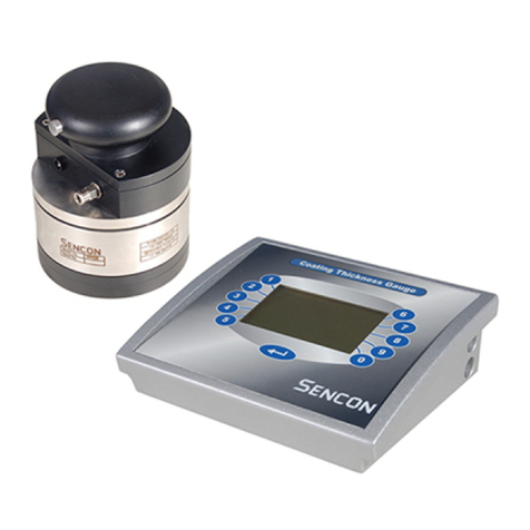
SI9500 Film Weight Gauge.
Bottom picture
Left view - SI9505 Flat sheet probe.
Top middle view - SI9507 Formed can probe.
Right view - SI9550 Hover Probe.

B. QUICK GUIDE
1. TO CALIBRATE FLAT SHEET PROBE/FORMED CAN PROBE.
A) Attach crocodile clip to test sample but make sure probe is not
in contact.
B) Enter set-up mode by: pressing CALIBRATE and LACQUER
NUMBER together. (PASS should appear in large display, if
not press END and try set-up mode again) then enter
PASSWORD. (9963 if unchanged).
C) Press CALIBRATE. (CP will appear in the small display).
D) Press ENTER. (The large display will show 0.00)
E) Press END twice.
2. TO SET-UP A LACQUER TYPE.
A) Enter set-up mode by: pressing CALIBRATE and LACQUER
NUMBER together. (PASS should appear in the large display,
if not press END and try set-up mode again) then enter
PASSWORD. (9963 if unchanged)
B) Press LACQUER NUMBER. (?? will appear in the small
display).
C) Enter new lacquer number by using NUMBER KEYS.
D) Press ENTER. (???? will appear on large display).
E) Enter set piece value: by using NUMBER KEYS.
F) Press ENTER.
G) Press END.
3. TO CALIBRATE A LACQUER TYPE.
A) Press CALIBRATE.
B) Press LACQUER NUMBER. (?? will appear in the small
display).
C) Enter new lacquer number by using NUMBER KEYS.
D) Press ENTER.
E) Place probe on known test sample. (remember to apply
pressure if the flat sheet probe is being used). Press ENTER
before releasing.
F) Press END.
4. TO TAKE READINGS.
A) Select appropriate lacquer number by using the UP/DOWN
ARROW KEY.
B) Place probe on sample.
C) Note readings. (Press ENTER if using printer or host
computer).

1. INTRODUCTION ND MODE SELECTION
1.1 PURPOSE
The Sencon SI9500 Digital Film Weight Gauge is an instrument designed for
use in the can, end and lid making industries. It enables the film weight of
lacquers and coating to be measured.
By incorporating a microprocessor and advanced electronic techniques into
the instrument it has been made capable of optimum accuracy, linearity and
ease of use.
1.2 METHOD OF MEASUREMENT
The instrument establishes film weight by measuring the capacitance
between a conductive probe tip and the metallic substrate whilst separated
only by the lacquer film under test.
The capacitance will be proportional to the separation between probe and
substrate (i.e. lacquer thickness) if the probe tip dimensions and dielectric
strength of the lacquer are constant. Unfortunately different formulations of
lacquer exhibit different dielectric strengths, it is therefore necessary to use
the instrument as a comparator to establish film thickness (or weight) of an
unknown sample by comparing it to a known sample of the same lacquer
type.
It should be noted that the electrical signals applied to the probe and the
connection that attaches to the substrate are of low voltage and represent no
hazard whatsoever regardless of how they are handled.
Probe
Rubber
tip
Metal
substrate
Lacquer

CHOOSING AN OPERATING MODE
The SI9500 can be altered by the user between two operating modes. The
jumper is located inside the unit and is not intended for frequent operation. It
is therefore necessary to decide which of the two modes described below will
best suit your particular requirements.
Fixed Channel Mode In this mode the unit will automatically
create fifty channels, each with a slightly higher calibration setting than
the previous, to span the usable range of calibration settings. In use,
the user finds the channel number that gives the closest reading to the
true reading of the known sample and then uses that channel for all
subsequent readings of that lacquer type.
This is a very similar method as used by STRAND (TM) gauges and
their imitators that offered twelve channels.
Custom Channel Mode In this mode, ninety nine channels are
made available, each of which the user can calibrate exactly to a
particular lacquer type. In use the user selects the channel (lacquer
number) that has been previously set to the lacquer type that is being
measured.
It is worth noting that all settings are permanently retained in the units
memory until they are erased or re-set.
Of these two modes, custom channel mode offers the greatest accuracy but
imposes the requirement of having to undertake a set up procedure (once)
for each lacquer type used.
1.4 CHANGING THE OPERATING MODE
Unless otherwise requested, Sencon ship each gauge set to operate in
custom channel mode. If your gauge is so set and you wish to change it to
fixed channel mode it is necessary to change a switch setting inside the
gauge. Instructions for gaining access to, and identifying the switch are
given in Appendix 1.
The switch that selects the operating mode is switch 1. With the switch
closed fixed channel mode is selected, with the switch open custom channel
mode is selected. Carefully read all instructions in Appendix 1 before
attempting to change this switch.
NOTE: After changing operating mode it is necessary to perform a
master reset (see section 2.7).

2. F MILI RIS TION ND PREP RING FOR USE
2.1 VOLTAGE SELECTION
Unless otherwise instructed Sencon will ship 220-240V 50/60Hz models to all
European customers and 110-120V 50/60Hz models to all U.S.A. customers.
The operating voltage is
clearly indicated by a label on the bottom of the unit and the type of mains
lead (power cord) fitted, the 110V models having a moulded U.S.A. style
integrated mains lead and plug.
A switch is provided inside the instrument to change it between 110V and
220/240V operation, this can be identified by referring to Appendix 1.
Carefully read all instructions in Appendix 1 before changing this switch
position, and take note that the voltage label must be changed and the colour
code of the mains lead could potentially cause subsequent confusion with
resultant damage to the instrument.
220/240V models must be fitted with a mains plug appropriate for the country
of use in accordance with the following connection instruction;
BROWN WIRE - LIVE
BLUE WIRE - NEUTRAL
GREEN/YELLOW - EARTH
THIS UNIT MUST BE EARTHED
Mains Lead
ON/OFF button

If a 110V model is to be fitted with an alternative mains plug the following
colour code should be noted;
BLACK WIRE - LIVE (HOT)
WHITE WIRE - NEUTRAL
GREEN WIRE - EARTH
2.2 CONNECTING PROBES
The unit can be used with Sencon probes or other types of capacitance
probe, for example, probes designed for use with STRAND (TM) gauges.
If a Sencon probe is used it will have an integral lead that can be connected
directly to the probe socket
on the side of the instrument case. The probe lead cannot be inadvertently
fitted into any of the other sockets.
If a non Sencon probe is used it will be necessary to use a probe adapter
lead, available from Sencon. This connects into the probe socket and is
terminated with a 4mm banana plug and a crocodile clip, the plug should
connect to the probe, the clip is attached to the substrate of the item under
test.
Foot switch
2 PIN
Probe
5 PIN
Computer
PIN Printer
3 PIN
(covered in this view)

2.3 CONNECTING A FOOTSWITCH
The use of a footswitch enables readings to be captured into the instrument
memory whilst keeping both hands on the probe or test piece.
The optional Sencon footswitch is supplied complete with a lead that will
connect into the footswitch socket on the side of the instrument case.
2.4 IDENTIFICATION OF KEYS AND DISPLAYS
The various keys and displays are shown on the adjacent photo and will be
described in detail in later chapters. They are generally used as follows;
Foot switch

OPERATION
KEYS
NUMERIC
KEYPAD

Status Indicators - used to show whether the instrument is in
measure mode, calibrate mode or set-up
mode with the top indicator used to warn of a
reading fault such as damaged lacquer,
pinhole or missing lacquer.
Lacquer Number Display - used to indicate which channel number (1
to 50) is selected in fixed channel mode or
which lacquer number (1 to 99) is selected in
custom channel mode.
Film Weight Display - displays the reading or set-up value. Note,
because the unit is a comparator (see 1.2)
the Film Weight Display will always be in the
same units as the known sample.
Numeric Keypad - used to select channel/lacquer number,
line numbers and used to enter preset values
when in custom channel mode.
Operation keys - used to select between measure, calibrate
and set-up mode, change channel/lacquer
numbers, clear incorrect keystrokes and by
using the up and down keys, select a
channel or lacquer number.
2.5 SWITCH ON AND SELF TEST
The mains on/off switch on the back of the instrument case is a push on -
push off type. When the unit has been plugged in it may be switched on and
a self test routine will be initiated.
First the integrity of the battery-backed memory is checked and should an
error be detected, the main display will flash "FAIL". If this occurs a master
reset should be performed, see section 2.7. The CLEAR key can be pressed
to continue operation of the gauge, but the chance that previously saved
readings are corrupted is very high.
If the battery-backed memory passes its test the displays will cycle from 0 to
9 and all indicators will illuminate. Any faulty indicators or displays can
therefore be identified.
2.6 UNIT DOES NOT WORK

If after switching on, the self test routine does not run and no indicators or
displays illuminate then suspect a blown fuse or fault in the mains supply.
Investigations of mains or fuse faults should only be undertaken by
competent trained personnel.
First check that power is available at the mains receptacle, check that the
mains plug is fully and correctly inserted. If the mains plug is a fused type
check that fuse and if necessary replace with a 3A cartridge fuse.
If all of the above are O.K. then check the internal fuse after first removing
the mains plug completely. The internal fuse will be found inside the
instrument case on the printed circuit board adjacent to the mains lead inlet.
Only one fuse is used, which is a 250mA 250V 20mm slow blow cartridge
fuse. The second fuse carrier carries a spare fuse.
If the fuse is O.K. but the unit still will not work, or the fuse repeatedly blows
the gauge should be returned to Sencon for repair.
2.7 MASTER RESET
In the event of a major change, error or fault it may become necessary to
completely reset the instrument. This is always required when the operating
mode is changed.
A reset will erase all stored settings and readings from the units memory.
To perform a master reset proceed as follows;
A) Switch off power to the unit.
B) Simultaneously hold down the ENTER, CLEAR and
END keys.
C) Switch on the power.
D) After 2 seconds release the keys and the system will be reset.
2.8 SELECTING DISPLAYED DECIMAL PLACES
It is possible to select between one or two decimal places on the displayed
reading. The choice largely depends upon user preference, with two decimal
places greater resolution is possible but on the other hand the readings
appear to be less stable as the displayed resolution is greater than the test
accuracy. This can create a degree of confusion with operators.
The choice is made using internal switch 1 position 1 which selects one
decimal place when open, two decimal places when closed. Refer to
Appendix 1 for instructions on accessing and identifying this switch.

2.9 SELECTING LINE NUMBER PROMPT
It may be advantageous to relate printed or transmitted readings to a
particular production line number so the unit can be made to prompt the
operator for a line number for each batch of readings. A line number must
then be entered to which readings will be related until the next line number is
entered. A range of line numbers from 0 to 99 is allowed thus enabling this
facility to be used for other purposes i.e. machine number or reading position
etc.
To select the line number prompt internal switch 1 position 2 should be
closed. Refer to Appendix 1 for instructions on accessing and identifying this
switch.

2.10 SET-UP MODE
Set-up mode enables the allocation of set-piece (known sample) values of
different lacquers to the 99 channels in custom channel mode. It also
enables the probe to be exactly matched to the instrument by cancelling out
stray admittance created by the probe and its leads, this latter function is
known as calibrating the probe.
To prevent unauthorised access to the set-up values a passcode must be
keyed in before set up mode is enabled. The passcode is initially set to 9963
but may be
changed to any 4 digit number. The passcode will always be reset to 9963 if
a master reset is performed.
2.11 ENTERING SET-UP MODE
To select set-up mode the CALIBRATE and LACQUER NUMBER keys must
be pressed simultaneously. This will cause the SET-UP indicator to
illuminate and the word PASS displayed.
The four digit passcode should now be entered and if keyed in correctly the
unit will be in set-up mode. If entered incorrectly the instrument will drop
back to measure mode.
2.12 CHANGING THE PASSCODE
To change the passcode it is necessary to first enter set up mode using the
current passcode, then simultaneously press LACQUER NUMBER and
CALIBRATE again. The display will show question marks with P1 in the
lacquer number display. The new passcode is now entered (4 digits) and the
lacquer number display will change to P2. The new passcode must now be
entered again to confirm it and it will become effective.
If a different passcode is entered the second time (whilst P2 is in the lacquer
display) an error will be indicated and the passcode will not be changed.
2.13 CALIBRATING THE PROBE
It is essential to calibrate the probe if the unit is to operate over its correct
range. In calibrating the probe any capacitance associated with the probe
and its leads is cancelled out.

To calibrate the probe first ensure that it is connected correctly to the
instrument BUT NOT ON OR CONNECTED TO A SAMPLE. Then follow the
following procedure;
A) Enter Set-up mode (See 2.11).
B) Press the CALIBRATE key.
At this point the display will show the amount of offset
required and the lacquer number display will indicate CP.
C) Press the ENTER key.
The display should indicate zero.
D) Press the END key twice.
The instrument will then drop back to measure mode.
Probes should be calibrated whenever they are changed and at periodic
intervals dependant upon the type of probe, its condition and amount of use.
By monitoring the amount of offset required to re-calibrate the probe
experience will suggest the appropriate re-calibration period.

3. USING THE INSTRUMENT IN FIXED CH NNEL MODE
3.1 OVERVIEW
Fixed channel mode provides perhaps the most straight forward operation
but with a lower accuracy than custom channel mode. In this mode it is not
necessary to set up any values in the instrument other than probe calibration
as described in 2.13.
In use, a channel is chosen that gives a reading as close as possible to the
actual value of the known sample. This channel is then used to measure all
subsequent samples of that lacquer type.
All operations in fixed channel mode except probe calibration and channel
calibration take place with the MEASURE indicator illuminated.
3.2 SELECTING THE CHANNEL
To find the most suitable channel the known sample is placed in (or under)
the probe and the reading noted. (do not forget to clip the crocodile clip to
the substrate of the sample).
If the displayed reading is below the actual value of the sample press the up
arrow key to increase the channel number as indicated by the lacquer
number display until the nearest reading is found.
If the displayed reading is above the actual value of the sample press the
down arrow key until the closest reading is found.
When the closest reading has been found the channel or lacquer number as
indicated is the channel that should be used for all measurements on that
particular lacquer types.
3.3 CALIBRATING THE CHANNELS
In fixed channel mode the instrument is calibrated against a stable internal
reference. Whilst in MEASURE mode press CALIBRATE. The instrument
will automatically select the internal reference, select channel 25 (this gives
the best accuracy) and calibrate the instrument. All channels will be
calibrated simultaneously.

3.4 TAKING READINGS
Having previously ascertained the correct channel for a particular lacquer
type readings are easily taken by placing the unknown samples in or under
the probe and noting the value displayed whilst the correct channel is
selected.
Channels are selected by using the up and down keys or alternatively by
pressing the LACQUER NUMBER key and entering the channel number on
the keypad followed by the ENTER key.
3.5 READING FAULTS
If the FAULT indicator illuminates and the display reads "Poor" then a pinhole
or missing lacquer exists on the sample currently being measured.
If no channel suits the known sample or a reading is significantly different to
the expected value then check the following;
1) The probe crocodile clip is making good contact with the
metallic substrate of the sample.
2) The probe is being used correctly i.e. square to the sample with
the correct pressure applied.
3) The probe tip is clean and undamaged.
4) Probe connections are O.K. and operators hands are not in
contact with conductor of probe wire.
It should be noted that the gauge is believed capable of coping with the
complete range of lacquer types and film weights used by the can, ends and
lids industries, excepting those with high metallic content.
Whilst a valid reading is not being obtained from the sample the display will
show "void". If no reading can be obtained by placing the probe on the
sample then check items 1 to 4 above.

4. USING THE INSTRUMENT IN CUSTOM CH NNEL
MODE
4.1 OVERVIEW
Customer channel operation provides for increased accuracy but requires
that a "once off" set-up is performed for each lacquer type used. In use a
channel is calibrated exactly to the known sample of a given lacquer type.
Readings of that lacquer type are then taken when that channel or lacquer
number is selected. The instrument can be calibrated to cope with up to 99
different lacquer types.
To prepare the instrument to cope with a new lacquer it is necessary to
perform a set-up, however, as the set-up data is permanently stored, this
operation need never be repeated.
4.2 SETTING UP A LACQUER TYPE
When the gauge is first received no lacquers will be set-up in its memory and
this situation will be returned to if a master reset is performed (see 2.7). In
this state the unit is incapable of taking readings.
To enter a lacquer type first enter set-up mode as described in 2.11
(simultaneously press CALIBRATE and LACQUER NUMBER followed by
the 4 digit password). When this has been done the SET-UP indicator will
illuminate and the lacquer number display will show the last used lacquer
number, or if none are programmed, it will show lacquer number 1.
Next press the LACQUER NUMBER key, the display will indicate two
question marks and a number in the range 1 to 99 must now be chosen to
assign to the particular lacquer type that is being set-up. If you wish to see
which lacquer numbers are already in use, repeatedly press the up or down
arrow keys and the display will cycle through all lacquer numbers already
programmed.
Enter a 1 or 2 digit lacquer number followed by the ENTER key and the film
weight display will then show 4 question marks.
It is now necessary to enter the value of the known sample for that lacquer
type (1 to 4 digits including decimal point with 1 or 2 decimal places as
selected - see 2.8) followed by the ENTER key.
That channel has now been set-up, to set-up a further channel press the
LACQUER NUMBER key again or to finish setting up press the END key and
the unit will drop back to MEASURE mode.

4.3 CHANGING A SET-UP VALUE
It may be necessary to change the value associated with a particular channel
number for instance if a new known sample with a different film weight is
obtained for that lacquer.
To change a set-up value follow the procedure described in 4.2 and select
the lacquer number to be changed.
Instead of displaying 4 question marks the film weight display will indicate the
currently entered set piece value (reading of the known sample). The new
set piece value may now be entered followed by the ENTER key.
Use the END key to set-up mode.
4.4 ERASING A SET-UP VALUE
If a lacquer type goes out of use it can be erased from the unit.
To erase a lacquer number first select that lacquer number in set-up mode as
described in 4.2, then press the CLEAR key.
Use the END key to leave set-up mode.
4.5 CALIBRATING A LACQUER TYPE
Having set-up a lacquer number with its set piece value it is then necessary
to store the calibration setting for that particular lacquer type.
To enter CALIBRATION mode (from MEASURE mode) press the
CALIBRATE key, the CALIBRATE indicator will illuminate.
Then select the lacquer number to calibrate by pressing the arrow keys or by
pressing LACQUER NUMBER followed by a 1 or 2 digit number and the
ENTER key.
Carefully place the set piece (known sample) in, or under the probe and
press the ENTER key, the film weight display will change to the programmed
value for that set piece.
NOTE - If using two decimal places of accuracy it is not
unusual for the reading to continually vary and
appear unstable -see chapter 5.
To leave CALIBRATION mode press the END key.
Other manuals for SI9500
1
Table of contents
Other Sencon Measuring Instrument manuals

