Suin SA2200 User manual

User’s Guide
SA2200 Power Quality Analyzer
Suin Instruments Co.,Ltd. 07/2018

SA2200 Power Quality Analyzer User’s Guide
Suin Instruments Co.,Ltd.
-1-
Introduction
SA2200 power quality analyzer adopts DSP+ARM dual processor hardware platform and
embedded operation system (uClinux), which can calculate a large number of electrical
parameters and process all data quickly. The device offers extensive and powerful
measurements functions to check power distribution system, so it can detect quality of power
grid and electrical characteristics rapidly and conveniently. The analyzer has large-screen color
LCD display interface, and easy-to-use keyboard.
Main features:
Waveform real-time display(4 voltages/4 currents)
Half cycle RMS measurement (voltage and current)
intuitive operation
variety of optional current clamps
Measure DC component
Measurement of harmonics can be up to 100 times.
Transient capture
Vector, Trend, Bar Graph and events table display
Active power, reactive power, apparent power and energy, shift power factor and
true power factor
Three-phase unbalance (voltage and current)
Flicker
Inrush current
Detection and record of Dips& Swells, Voltage Rapid Change, Interruption.
Detect according to EN50160 or grid with user-defined limit.
data storage and screenshots (can be replayed or output to a PC)
Through the LAN interface PC can keep real-time remote communication
with the Analyzer, operate the Analyzer and download measurement data.
Built-in 32G memory card.
WIFI communication is supported.

SA2200 Power Quality Analyzer User’s Guide
Suin Instruments Co.,Ltd. -2-
The Analyzer and its accessories
SA2200 Power Quality Analyzer 1
CD (PC software + manual) 1
Voltage Test Leads 5
Alligator Clips 5
Power adapter 1
Power cord 1
Soft Carry Bag 1
Hang strap 1
Options
AC Current Transformer
KLC8C-5A (5A)
CTC0080 (50A)
CTC0130 (100A)
CTC1535 (1000A)
AC Rogowski Coil
SY-1500A (1500A)
PY-3000A (3000A)
SY-6000A (6000A)
AC/DC Current Transformer
ETCR035AD (1000A)

SA2200 Power Quality Analyzer User’s Guide
Suin Instruments Co.,Ltd.
-3-
General Safety Information
The Analyzer is designed and produced according to IEC61010-1 strictly, and complies with
CAT III 1000V, CAT IV 600V and pollution degree II. Learn about below safety precautions to
avoid personal injury, and damage to the Analyzer or any other products connected to it.
To avoid electrical shock or fire:
Review the manual before use of the Analyzer and its accessories.
Read all instructions carefully.
Avoid working alone.
Do not operate the Analyzer around explosive gas, vapor or moist environment.
Use the Analyzer as specified, or the protection provided by the Analyzer might be
impaired.
Use only insulated current probes, test leads and adaptors as supplied with the
Analyzer, or indicated as suitable for the Analyzer.
Keep your fingers behind the finger guard on the probes.
Before use, inspect the Analyzer, voltage probes, test leads and accessories for
mechanical damage and replace when damaged. Look for cracks or missing plastic.
Pay special attention to the insulation surrounding the connectors.
Verify operation of the Analyzer by measuring known voltage.
Remove all probes, test leads and accessories that are not in use.
Always connect the power adapter first to the AC outlet before connecting it to the
Analyzer.
Do not touch high voltage: voltage>AC RMS 30V, or DC 60V.
Use the ground input only to ground the Analyzer and do not apply any voltage.
Do not apply input voltage above the rating of the Analyzer.
Only use correct measurement standard category (CAT), rated voltage and current
probes, test lead and adapter for measurement.
Do not apply voltages in excess of the marked ratings of the voltage probes or
current clamps.
Comply with local and national safety standard. In dangerous environment where
the live wires are exposed, personal protection equipment such as approved rubber
gloves, facial protection and flame-retardant clothing must be used to prevent
electric shock and arc discharge damage.
Pay special attention when connecting or removing flexible current probes: power
down the device being tested or put on suitable protection suit.

SA2200 Power Quality Analyzer User’s Guide
Suin Instruments Co.,Ltd. -4-
Do not insert metal objects into connectors.
Use only power adapter provided by the Analyzer.

SA2200 Power Quality Analyzer User’s Guide
Suin Instruments Co.,Ltd.
-5-
Introduction ............................................................................................................................... 1
The Analyzer and its accessories .............................................................................................. 2
Options ........................................................................................................................................ 2
General Safety Information ...................................................................................................... 3
Chapter 1 Getting started ......................................................................................................... 7
1.1 Overview of The Analyzer ................................................................................................. 7
1.2 instruction of key function .................................................................................................... 8
1.3 Input Connections ................................................................................................................ 9
1.4 Rapid Overview of Measuring Modes ................................................................................ 10
1.5 Screen and Function Keys ................................................................................................... 11
Chapter 2 Basic Operations ................................................................................................... 13
2.1 Tilt Stand and Hang Strap ................................................................................................... 13
2.2 Power on/off ...................................................................................................................... 13
2.3 Display Brightness .............................................................................................................. 13
2.4 Update Firmware ................................................................................................................. 13
2.5 Input Connections ................................................................................................................ 14
2.6 User configuration ............................................................................................................... 15
2.7 Set Up the Analyzer ............................................................................................................. 16
2.8 Using Memory and PC ........................................................................................................ 17
Chapter 3 Function Introduction…………………………………………………………...21
3.1 Scope ................................................................................................................................... 21
3.2 Voltage/Current/Frequency ................................................................................................. 21
3.3 Dips and Swells .................................................................................................................. 23
3.4 Harmonics ........................................................................................................................... 26
3.5 Power and Energy ................................................................................................................ 28
3.6 Flicker ................................................................................................................................. 29
3.7 Unbalance ........................................................................................................................... 30
3.8 Transients............................................................................................................................ 32
3.9 Inrush currents .................................................................................................................... 33
3.10 Wave Record ..................................................................................................................... 34
3.11 Logger ............................................................................................................................... 35
3.12 Monitor ............................................................................................................................. 38
Chapter 4 Service and Support .............................................................................................. 42
4.1 Warranty ............................................................................................................................. 42

SA2200 Power Quality Analyzer User’s Guide
Suin Instruments Co.,Ltd. -6-
4.2 Contact us ........................................................................................................................... 42
Chapter 5 Specifications........................................................................................................ 43
5.1 Frequency Measurement ..................................................................................................... 43
5.2 Voltage Input ...................................................................................................................... 43
5.3 Current Input ....................................................................................................................... 43
5.4 Sampling System ............................................................................................................... 43
5.5 Measuring Modes and Parameters ...................................................................................... 43
5.6 Measurement Range, Resolution, Accuracy ...................................................................... 44
5.7 Wiring Combinations......................................................................................................... 46
5.8 General Characteristics ...................................................................................................... 46
5.9 The specification of optional current clamps ....................................................................... 48
Note: The information in this manual may be slightly modified without further notice.
This document may contain technical inaccuracies or typographical errors. This
document only guides instrument using, and we will don’t guarantee for any form of
it.
SA2200 Power Quality Analyzer User’s Guide
Suin Instruments Co.,Ltd.
-7-
Chapter 1 Getting started
User could learn the basic operation of the device through this chapter.
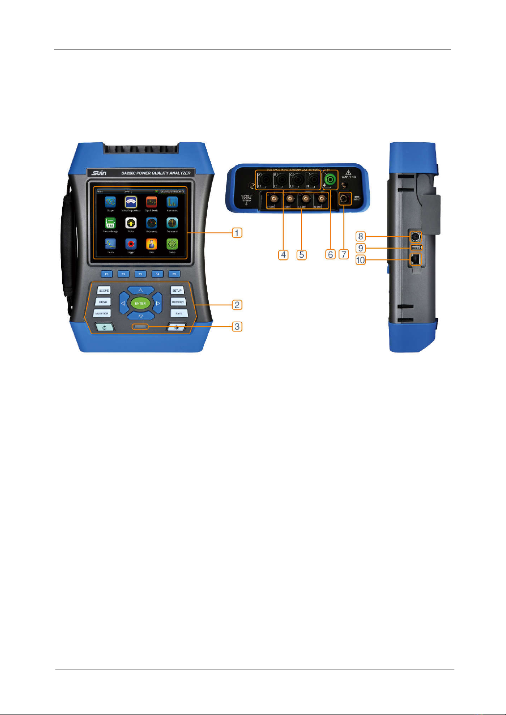
1.1 Overview of the Analyzer
① : display area ⑥: GND input terminal
② : keyboard area ⑦: power adapter interface
③ : charge indicator ⑧: GPS/BEIDOU receiver interface
④ : voltage input terminal ⑨: USB-Host interface
⑤ : input terminal of current clamp ⑩: LAN interface

SA2200 Power Quality Analyzer User’s Guide
Suin Instruments Co.,Ltd. -8-
1.2 Function Description of Keys
1. Power on/ off function. 2. Mandatory
power off: in power on status, press this key
for about 10 seconds, the Analyzer will be
forced to power off.
Brightness adjustment: Press this button
repeatedly to adjust the lightness of the
screen.
Function key: specific function based on
screen menu bar.
Direction key: can move cursor and zoom
waveform
Entry key: press this key to confirm current
select
Oscilloscope shortcut key: fast into the
oscilloscope function.
Main menu shortcut key: enter into main
menu interface quickly.
Monitor function key: enter into monitor
function.
Shortcut key of parameter setting: enter into
interface of parameter setting quickly.
Files management key: enter into files
management interface.
Save key: in measurement status, press this
key to save screenshot and measurement data.
Charge indicator: red: still in charging
green: charge completely
In below text, use【*】to represent corresponding key.
Charge the battery and prepare for use
At delivery, the built in chargeable battery may be empty and it is recommend to charge it
before use. A full charge for the first time takes at least 6 hours. When the charging indicator
SA2200 Power Quality Analyzer User’s Guide
Suin Instruments Co.,Ltd.
-9-
color changing from red to green, it reminds user the battery is fully charged. The Analyzer
automatically cuts off charging when the battery is fully charged. Before use, check that the
adapter voltage and frequency range match the local line power range. To prevent decrease of
batter capacity, charge it at least twice a year.
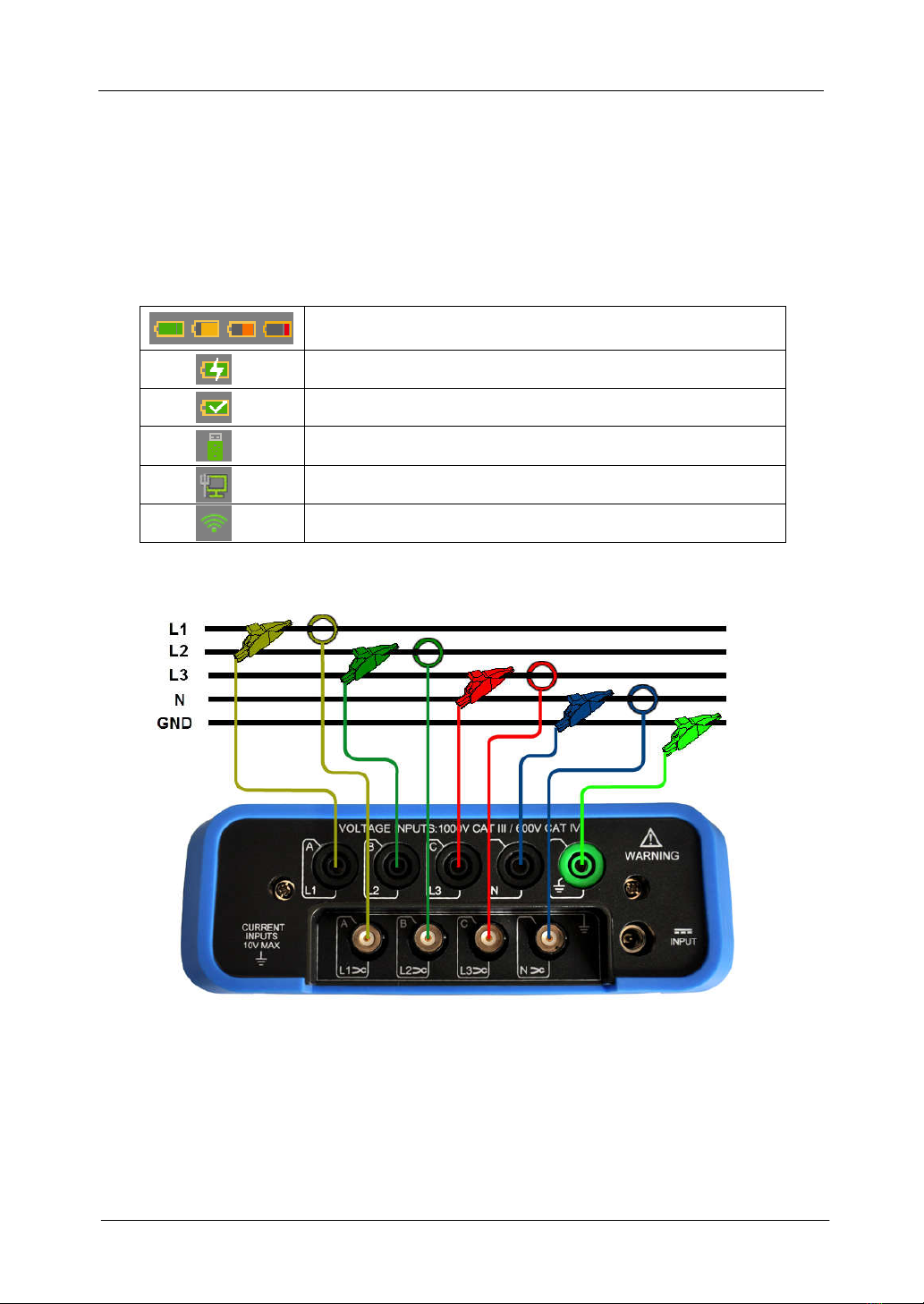
Icon in state indicator bar
1.3 Input Connections
The Analyzer has 4 BNC-inputs for current clamps and 5 banana-inputs for voltages. For a 3-
phase system, make the connections as above picture show.
First put the current clamps around the conductors of phase L1/A, L2/B, L3/C and N.
The clamps are marked with an arrow indicating the correct signal polarity.
Next make the voltage connections: start with GND and then succession N, L1/A, L2/B and
L3/C. For correct measuring results, always connect the Ground input.
Battery capacity indicator, green indicates enough, red
indicates low.
Charge indicator.
Charge Complete.
USB flash disk has connected.
Wired network has connected.
Wireless network has connected.

SA2200 Power Quality Analyzer User’s Guide
Suin Instruments Co.,Ltd. -10-
For single phase measurements, please use current input terminal L1/A, GND, N and voltage
inputs terminal L1/A. Voltage phase L1/A is the reference phase for all measurement.
1.4 Rapid Overview of Measuring Modes
MENU
Below measurements are available with 【MENU】 key:
MONITOR
Press 【MONITOR】key can enter into monitor function, can monitor parameters of RMS,
harmonic, flick, Dips&Swell, interruption, unbalance and frequency. The bar graph screen is as
blow picture shown:

SA2200 Power Quality Analyzer User’s Guide
Suin Instruments Co.,Ltd.
-11-
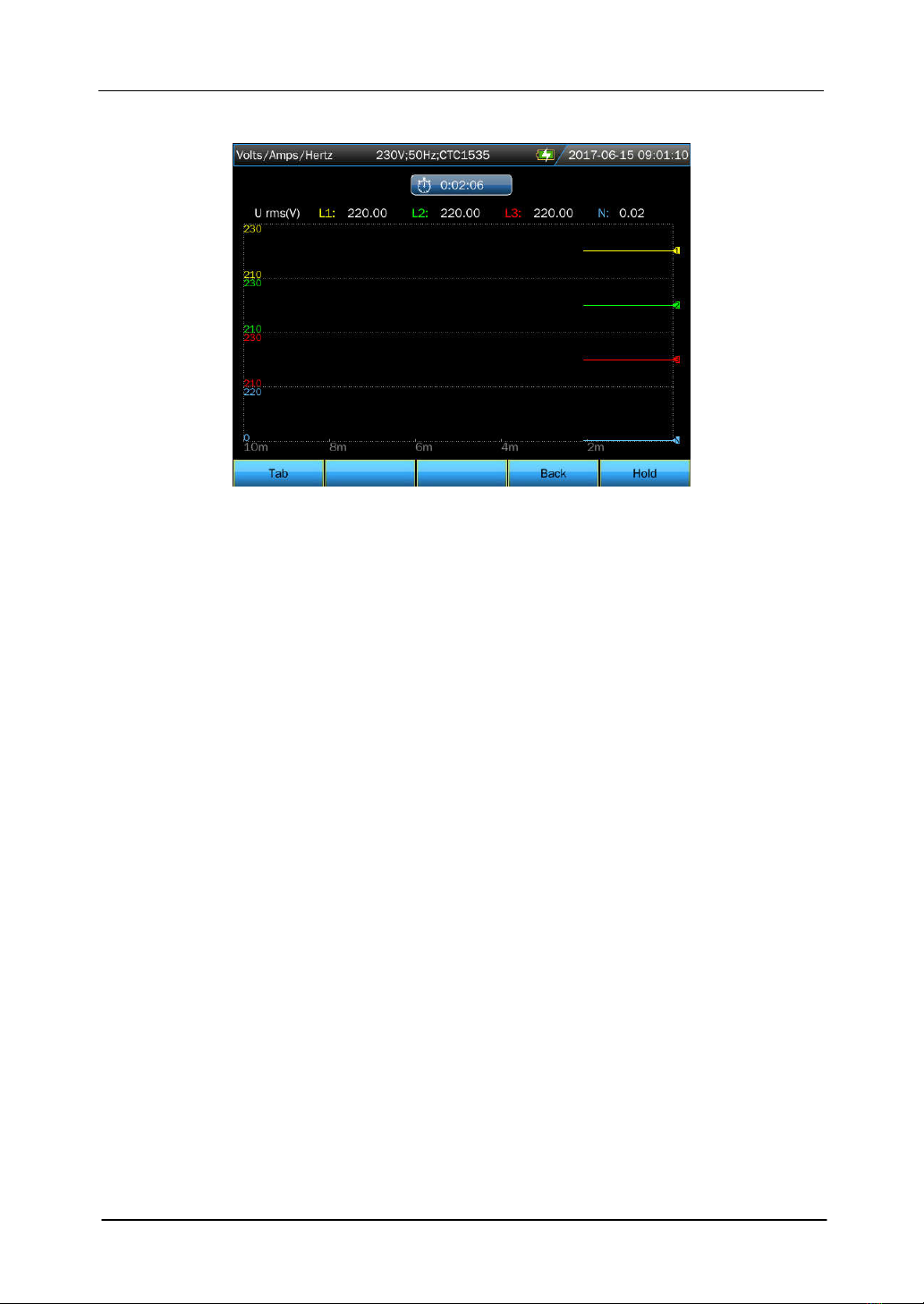
1.5 Screen and Function Keys
The Analyzer has different screen types to present measuring results.
Table screen
Table screen gives an instantaneous overview of important numerical measuring values under
Volts/Amps/Hertz mode.
Screen information:
① The screen header shows current measurement mode, some information will
display in scroll.
② Table in the middle of the screen display the measurement parameters and value,
which depends on measurement mode, phase number and wiring configuration.
③ Function option lies in the bottom of the screen, corresponding to 【F1】~
【F5】key.
Function keys instruction:
【F4】: Open Trend screen.
【F5】: Switch between RUN and HOLD.
SA2200 Power Quality Analyzer User’s Guide
Suin Instruments Co.,Ltd. -12-
Trend screen
Trend screen shows the measurement value which is changing along with time change.
Horizontal axis stands for the time, the Trend chart is forming from screen’s right to left
gradually.
Function key instruction:
【F1】:Switch to the displaying parameters
【F4】:Return to table screen.
【F5】:Switch between RUN and HOLD.
SA2200 Power Quality Analyzer User’s Guide
Suin Instruments Co.,Ltd.
-13-
Chapter 2 Basic Operations
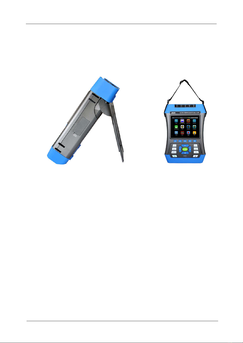
2.1 Tilt Stand and Hang Strap
The tilt stand allows user to view the screen at an angle when place device on a flat surface. A
hang strap is supplied with the Analyzer as below picture show:
2.2 Power on/off
Press the Power key and a single beep can be heard, then the screen shows initial interface.
Press the Power key in power on state, the Analyzer will prompt user whether power off the
device, the device will power off after your confirm.
Mandatory power off: The analyzer will be forced to power off if user press Power key about
10s in power on status.
2.3 Display Brightness
The Analyzer provides 4 degrees of brightness, which is adjustable by pressing the brightness
adjustment key. Low brightness is suggested to save the battery power when powered by the
battery.
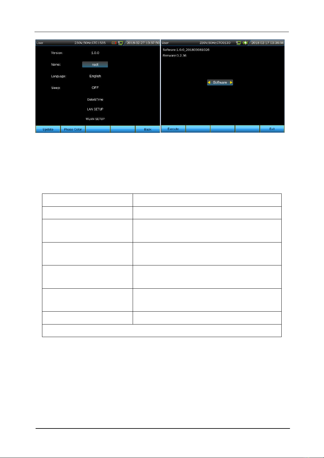
2.4 Update Firmware
If any defective was found during the use of the Analyzer, please contact the customer service
representative to get the update files.
Place the update files under the root directory of U disk, then insert to the Analyzer. After the
U-disk is recognized by device, enter into user configuration interface from main menu, press
【F1】to enter into update interface.
SA2200 Power Quality Analyzer User’s Guide
Suin Instruments Co.,Ltd. -14-
There are tree types of update file including Software, Firmware and System. Select you
wanted files to update, the Analyzer will give prompt after finishing update, then plug out the
U disk, power off the Analyzer then power on to complete the update.
Error codes in right of below table are possible to pop up during update process, coming with
the solution in the left area.
Error code Solution
"ErrCode: 0000 XXXX" May be Flash damage, please replace Flash.
"ErrCode: 0001 XXXX" SPI FLASH model are not supported, please check
the update file.
"ErrCode: 0003" Error Verify of firmware data, please check the
update file.
"ErrCode: 0005 XXXX" Abnormal status, please feedback XXXX to
manufacturer.
"ErrCode: 0010" Serious overtime. Don’t outage and power off. Please
firmware update again.
"ErrCode: 0011" Please try to firmware update again.
XXXX means the detail error message,please feedback to manufacturer.
2.5 Input Connections
Check that the Analyzer setup meets the characteristics of the system under test. This concerns:
wiring configuration, nominal frequency, nominal voltage, current clamp ratio and range.
The Analyzer has 4 BNC inputs for current clamps and 5 banana-inputs for voltages. De-
energize power systems before making connections whenever possible, always use proper
personal safety equipment.
For the connection of 3-phase system, please refer to chapter 1.3.
SA2200 Power Quality Analyzer User’s Guide
Suin Instruments Co.,Ltd.
-15-
2.6 User Settings
User Settings Interface
The user name, language, sleep time, system time, and network setting could be set in this
interface by keys of【▲】【▼】【◄】【►】and【ENTER】keys.
Sleep time: if there is no any key’s operation after setting sleep time and when the setting time
goes off, the brightness of device will be reduced at lowest level automatically, which will
extend the device working time when only battery-powered. Once operate device again, the
brightness can resume to original setting.
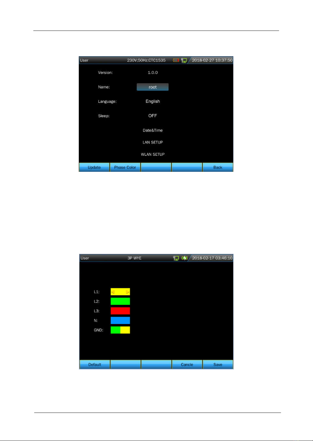
Phase colors
Press 【F2】to set phase color according to local country standard for phase color definition.
Different phase, different color, to represent measurement value of each phase. The default
phase color settings of L1/A, L2/B, L3/C, N and GND separately are yellow, green, red, blue
and green.
SA2200 Power Quality Analyzer User’s Guide
Suin Instruments Co.,Ltd. -16-
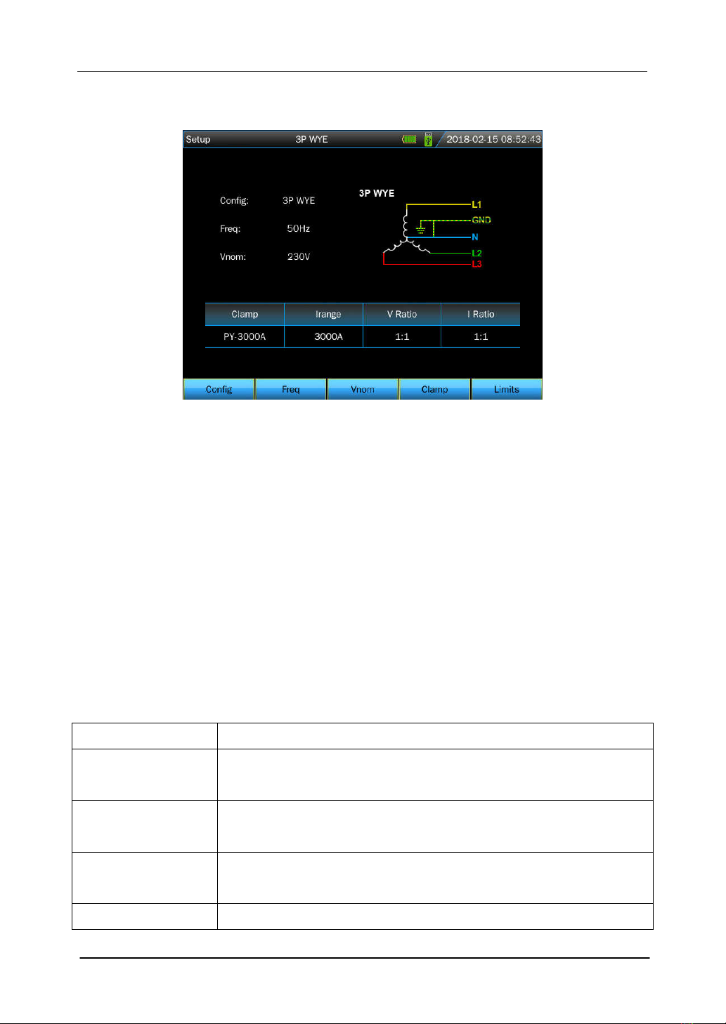
2.7 Setup Analyzer
Setting interface
After power on, current setting will be displayed on the top of the screen. Check if the Date and
Time of the system clock are correct. Also the wiring configuration must match the
configuration of the power system to be checked. The 【SETUP】 key accesses menus to
view and change Analyzer settings.
The settings are grouped in four functional sections which are explained respectively as below:
【F1】: set wiring configuration. 【F2】: set nominal frequency.
【F3】: set nominal voltage. 【F4】: set clamp type.
【F5】: to set monitor limit value: recall, save and define the limit value required in
monitoring the power quality.
Monitor limits
The Analyzer presets a set of limits according to EN50160 standard, and reserves two user-
defined options, which the users can modify under EN50160 standard set of limits and save as
user-defined set of limits.
Limits Adjustments
Voltage 2 probability percentages (100% and adjustable): each with adjustable
upper and lower limits.
Harmonics For 2-25 harmonics and THD 2 probability percentages (100% and
adjustable): each with adjustable upper limit.
Flicker Weighing curve (lamp type). 2 probability percentages (100% and
adjustable): adjustable percentage with adjustable upper limit.
Dips (*) Threshold, hysteresis, allowed number of week.

SA2200 Power Quality Analyzer User’s Guide
Suin Instruments Co.,Ltd.
-17-
Swells (*) Threshold, hysteresis, allowed number of week.
Interruption (*) Threshold, hysteresis, allowed number of week.
Rapid Voltage
Change (*)
Voltage tolerance, steady time, minimum step, minimum rate, allowed
number of week.
Unbalance 2 probability percentages (100% and adjustable): adjustable
percentage with adjustable upper limit.
Frequency 2 probability percentages (100% and adjustable): each with adjustable
upper and lower limits.
(*): Setups are also valid for measuring mode.
2.8 Using Memory and PC
The Analyzer can save screens and data into its memory, and the users can view, delete and
copy them. The Analyzer can also be connected with a PC, through which the remote control of
the Analyzer is available.
SAVE interface
Press 【SAVE】key can save current screenshot or measurement data.
Use 【▲】【▼】keys to select the type of the saved files.
Use 【ENTER】key to enter into edit interface to edit the file name.
Press 【F5 】to complete the saving, and return to the original interface.
MEMORY interface

SA2200 Power Quality Analyzer User’s Guide
Suin Instruments Co.,Ltd. -18-
The MEMORY button accesses to the save list interface, which shows the save time, name and
type of saved files. Press【▲】【▼】 keys to select specified files. After accessing to the
save interface, insert a U disk and wait for a few seconds, then U disk icon display on the state
bar, then “TO USB” characters become lighted, press 【F2】 to copy the current selected flies
to the U disk, then there is a progress bar to prompt the copy process,. When finish the copy,
plug off the U disk then inset it to the PC to view.
Function keys instruction:
【F2】:Copy file to U disk after inserting a U disk and the characters of the key become
lighted.
【F3】: View selected saved file.
【F4】: Delete selected saved file.
【F5】: Return to previous interface.
Using PC software
Installation requirement of PQA_Setup
CPU: processor over 1GHz.
Memory: over 2G.
Displayer: VGA or higher resolution monitor (resolution 1024×768 or above is
recommended).
Hard disk: over 100M.
Network card: 10M/100M network card.
Operating system: Windows Vista or high version.
Microsoft Office version: Office 2007 or above.
SA2200 Power Quality Analyzer User’s Guide
Suin Instruments Co.,Ltd.
-19-
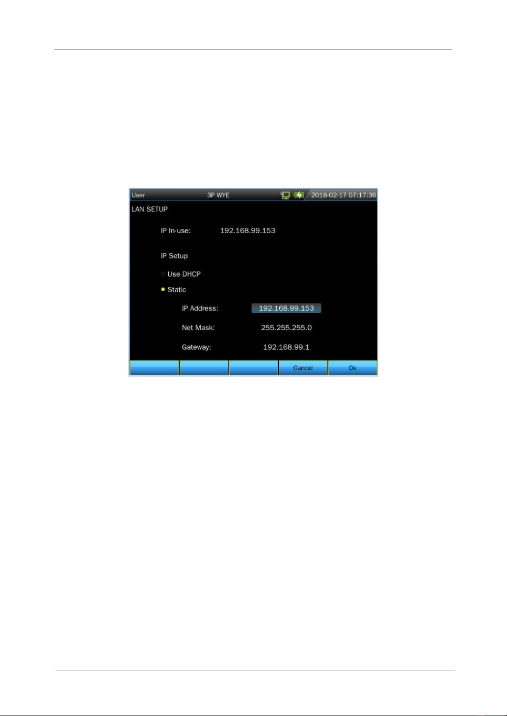
Network Settings
The LAN interface is configured to realize communication between device and PC.
The Analyzer is equipped with a LAN interface for communication with a PC. With supplied
PC software, user can remote control analyzer, download saved files, analyze the data and
create report on PC. In additional, user can also use the PC software to view the data and
screenshot copied from a U disk.
Select 【LAN SETUP】in 【User】option as below picture shown:
Connect the Analyzer with PC by one piece of net cable, set IP address of Analyzer and PC to
different, but should be in the same network segment. For example: IP address in PC is
192.168.1.XXX, while IP address in the Analyzer also should be 192.168.1.XXX accordingly.
After a correct setting IP address for the analyzer, access the analyzer to the network by one
new cable. Open PQA View software, select 【auto connection】or 【manual connection】
(input IP address manually )in 【file】option, after a successful connecting, an operating
interface which simulate the analyzer will pop up and user can download the saved file in
device as below picture shown.
Table of contents
Other Suin Measuring Instrument manuals


