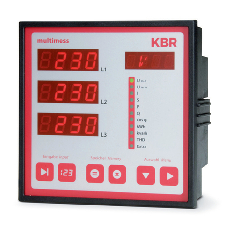
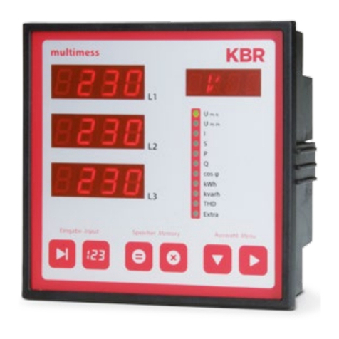
KBR multisys 1D3-ESDP Operating instructions

1D3-ESDP
multisys
Your Partner for
Network Analyzing
Operating Instructions
Technical Parameters

KBR GmbH
Am Kiefernschlag 7
D-91126 Schwabach
T +49 (0) 9122 6373-0
F +49 (0) 9122 6373-83
E info@kbr,de
www.kbr.de

Page I von IV
3510-1 GB
Dear Customer
We would like to thank you for choosing a KBR GmbH quality product.
In order to familiarize yourself with the operation and programming of the device and always be able to use the
whole functionality of this high-quality product, we recommend that you read this manual thoroughly.
The individual chapters serve to explain the technical details of the device and show how to avoid damage by
means of proper installation and commissioning.
The manual is included in the scope of delivery of the device and must be accessible for the user at all times
(e.g. in the switchgear cabinet). Even when the device is resold to third parties, the manual remains part of the
device.
Although we used the utmost care in assembling this manual, we would like to thank you in advance for notify-
ing us about any errors or ambiguous descriptions that might be in it. You will find a form for corrections in the
appendix.
Sincerely,
KBR GmbH Schwabach
Preface

Page II von IV
3510-1 GB
Safety Precautions
This manual contains notes that must be observed for your personal safety and to avoid damage to equipment.
Notes are identified by a warning sign or an info symbol according to the degree of hazard they represent.
Disclaimer
The contents of this manual has been checked with the described hardware and software components. Cer-
tain deviations, however, cannot be excluded, so the manufacturer is not liable for complete conformity. The
specifications made in this manual are checked on a regular basis, necessary corrections are included in the
next revision.
We appreciate your corrections and comments.
© KBR-GmbH
Subject to change
aDanger
means that death, major injuries or damage will occur in case the
appropriate safety measures are not performed.
aWarning
means that death, major injuries or damage may occur in case the
appropriate safety measures are not performed.
aCaution
means that minor injuries or damage may occur in case the appropriate
safety measures are not performed.
bNote
is an important information on the product, product handling or the
respective part of the user manual to which special reference is made.
Safety Precautions

Page III von IV
3510-1 GB
General Safety Precautions
In order to prevent operating errors, handling of the device is kept as simple as possible. This way, you will be
able to use the device very soon.
In your own interest, however, you should read the following safety precautions carefully.
aWarning
During installation, the applicable DIN / VDE regulations must be obser-
ved!
Mains connection, setup and operation of the device must only be per-
formed by qualified personnel. Qualified personnel as understood in the
safety precautions of this manual are persons authorized to setup,
ground and mark equipment, systems and wiring systems in
accordance with applicable standards.
To avoid the hazard of fire and electrical shock, the device must not be
subjected to rain or other humidity!
Before the device is connected to the mains, you will have to check
whether the local mains conditions comply with the specifications on the
manufacturer's label. A wrong connection may destroy the device!
When connecting the device, the connection chart must be observed
(see chapter "Connection chart") and the connection lines must be pow-
erless. Only use proper line material and watch the correct polarity
when wiring!
In order to ensure proper and safe operation of the product, it must be
transported, stored, installed and mounted in accordance with the speci-
fications and operated and maintained carefully.
A device showing visible damage must by all means be considered as
unfit for operation and must be disconnected from the mains!
Error detection, repairs and maintenance work may only be carried out
in our facilities or after contacting our service team. Every warranty obli-
gation of the manufacturer expires if the device is opened without writ-
ten consent from our service team. Proper operation can no longer be
guaranteed!
Opening the device may expose parts under voltage. Capacitors in the
device may still be loaded even if the device was disconnected from all
voltage sources. It is generally not allowed to operate the open device!
In facilities subject to hazard of lightning, lightning protection must be
provided for all input and output lines (recommendations see chapter
"Protective measures")!
Safety Precautions
Page IV von IV
3510-1 GB
Product Liability
With these product, you have acquired a quality product.
In its manufacture, only components of the highest reliability and quality were used. Each device is subject to
long-term testing before it is delivered.
For information on product liability, please refer to our General Terms and Conditions for electronic devices.
The warranted properties of the device apply only if it is operated in accordance with its intended use!
Disposal
Please dispose of defective, outdated or no longer used devices properly.
At your request, we will be pleased to dispose of the devices for you.
Product Liability / Disposal

MULTIGATE-Profibus / multisys 1D3-ESDP
Version 1.0 Page - 1 -
EDEBDA0055 / 4210-1 GB
Table of Contents
1 Description ...................................................................................................2
2 Function .......................................................................................................3
3 Connection ...................................................................................................3
4 Configuration ...............................................................................................4
4.1 Profibus address .................................................................................................... 4
5 Commissioning ...........................................................................................6
6 Data formats ................................................................................................6
7 GSD file ........................................................................................................9
7.1 Example for integration into a Simatic S7-300 control ....................................... 9
8 multimess 1F96-0-LED-ES-US1 ................................................................10
8.1 GSD file for multimess 1F96-0-LED-ES-US1 ...................................................... 10
8.2 Output data MULTIMESS-96-Basic ..................................................................... 13
8.3 Input data multimess 1F96-0-LED-ES-US1 ......................................................... 14
9 multicount basic LCD bus ........................................................................17
9.1 GSD file for multicount basic LCD bus .............................................................. 17
9.2 Output data multicount basic LCD bus .............................................................. 20
9.3 Input datamulticount basic LCD bus .................................................................. 21
10 Reactive energy controller BK12 Basic ..................................................23
10.1 GSD file for BK12 Basic ....................................................................................... 23
10.2 Output data BK12 ................................................................................................. 25
10.3 Input data BK12 .................................................................................................... 25
11 Reactive power controller multicomp 96 LCD bus .................................28
11.1 GSD file for multicomp 96 LCD bus .................................................................... 28
11.2 Output data multicomp 96 LCD bus ................................................................... 30
11.3 Input data multicomp 96 LCD bus ...................................................................... 30

MULTIGATE-Profibus / multisys 1D3-ESDP
Page - 2 - Version 1.0
EDEBDA0055 / 4210-1 GB
1 Description
The KBR MULTIGATE-Profibus / multisys 1D3-ESDP connects the KBR energy bus to a Profibus. The two
interfaces are isolated galvanically from each other.
The gateway allows the KBR multimess 1F96-0-LED-ES-US1, multicount basic LCD bus, BK12 Basic or
a multicomp 96 LCD bus to be read out via the Profibus. Communication between the device and the gateway
takes place via the KBR Energy Bus. Either a multimess 1F96-0-LED-ES-US1, multicount basic LCD bus
BK12 Basic or a multicomp 96 LCD bus can be connected with the fixed energy bus address 1. The Profibus
address can be configured via DIP switches on the gateway.The gateway here is configured as the master on the
energy bus side, generates a memory map for the corresponding device and makes this available as data points
for the Profibus. The number and type of the data points can be conveniently configured via the GSD file.
Figure 1: Principal system design

MULTIGATE-Profibus / multisys 1D3-ESDP
Version 1.0 Page - 3 -
EDEBDA0055 / 4210-1 GB
2 Function
The MULTIGATE-Profibus / multisys 1D3-ESDP continually polls its connected multimess 1F96-0-LED-
ES-US1, multicount basic LCD bus, BK12 Basic or multicomp 96 LCD bus to receive its measured values.
It then saves these inthe internal memory. Themeasured values are now ready forretrieval by the Profibus. After
the device has been configured by a Profibus master, it makes available the values in the cyclic data exchange.
3 Connection
The power supply for the MULTIGATE-Profibus / multisys 1D3-ESDPis provided by a power pack with 24V
AC/DC supplied by the customer. 24V are connected to the 24V AC/DC input.
The Energy Bus is wired up in accordance with the KBR eBus guideline. Connection to the Profibus DP network
is estabilshed via 9-pole standard Profibus plugs.
Figure 2: Pin assignment
Power
supply
EBUS
1
A
1
24V
ac/dc
B
1
PROCESS FIELD BUS
®
PROFIBUS-DP

MULTIGATE-Profibus / multisys 1D3-ESDP
Page - 4 - Version 1.0
EDEBDA0055 / 4210-1 GB
4 Configuration
On the side of the housing opposite the connections the DIP switch S1 is located under a cover. This is used to
set the Profibus address:
Figure 3: DIP switch for parametrization
12345678
ON
S1
Note:Changesmayonlybemadetotheconfiguration
when the unit is switched off.
4.1 Profibus address
The DIP switch S1 is used to set the Profibus
address. It can be set in the range from 1 to 125.
DIP switch 1 Profibus
address
12345678
OFFOFFOFFOFFOFFOFFOFF ON 1
OFF OFF OFF OFF OFF OFF ON OFF 2
OFFOFFOFFOFFOFFOFF ON ON 3
OFF OFF OFF OFF OFF ON OFF OFF 4
OFF OFF OFF OFF OFF ON OFF ON 5
OFF OFF OFF OFF OFF ON ON OFF 6
OFF OFF OFF OFF OFF ON ON ON 7
OFF OFF OFF OFF ON OFF OFF OFF 8
OFF OFF OFF OFF ON OFF OFF ON 9
OFF OFF OFF OFF ON OFF ON OFF 10
OFF OFF OFF OFF ON OFF ON ON 11
OFF OFF OFF OFF ON ON OFF OFF 12
OFF OFF OFF OFF ON ON OFF ON 13
OFF OFF OFF OFF ON ON ON OFF 14
OFF OFF OFF OFF ON ON ON ON 15
OFF OFF OFF ON OFF OFF OFF OFF 16
OFF OFF OFF ON OFF OFF OFF ON 17
OFF OFF OFF ON OFF OFF ON OFF 18
OFF OFF OFF ON OFF OFF ON ON 19
OFF OFF OFF ON OFF ON OFF OFF 20
OFF OFF OFF ON OFF ON OFF ON 21
OFF OFF OFF ON OFF ON ON OFF 22
OFF OFF OFF ON OFF ON ON ON 23
OFF OFF OFF ON ON OFF OFF OFF 24
OFF OFF OFF ON ON OFF OFF ON 25
OFF OFF OFF ON ON OFF ON OFF 26
OFF OFF OFF ON ON OFF ON ON 27
OFF OFF OFF ON ON ON OFF OFF 28
OFF OFF OFF ON ON ON OFF ON 29
OFF OFF OFF ON ON ON ON OFF 30
OFF OFF OFF ON ON ON ON ON 31
OFF OFF ON OFF OFF OFF OFF OFF 32
OFF OFF ON OFF OFF OFF OFF ON 33
Table 1: Profibus address

MULTIGATE-Profibus / multisys 1D3-ESDP
Version 1.0 Page - 5 -
EDEBDA0055 / 4210-1 GB
OFF OFF ON OFF OFF OFF ON OFF 34
OFF OFF ON OFF OFF OFF ON ON 35
OFF OFF ON OFF OFF ON OFF OFF 36
OFF OFF ON OFF OFF ON OFF ON 37
OFF OFF ON OFF OFF ON ON OFF 38
OFF OFF ON OFF OFF ON ON ON 39
OFF OFF ON OFF ON OFF OFF OFF 40
OFF OFF ON OFF ON OFF OFF ON 41
OFF OFF ON OFF ON OFF ON OFF 42
OFF OFF ON OFF ON OFF ON ON 43
OFF OFF ON OFF ON ON OFF OFF 44
OFF OFF ON OFF ON ON OFF ON 45
OFF OFF ON OFF ON ON ON OFF 46
OFF OFF ON OFF ON ON ON ON 47
OFF OFF ON ON OFF OFF OFF OFF 48
OFF OFF ON ON OFF OFF OFF ON 49
OFF OFF ON ON OFF OFF ON OFF 50
OFF OFF ON ON OFF OFF ON ON 51
OFF OFF ON ON OFF ON OFF OFF 52
OFF OFF ON ON OFF ON OFF ON 53
OFF OFF ON ON OFF ON ON OFF 54
OFF OFF ON ON OFF ON ON ON 55
OFF OFF ON ON ON OFF OFF OFF 56
OFF OFF ON ON ON OFF OFF ON 57
OFF OFF ON ON ON OFF ON OFF 58
OFF OFF ON ON ON OFF ON ON 59
OFF OFF ON ON ON ON OFF OFF 60
OFF OFF ON ON ON ON OFF ON 61
OFF OFF ON ON ON ON ON OFF 62
OFF OFF ON ON ON ON ON ON 63
OFF ON OFF OFF OFF OFF OFF OFF 64
OFF ON OFF OFF OFF OFF OFF ON 65
OFF ON OFF OFF OFF OFF ON OFF 66
OFF ON OFF OFF OFF OFF ON ON 67
OFF ON OFF OFF OFF ON OFF OFF 68
OFF ON OFF OFF OFF ON OFF ON 69
OFF ON OFF OFF OFF ON ON OFF 70
OFF ON OFF OFF OFF ON ON ON 71
OFF ON OFF OFF ON OFF OFF OFF 72
OFFONOFFOFFONOFFOFFON 73
OFF ON OFF OFF ON OFF ON OFF 74
OFFONOFFOFFONOFFON ON 75
OFF ON OFF OFF ON ON OFF OFF 76
OFFONOFFOFFON ONOFFON 77
OFF ON OFF OFF ON ON ON OFF 78
OFFONOFFOFFON ON ON ON 79
OFF ON OFF ON OFF OFF OFF OFF 80
OFF ON OFF ON OFF OFF OFF ON 81
OFF ON OFF ON OFF OFF ON OFF 82
OFF ON OFF ON OFF OFF ON ON 83
OFF ON OFF ON OFF ON OFF OFF 84
DIP switch 1 Profibus
address
12345678
Table 1: Profibus address (cont.)
OFF ON OFF ON OFF ON OFF ON 85
OFF ON OFF ON OFF ON ON OFF 86
OFF ON OFF ON OFF ON ON ON 87
OFF ON OFF ON ON OFF OFF OFF 88
OFF ON OFF ON ON OFF OFF ON 89
OFF ON OFF ON ON OFF ON OFF 90
OFF ON OFF ON ON OFF ON ON 91
OFF ON OFF ON ON ON OFF OFF 92
OFF ON OFF ON ON ON OFF ON 93
OFF ON OFF ON ON ON ON OFF 94
OFF ON OFF ON ON ON ON ON 95
OFF ON ON OFF OFF OFF OFF OFF 96
OFF ON ON OFF OFF OFF OFF ON 97
OFF ON ON OFF OFF OFF ON OFF 98
OFF ON ON OFF OFF OFF ON ON 99
OFF ON ON OFF OFF ON OFF OFF 100
OFFON ONOFFOFFONOFFON 101
OFF ON ON OFF OFF ON ON OFF 102
OFFON ONOFFOFFON ON ON 103
OFF ON ON OFF ON OFF OFF OFF 104
OFF ON ON OFF ON OFF OFF ON 105
OFF ON ON OFF ON OFF ON OFF 106
OFF ON ON OFF ON OFF ON ON 107
OFF ON ON OFF ON ON OFF OFF 108
OFF ON ON OFF ON ON OFF ON 109
OFF ON ON OFF ON ON ON OFF 110
OFF ON ON OFF ON ON ON ON 111
OFF ON ON ON OFF OFF OFF OFF 112
OFF ON ON ON OFF OFF OFF ON 113
OFF ON ON ON OFF OFF ON OFF 114
OFFONONONOFFOFFONON 115
OFF ON ON ON OFF ON OFF OFF 116
OFFONONONOFFONOFFON 117
OFF ON ON ON OFF ON ON OFF 118
OFF ON ON ON OFF ON ON ON 119
OFF ON ON ON ON OFF OFF OFF 120
OFFONONONONOFFOFFON 121
OFF ON ON ON ON OFF ON OFF 122
OFF ON ON ON ON OFF ON ON 123
OFF ON ON ON ON ON OFF OFF 124
OFFONONONONONOFFON 125
DIP switch 1 Profibus
address
12345678
Table 1: Profibus address (cont.)

MULTIGATE-Profibus / multisys 1D3-ESDP
Page - 6 - Version 1.0
EDEBDA0055 / 4210-1 GB
5 Commissioning
After the configuration and all the wiring have been successfully completed, the MULTIGATE-Profibus /
multisys 1D3-ESDP can be put into operation. Here it should be ensured that the gateway is the final device to
be switched on, or that the KBR eBus device and gateway are supplied with power at the the same time. The
gateway can now be found on the Profibus under the address set, and it can be parametrized and configured via
a suitable configuration tool.
6 Data formats
(unsigned) short :0x1234
Rule for byte sequence:
MSB before LSB
(unsigned) long:0x12345678
Rule for byte sequence:
MSB before LSB
float:
Address +0 +1
Contents 0x12 0x34
Table 2: unsigned short
Address +0 +1 +2 +3
Contents 0x12 0x34 0x56 0x78
Table 3: unsigned long
Format corresponds to the IEEE 754 standard
Representation 4 bytes
Accuracy 24 bits (¾represent >7 decimal points)
Composition 24-bit mantissa; 8-bit exponent
Mantissa 23 bits (M) + 1 bit (S)
The MSB of the mantissa always amounts to 1 => it is not saved separately!
S = sign for the mantissa: S = 1 ¾negative number; S = 0 ¾positive
number
Exponent 8 bits (0-255); is saved relative to 127, ie. the current value of the exponent
is deduced by subtracting the number 127 from the value saved.
Curr. exp. = saved value of exp. – 127 => Number range from 128 to -127!
Numeric range which can be represented:
1.18E-38 to 3.40E+38
Table 4: float

MULTIGATE-Profibus / multisys 1D3-ESDP
Version 1.0 Page - 7 -
EDEBDA0055 / 4210-1 GB
Example 1: -12.5 decimal = 0xC1480000 hex
M: 24-bit mantissa
E: Exponent with an offset of 127
S: Sign for mantissa (S=1 neg.; S=0 pos.)
The byte sequence ist defined as follows:
The byte with the "S sign bit“ is transmitted as the first byte via the bus.
The sequence of the float bytes on the bus can be reversed, where required, using the "commands“ module (see
table 1).
The following information can be derived from this illustration:
The sign bit is 1 => negative mantissa
The value of the exponent amounts to 10000010 bin or 130 dec.
This yields a value for the exponent of: 130 - 127 = 3
The mantissa contains the following value: 10010000000000000000000
The decimal point can be found at the left end of the mantissa, preceded by a 1. This position does not appear in
the hexadecimal numeric notation. If you add 1 and set the decimal point at the beginning of the mantissa, you
will obtain the following value:
1.10010000000000000000000
Now the mantissa must be adjusted to the exponent. A negative exponent shifts the decimal point to the left, a
positive exponent shifts it to the right. Since the exponent is 3, this appears in our illustration as:
1100.10000000000000000000
The number obtained corresponds to the binary floating-point number.
Binary points to the left of the decimal point yield values > 1. In this example, 1100 bin yields the number 12 dec.
{(1x23)+ (1x22)+ (0x21)+ (0x20)}
Binary points to the right of the decimal point yield values < 1. In this example, .100....... bin yields the number 0.5
dec. {(1x23)+ (1x2-1)+ (0x2-2)+ (0x2-3)}
By adding the individual values, 12.5 is obtained. Since the sign bit was set, this is a negative number, that is, -
12.5. The hexadecimal number 0xC1480000 therefore corresponds to -12.5.
Example 2: -12.55155 decimal = 0xC148D325 hex
Address +0 +1 +2 +3
Format SEEEEEEE EMMMMMMM MMMMMMMM MMMMMMMM
Binary 1 1 0 0 0 0 0 1 0 1 0 0 1 0 0 0 0 0 0 0 0 0 0 0 0 0 0 0 0 0 0 0
Hex C1 48 00 00
Table 5: Example float -12.5
Address +0 +1 +2 +3
Format SEEEEEEE EMMMMMMM MMMMMMMM MMMMMMMM
Binary 1 1 0 0 0 0 0 1 0 1 0 0 1 0 0 0 1 1 0 1 0 0 1 1 0 0 1 0 0 1 0 1
Hex C1 48 D3 25
Table 6: Example float -12.55155

MULTIGATE-Profibus / multisys 1D3-ESDP
Page - 8 - Version 1.0
EDEBDA0055 / 4210-1 GB
Example 3: 45.354 decimal = 0x42356A7F hex
Exponent: 10000100 bin = 132 dec.
¾Exp.= 132-127=5
Mantissa: S=0
¾VZ=positive
01101010110101001111111 bin
Decimal point added to the first position of the mantissa
¾. 01101010110101001111111
Leading 1 before of decimal point
¾1. 01101010110101001111111
Taking exponent into account (=5)
¾101101. 010110101001111111
to the left of the decimal point: 101101 bin = 25+ 23+ 22+20= 45 dez.
to the right of the decimal point: 010110101001111111 bin =
2-2 + 2-4 + 2-5 + 2-7 + 2-9 + 2-12 + 2-13 + 2-14 + 2-15 + 2-16 + 2-17 + 2-18 = 0.3540001 dec.
Final result: +45.3540001 dec
Time stamp time_t (is transmitted as unsigned long)
The time stamp describes a point in time. The value here is defined as follows:
Seconds since 1.1.1970 0°° hours (with respect to the appropriate time zone)
The values are transmitted via the bus as unsigned long (for byte sequence, see above). All values here are to
be interpreted as standard time (winter time), ie. if you want to set the device clock in Germany to 11 o'clock in
May, then the setting command via the bus must be given, by definition, with winter time 10 o'clock.
The following applies:
All time stamps which are transmitted via the bus are to be interpreted as standard (winter) time.
The device itself must be parametrized here in accordance with country-specific practices.
Possible settings here:
e.g.: Germany -> daylight saving time from end of March to end of October
e.g. China -> daylight saving time not activated
Address +0 +1 +2 +3
Format SEEEEEEE EMMMMMMM MMMMMMMM MMMMMMMM
Binary 0 1 0 0 0 0 1 0 0 0 1 1 0 1 0 1 0 1 1 0 1 0 1 0 0 1 1 1 1 1 1 1
Hex 42 35 6A 7F
Table 7: Example float 45.354

MULTIGATE-Profibus / multisys 1D3-ESDP
Version 1.0 Page - 9 -
EDEBDA0055 / 4210-1 GB
7 GSD file
The functionality of the device is describedby the GSD file. The MULTIGATE Profibus / multisys 1D3-ESDP
represents its connected KBR device as a modular device.
By lining up the desired modules using the configuration data, the input and output data can be put together any
way you like. The offfset for the respective values in the input data is derived from the length of the data formats
specified in each case.
Depending on the device connected, a different GSD file is used. Detection takes place automatically. This means
that if a multimess 1F96-0-LED-ES-US1 is connected, for example, the gateway also announces itself as a
multimess 1F96-0-LED-ES-US1. The configuration tool then provides the modules for selection for this device.
7.1 Example for integration into a Simatic S7-300 control
Since the 300-type controls from the Siemens company cannot process any consistent data of 3 or >4 bytes, the
data have to be read using SFC14. This is the case for the multimess 1F96-0-LED-ES-US1 and multicount
basic LCD bus devices, because these all supply three-phase measured values as 12-byte modules. For the
BK12 Basic it is not required to use SFC14, since all modules are 4 bytes in length (see first block in the
example).
// In the hardware configurator the "Frequency" module was configured to the input address 24.
// This module is 4-bytes in length (consistent) and can therefore be
// evaluated immediately
L ED 24 // Frequency
T MD 24
// The module "Voltage PH-N L1-L3" was configured to the input address 0 and
// the module "Current L1-L3" was configured to the input address 12.
// These modules each have 12 bytes of consistent length (3 * 4 bytes real) and can
// be read out using SFC14.
CALL "DPRD_DAT" // SFC 14
LADDR :=W#16#0 // configured E-address of the module
RET_VAL:=MW120 // any measured value for possible error codes
RECORD :=P#DB4.DBX0.0 BYTE 12 // Pointer target area of data
L DB4.DBD 0 // U L1
T MD 0
L DB4.DBD 4 // U L2
T MD 4
L DB4.DBD 8 // U L3
T MD 8
CALL "DPRD_DAT" // SFC 14
LADDR :=W#16#C // configured E-address of the module
RET_VAL:=MW120 // any measured value for possible error codes
RECORD :=P#DB4.DBX12.0 BYTE 12 // Pointer target area of data
L DB4.DBD 12 // 1 L1
T MD 12
L DB4.DBD 16 // 1 L2
T MD 16
L DB4.DBD 20 // 1 L3
T MD 20

MULTIGATE-Profibus / multisys 1D3-ESDP
Page - 10 - Version 1.0
EDEBDA0055 / 4210-1 GB
8 multimess 1F96-0-LED-ES-US1
8.1 GSD file for multimess 1F96-0-LED-ES-US1
;-----------------------------------------------------------------------------;
; GSD Multimess 96 for PROFIBUS DP ;
; Fa. KBR GmbH, Am Kiefernschlag 7 , 91126 Schwabach ;
; Tel.: 09122/6373-0 ;
; Date: 30.04.2004 ;
;-----------------------------------------------------------------------------;
#Profibus_DP
; <Prm-Text-Def-List>
PrmText=1
Text(0)= "do not rotate float/REAL"
Text(1)= "rotate float/REAL"
EndPrmText
; <Ext-User-Prm-Data-Def-List>
ExtUserPrmData=1 "float/REAL byte rotation"
Bit(0) 0 0-1
Prm_Text_Ref=1
EndExtUserPrmData
;
GSD_Revision = 2
Vendor_Name = "KBR GmbH, Schwabach" ; company name
Model_Name = "Multimess 96 Basic" ; device name
Revision = "1.0" ; device release
Ident_Number = 0x08F7 ; priliminary ident number
Protocol_Ident = 0 ; PROFIBUS_DP Protokoll
Station_Type = 0 ; slave station
Hardware_Release = "V1.0" ;
Software_Release = "V1.00" ;
9.6_supp = 1 ; Baudrate 9.6kB supported
19.2_supp = 1 ; Baudrate 19.2kB supported
93.75_supp = 1 ; Baudrate 93.75kB supported
187.5_supp = 1 ; Baudrate 187.5kB supported
500_supp = 1 ; Baudrate 500kB supported
1.5M_supp = 1 ; Baudrate 1.5MB supported
3M_supp = 1 ; Baudrate 3MB supported
6M_supp = 1 ; Baudrate 6MB supported
12M_supp = 1 ; Baudrate 12 MB supported
MaxTsdr_9.6 = 60
MaxTsdr_19.2 = 60
MaxTsdr_93.75 = 60
MaxTsdr_187.5 = 60
MaxTsdr_500 = 100
MaxTsdr_1.5M = 150
MaxTsdr_3M = 250
MaxTsdr_6M = 450
MaxTsdr_12M = 800
Freeze_Mode_supp = 0 ; no Freeze Mode
Sync_Mode_supp = 0 ; no Sync Mode
Auto_Baud_supp = 1 ; automatic baudrate
Set_Slave_Add_supp = 0 ; no addressing over BUS
Min_Slave_Intervall = 6 ; min. slave-poll-cycle
Modular_Station = 1 ; modular concept
Redundancy = 0
Repeater_Ctrl_Sig = 0
24V_Pins = 0
Max_Diag_Data_Len = 30 ;
Max_Module = 40 ;
Slave_Family = 0 ;
Max_Data_Len = 246 ;
Max_Input_Len = 244 ;
Max_Output_Len = 2 ;

MULTIGATE-Profibus / multisys 1D3-ESDP
Version 1.0 Page - 11 -
EDEBDA0055 / 4210-1 GB
;
; <Parameter-Definition-List>
;User_Prm_Data_Len = 4
;User_Prm_Data = 0x00,0x00,0x00,0x00
Max_User_Prm_Data_Len = 4
Ext_User_Prm_Data_Ref(3)=1
Module="device status (read and reset)" 0x91,0xA0 ; reset status with <> 0 in Outputdata
EndModule
Module="clear-commands" 0xA0 ; Bit0: reserved
; Bit1: reserved
; Bit2: reset endless active work counter
consumption
; Bit3: reset endless reactive work counter
consumption
; Bit4: reserved
; Bit5: reserved
; Bit6: reserved
; Bit7: reserved
EndModule
; 0123456789abcdef0123456789ABCDEF" Unit Format Size
Module="voltage PH-N L1-L3" 0x41,0x8B, 1 ; V float 12
EndModule
Module="voltage PH-PH L1-L3" 0x41,0x8B, 2 ; V float 12
EndModule
Module="current L1-L3" 0x41,0x8B, 3 ; A float 12
EndModule
Module="current average. L1-L3" 0x41,0x8B, 4 ; A float 12
EndModule
Module="apparent power L1-L3" 0x41,0x8B, 5 ; kVA float 12
EndModule
Module="active power L1-L3" 0x41,0x8B, 6 ; kW float 12
EndModule
Module="reactive power (Q1) L1-L3" 0x41,0x8B, 7 ; kvar float 12
EndModule
Module="reactive power (Qn) L1-L3" 0x41,0x8B, 8 ; kvar float 12
EndModule
Module="cos Phi L1-L3" 0x41,0x8B, 9 ; - float 12
EndModule
Module="powerfactor L1-L3" 0x41,0x8B, 10 ; - float 12
EndModule
Module="max: voltage PH-N L1-L3" 0x41,0x8B, 11 ; V float 12
EndModule
Module="max: voltage PH-PH L1-L3" 0x41,0x8B, 12 ; V float 12
EndModule
Module="max: current L1-L3" 0x41,0x8B, 13 ; A Float 12
EndModule
Module="max: current average. L1-L3" 0x41,0x8B, 14 ; A float 12
EndModule
Module="max: apparent power L1-L3" 0x41,0x8B, 15 ; kVA float 12
EndModule
Module="max: active power L1-L3" 0x41,0x8B, 16 ; kW float 12
EndModule
Module="max: reactive power (Q1) L1-L3" 0x41,0x8B, 17 ; kvar float 12
EndModule
Module="max: reactive power (Qn) L1-L3" 0x41,0x8B, 18 ; kvar float 12
EndModule
Module="max: cos Phi L1-L3" 0x41,0x8B, 19 ; - float 12
EndModule
Module="max: powerfactor L1-L3" 0x41,0x8B, 20 ; - float 12
EndModule
Module="min: voltage PH-N L1-L3" 0x41,0x8B, 21 ; V float 12
EndModule
Module="min: voltage PH-PH L1-L3" 0x41,0x8B, 22 ; V float 12
EndModule
Module="min: current L1-L3" 0x41,0x8B, 23 ; A Float 12
EndModule
Module="min: current average. L1-L3" 0x41,0x8B, 24 ; A float 12
EndModule
Module="min: apparent power L1-L3" 0x41,0x8B, 25 ; kVA float 12
EndModule

MULTIGATE-Profibus / multisys 1D3-ESDP
Page - 12 - Version 1.0
EDEBDA0055 / 4210-1 GB
Module="min: active power L1-L3" 0x41,0x8B, 26 ; kW float 12
EndModule
Module="min: reactive power (Q1) L1-L3" 0x41,0x8B, 27 ; kvar float 12
EndModule
Module="min: reactive power (Qn) L1-L3" 0x41,0x8B, 28 ; kvar float 12
EndModule
Module="min: cos Phi L1-L3" 0x41,0x8B, 29 ; - float 12
EndModule
Module="min: powerfactor L1-L3" 0x41,0x8B, 30 ; - float 12
EndModule
Module="total apparent power" 0x41,0x83, 31 ; kVA float 4
EndModule
Module="total active power" 0x41,0x83, 32 ; kW float 4
EndModule
Module="total reactive power (Q1)" 0x41,0x83, 33 ; kvar float 4
EndModule
Module="zero conductor current" 0x41,0x83, 34 ; A float 4
EndModule
Module="average zero conductor current" 0x41,0x83, 35 ; A float 4
EndModule
Module="frequency" 0x41,0x83, 36 ; Hz float 4
EndModule
Module="powerfactor" 0x41,0x83, 37 ; - float 4
EndModule
Module="cum. 15 min active power" 0x41,0x83, 38 ; kW float 4
EndModule
Module="total reactive power (Qn)" 0x41,0x83, 39 ; kvar float 4
EndModule
Module="max:total apparent power" 0x41,0x83, 40 ; kVA float 4
EndModule
Module="max:total active power" 0x41,0x83, 41 ; kW float 4
EndModule
Module="max:total reactive power (Q1)" 0x41,0x83, 42 ; kvar float 4
EndModule
Module="max:zero conductor current" 0x41,0x83, 43 ; A float 4
EndModule
Module="max:average zero conductor current" 0x41,0x83, 44 ; A float 4
EndModule
Module="max:frequency" 0x41,0x83, 45 ; Hz float 4
EndModule
Module="max:powerfactor" 0x41,0x83, 46 ; - float 4
EndModule
Module="max:cum. 15 min active power" 0x41,0x83, 47 ; kW float 4
EndModule
Module="max:total reactive power (Qn)" 0x41,0x83, 48 ; kvar float 4
EndModule
Module="min:total apparent power" 0x41,0x83, 49 ; kVA float 4
EndModule
Module="min:total active power" 0x41,0x83, 50 ; kW float 4
EndModule
Module="min:total reactive power (Q1)" 0x41,0x83, 51 ; kvar float 4
EndModule
Module="min:zero conductor current" 0x41,0x83, 52 ; A float 4
EndModule
Module="min:average zero conductor current" 0x41,0x83, 53 ; A float 4
EndModule
Module="min:frequency" 0x41,0x83, 54 ; Hz float 4
EndModule
Module="min:powerfactor" 0x41,0x83, 55 ; - float 4
EndModule
Module="min:total reactive power (Qn)" 0x41,0x83, 56 ; kvar float 4
EndModule
Module="error status" 0x41,0x83, 57 ; - unsigned long 4
EndModule
Module="active work consumption" 0x41,0x83, 58 ; Wh unsigned long 4
EndModule
Module="reactive work consumption" 0x41,0x83, 59 ; varh unsigned long 4
EndModule

MULTIGATE-Profibus / multisys 1D3-ESDP
Version 1.0 Page - 13 -
EDEBDA0055 / 4210-1 GB
8.2 Output data multimess 1F96-0-LED-ES-US1
2 modules exist with output data which can be used if required.
The status flags of the device can be read and deleted, various values such as extremes or meter counts can be
reset and certain switching operations can be performed.
The following table describes the meaning of the error flags.
Module name Configuration Description
device status (read and
reset) 0x91,0xA0 Output data byte <> 0: Deleting status bytes
Input data 2 status bytes (see tables 3 and 4)
clear-commands 0xA0 Output data byte:
Bit0: Reset of extreme values (only maxima)
Bit1: Reset of extreme values (only minima)
Bit2: Reset endless active energy counter HT/LT
consumption
Bit3: Reset endless reactive energy counter HT/LT
consumption
Bit4: Reset endless active energy counter HT/LT recovery
(only for Comfort devices)
Bit5: Reset endless reactive energy counter HT/LT
recovery (only for Comfort devices)
Bit 6 and 7: reserved
Table 8: Output data multimess 1F96-0-LED-ES-US1
Bit Meaning
0 Power outage has occurred
1 Reserved
2 Reserved
3 Reserved
4 Reset has been performed
5 Reserved
6 Reserved
7 Reserved
Table 9: Error status high byte multimess 1F96-0-LED-ES-US1
Bit Meaning
0 Rotating field error
1 Phase angle deviation
2 I-Dir (k and I of the current transformer were swapped)
3 Reserved
4 Reserved
5 Parameter error (default value replaces incorrect value)
6 Reserved
7 Reserved
Table 10: Error status low byte multimess 1F96-0-LED-ES-US1

MULTIGATE-Profibus / multisys 1D3-ESDP
Page - 14 - Version 1.0
EDEBDA0055 / 4210-1 GB
8.3 Input data multimess 1F96-0-LED-ES-US1
The desired input data for the Profibus slave can be defined through any combination of the modules listed
below.
Module name Config. Description Unit Format
voltage PH-N L1-L3 0x41,0x8B, 1 voltage PH-N L1 Vfloat
voltage PH-N L2 Vfloat
voltage PH-N L3 Vfloat
voltage PH-PH L1-L3 0x41,0x8B, 2 voltage PH-PH L1 V float
voltage PH-PH L2 V float
voltage PH-PH L3 V float
current L1-L3 0x41,0x8B, 3 current L1 Afloat
current L2 Afloat
current L3 Afloat
current average. L1-L3 0x41,0x8B, 4 current average L1 A float
current average L2 A float
current average L3 A float
apparent power L1-L3 0x41,0x8B, 5 apparent power L1 kVA float
apparent power L2 kVA float
apparent power L3 kVA float
active power L1-L3 0x41,0x8B, 6 active power L1 kW float
active power L2 kW float
active power L3 kW float
reactive power L1-L3 (Q1) 0x41,0x8B, 7 1st harm. offset reactive power L1 kvar float
1st harm. offset reactive power L2 kvar float
1st harm. offset reactive power L3 kvar float
reactive power L1-L3 (Qn) 0x41,0x8B, 8 Total reactive power L1 kvar float
Total reactive power L2 kvar float
Total reactive power L3 kvar float
cos Phi L1-L3 0x41,0x8B, 9 cos Phi L1 float
cos Phi L2 float
cos Phi L3 float
power factor L1-L3 0x41,0x8B, 10 power factor L1 float
power factor L2 float
power factor L3 float
max: voltage PH-N L1-L3 0x41,0x8B, 11 Maximum: voltage PH-N L1 Vfloat
Maximum: voltage PH-N L2 Vfloat
Maximum: voltage PH-N L3 Vfloat
max: voltage PH-PH L1-L3 0x41,0x8B, 12 Maximum: voltage PH-PH L1 V float
Maximum: voltage PH-PH L2 V float
Maximum: voltage PH-PH L3 V float
max: current L1-L3 0x41,0x8B, 13 Maximum: current L1 Afloat
Maximum: current L2 Afloat
Maximum: current L3 Afloat
Table 11: Input data multimess 1F96-0-LED-ES-US1
Table of contents
Other KBR Measuring Instrument manuals

KBR
KBR Multimess F96-***-5 Series User manual

KBR
KBR D9-PQ User manual

KBR
KBR multimess F144-0-LED 5 Series User manual

KBR
KBR multilog 3 User manual

KBR
KBR multimess 4F96 LCD User manual

KBR
KBR multisio 5D6-ESBS-5DI6RO1DO User manual

KBR
KBR F144-2-LED-ESMS 5 Series User manual

KBR
KBR multicount 3D6-0-LCD-EP-US1 Operating instructions

KBR
KBR multimess F144-0-LED-EP 4 Series User manual

KBR
KBR multimess 1D4 User manual