Sendoline Endo Motor User manual
EN

Contents
1Product introduction ............................................................................. 1
2Installation............................................................................................ 5
3Function and operation of product.......................................................12
4Operation instruction ...........................................................................15
5Troubleshooting...................................................................................30
6Cleaning, Disinfection and Sterilization ..............................................31
7Storage, maintenance and transportation.............................................40
8Environmental protection....................................................................41
9After service ........................................................................................41
10 European authorized representative...................................................41
11 Symbol instruction.............................................................................41
12 Statement...........................................................................................41
13 EMC-Declaration of conformity .......................................................42

1
1Product introduction
1.1 Preface
Guilin Woodpecker Medical Instrument Co., Ltd is a professional
manufacturer researching, developing, and producing dental products.
Woodpecker owns a sound quality control system. Guilin Woodpecker
Medical Instrument Co., Ltd has two brands, Woodpecker and DTE.Its
main products include Ultrasonic Scaler, Curing light, Apex locator,
Ultrasurgery, Endo Motor, etc.
1.2 Product description
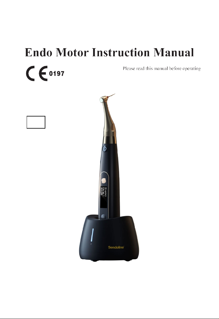
Endo Motor (mode :Ai-Motor) is mainly used in Endodontic
treatment. It is a cordless endo motor with root canal measurement
capability. It can be used as an endo motor for preparation and
enlargement of root canals, or device for measuring canal length. It can
be used to enlarge the canals while monitoring the position of the file tip
inside the canal.
Features:
a) Efficient brushless motor, low noise, long service life.
b) Cordless portable endo motor with combined length determination.
c) 360 degrees rotation of contra angle.
d) Adopt real-time feedback technology and dynamic torque control,
effectively preventing file separation.
1.3 Model and specification
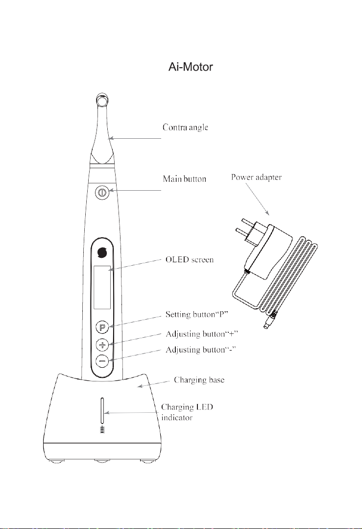
Ai-Motor
1.4 Performance and composition
The device is composed of charging base, motor handpiece, contra
angle, measuring wire, lip hook, file clip, power adapter, protectivesilicon
cover, etc.
2

3
1.5 Indications for Use
Endo Motor, Ai-Motor is cordless endodontic treatment motorized
handpiece with root canal measurement capability. It can be used for
preparation and enlargement of root canals, or measuring the canal length.
And it can be used to enlarge the canals while monitoring the position
of the file tip inside the canal.
1.6 Scope of application
The device must be operated in hospital and clinic by the qualified
dentists.
1.7 Caution
Federal law restricts this device to sale by or on the order of a
dentists.
1.8 Contraindication
a) The doctor with a pacemaker is disabled.
b) Do not use on patients with cardiac pacemakers.
c) Hemophilia patients are banned.
d) Use with caution in patients with heart disease, pregnant women
and young children.
1.9 Warnings
1.9.1 Please carefully read this Instruction Manual before first
operation.
1.9.2 This device should be operated by professional and qualified
dentist in qualified hospital or clinic.
1.9.3 Do not directly or indirectly place this device near heat source.
Operate and store this device in reliable environment.
1.9.4 This device requires special precautions regarding
electromagnetic compatibility (EMC) and must be in strict accordance
with the EMC information for installation and use. Do not use this
equipment especially in the vicinity of fluorescent lamps, radio
transmitting devices, remote control devices, handheld and mobile high-
frequency communication devices.
1.9.5 Please use the original contra angle. Otherwise it will not be used
or cause adverse consequences.
1.9.6 Please do not make any changes to the device. Any changes may
violate safety regulations, causing harm to the patient.

4
1.9.7 Please use original power adapter. Other power adapter will
result in damage to lithium battery and control circuit.
1.9.8 The motor handpiece cannot be autoclaved. Use disinfectant of
neutral pH value or ethyl alcohol to wipe its surface.
1.9.9 Before the contra angle stopping rotating, do not press the push
cover of contra angle. Otherwise the contra angle will be broken.
1.9.10 Before the motor handpiece stopping rotating, do not remove
the contra angle. Otherwise the contra angle and the gear inside motor
handpiece will be broken.
1.9.11 Please confirm whether the file is well installed and locked
before starting the motor handpiece.
1.9.12 Please set torque and speed as per the recommended
specifications of file manufacturer.
1.9.13 Error in replacing lithium batteries can lead to unacceptable
risks, so use the original lithium battery and replace the lithium battery
according to the correct steps in the instructions.
1.9.14 Please remove the battery if the motor handpiece is not likely
to be used for some time.
1.9.15 Charging the wireless handpiece will generate heat, and the
surface temperature of charging base and motor handpiece will rise. It is
recommended that the time of contacting motor handpiece and charging
base during wireless charging should not exceed 10 seconds (only for Ai-
Motor).
1.10 Device safety classification
1.10.1 Type of operation mode: Continuous operating device
1.10.2 Type of protection against electric shock: Class II equipment
with internal power supply
1.10.3 Degree of protection against electric shock: B type applied
part
1.10.4 Degree of protection against harmful ingress of water:
Ordinary equipment (IPX0)
1.10.5 Degree of safety application in the presence of a flammable
anesthetic mixture with air, oxygen, or nitrous oxide: Equipment cannot
be used in the presence of a flammable anesthetic mixture with air,
oxygen, or nitrous oxide.
1.10.6 Applied part: contra angle, lip hook, file clip, touch probe.
1.10.7 The contact duration of applied part: 1 to 10 minutes.
1.10.8 The temperature of the surface of applied part may reach
46.6℃.
5
1.11 Primary technical specifications
1.11.1 Battery
Lithium battery in motor handpiece: 3.7V /2000mAh
1.11.2 Power adapter (Model: ADS-6AM-06N 05050/UE08WCP-
050100SPA)
Input: ~100V-240V 50Hz/60Hz 0.4A Max
Output: 5.0V 1A
1.11.3 Torque rang: 0.4Ncm-5.0Ncm(4mNm ~ 50mNm)
1.11.4 Speed rang: 100rpm~1800rpm
1.11.5Wireless charging (only for Ai-Motor)
Frequency range: 112-205KHz
Maximum RF output power of the product: 9.46dBuA/m@3m
1.12 Environment parameters
1.12.1 Environment temperature: +5℃ ~ +40℃
1.12.2 Relative humidity: 30% ~ 75%
1.12.3 Atmospheric pressure: 70kPa ~ 106kPa
2Installation
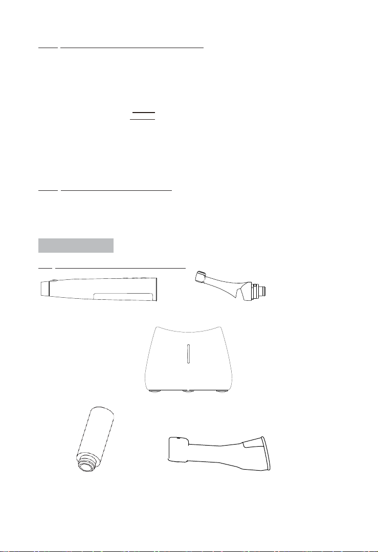
2.1 Basic accessories of product
Motor handpiece Contra angle
Ai-Motor Charging base
Nozzle Protective silicon cover
6
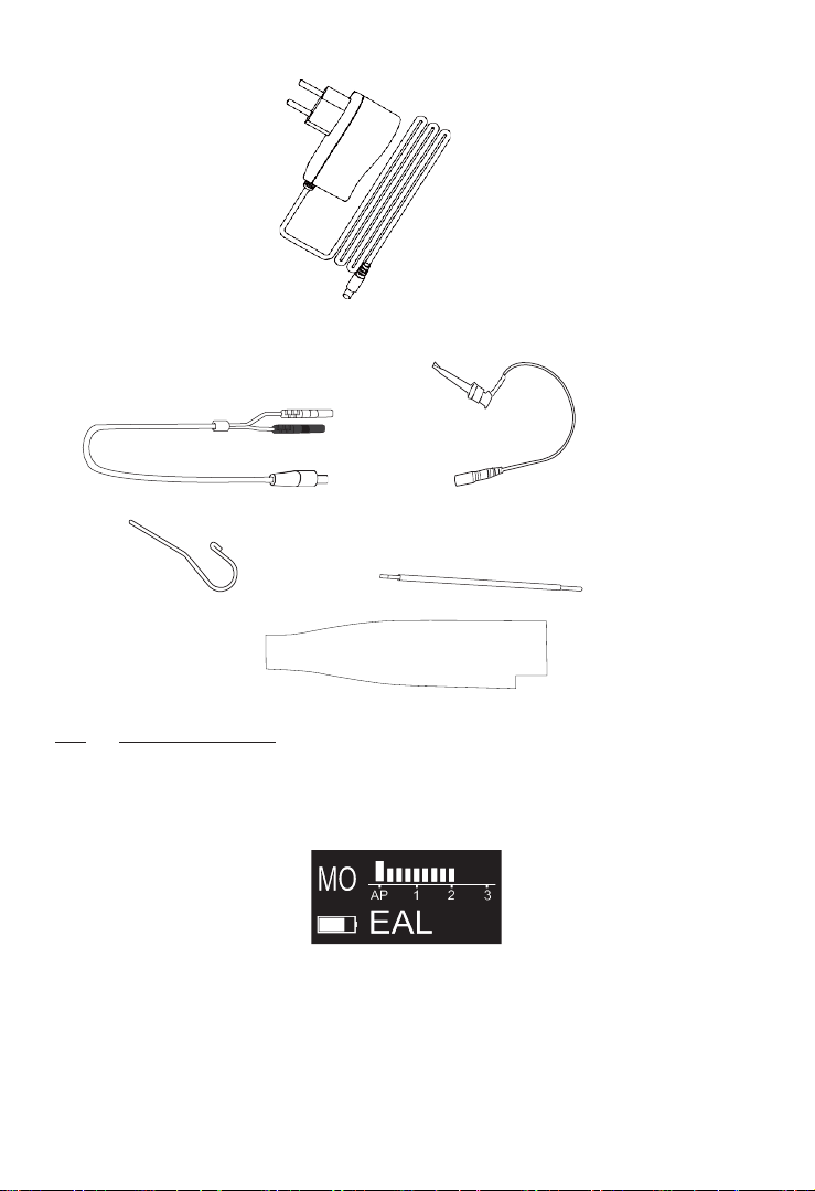
Power adapter
Measuring wire File clip
Lip hook Touch probe
Disposable insulation sleeves
2.2 Display Screens
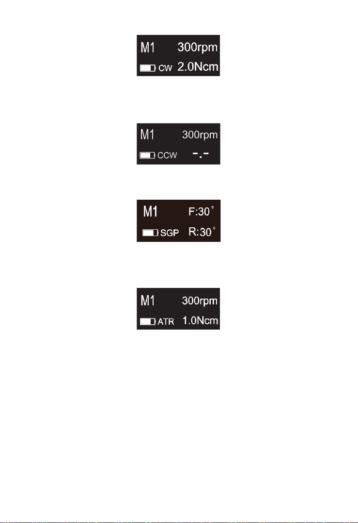
2.2.1 Display Screens for 6 Operation Modes and Standby
2.2.1.1 EAL Mode
This mode is for canal measurement. The motor handpiece does not
run in this mode.
2.2.1.2 CW Mode
The motor handpiece rotates forward 360º, clockwise direction.
7
2.2.1.3 CCW Mode
The motor handpiece rotates counterclockwise direction only. This
mode is used to inject calcium hydroxide and other medicant. When this
mode is being used, a double-beep sounds continuously.
2.2.1.4 SGP Mode
Safety Glide Path Mode
F: Forward angle, R: Reverse angle
The rotation angle is adjustable, but the forward angle must be equal
to the reverse angle.
2.2.1.5 ATR Mode
ATR: Adaptive Torque Reverse function.
During continuous rotation movement, when torque resistance of the
instrument is higher than the pre-set torque limit the instrument will rotate
counter clockwise
2.2.2 Torque Display
This appears when the motor is running. Meter shows the torque load
on the file.

8
2.2.3 Canal Measurement Display
This appears when a file is inside the canal and the lip hook is
contacting the patient mouth. Bars in meter show the location of the file
tip. In the EAL Mode, If the length is less than 1.0, the display will be
enlarged.
The meter numbers 1.0, 2.0, 3.0 and digital numbers 00-16 do not
represent the actual length from the apical foramen. It simply indicates the
file progression towards the apex. The digital numbers -1 and -2 indicate
that the file has passed the apex foramen. The digital number “00”indicate
that the file has reached the apex foramen. Subtract 0.5-1mm from the
measured file length as the working length. These numbers are used to
estimate the canal’s working length.
2.3 Instructions for contra angle
2.3.1 The contra angle adopts precision gear transmission, and the
transmission ratio is 6:1.
2.3.2 Before the first use and after treatments, please clean and
disinfect contra angle with disinfectant of neutral PH value. After
disinfection, lubricate it with specific cleaning oil. Finally, sterilizeit
under high temperature and high pressure (134℃, 2.0bar~2.3bar
(0.20MPa~0.23MPa)).
2.3.3 The contra angle can only be used cooperatively with thisdevice.
Otherwise the contra angle will be damaged.
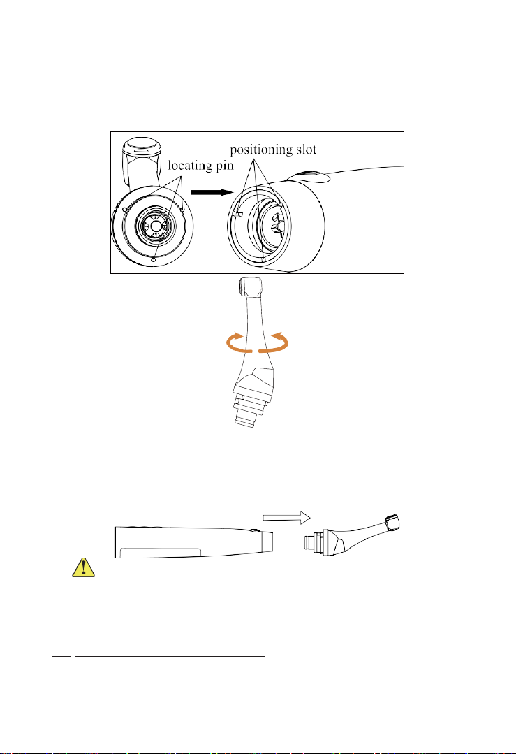
2.4 Installation and removal of contra angle.
2.4.1 Installation
9
Align any locating pin of the contra-angle with the positioning slot
on the motor handpiece and push the contra-angle horizontally. The three
locating pins on the contra-angle are inserted into those three positioning
holes on the motor handpiece. A “click” sound indicates that the
installation is in place. The contra-angle can be rotated 360° freely.
The contra-angle is free to rotate, adapting to the root canal of different
positions, and it is convenient to watch the screen when operating.
2.4.2 Removal
Pull out the contra angle horizontally when the motor handpiece does
not run.
Warnings:
a) Before plugging in or pulling out contra angle, please first stop the
motor handpiece.
b) After installation, please check and confirm that the contra angle
has been well installed.
2.5 Installation and removal of file
2.5.1 Installation of file

10
Before starting the device, plug the file into the hole of contra angle
head.
Hold down the push button on the contra angle and insert the file. Turn
the file back and forth until it is lined up with interior latch groove and
slips into place. Release the button to lock the file into the contra angle.
Warnings:
After plugging the file into contra angle, let go the hand on push
cover to assure that the file cannot be taken out.
Be careful when inserting files to avoid injury to fingers.
Inserting and removing files without holding the push button may
damage the chuck of contra angle.
Please use files with shanks meet the ISO standard. (ISO standard:
Ø2.334 – 2.350 mm)
2.5.2 Removal of file
Pressing the push cover, and then directly pull out the file.
Warnings:
Before plugging and pulling out the file, the motor handpiece must be
stopped.
Be careful when removing files to avoid injury to fingers.
Removing files without holding the push button will damage the

11
chuck of contra angle.
2.6 Canal measurement functional connection
This is not required if the canal measurement function will not be used.
Connect the measuring wire to the motor handpiece. Line up the
measuring wire plug with the notch on the back of the motor and push it
all the way in.
Connect the file clip plug into the socket (black) on the measuring
wire. Connect the lip hook to the socket (white) on the measuring wire.
Warnings:
Connect the lip hook to the socket (white) on the measuring wire.
Otherwise, the function of root canal preparation and root canal length
measurement cannot be used together.
2.7 Installation and removal of disposable insulation sleeves

12
2.7.1 Installation
Before each use of the handpiece and after the handpiece is cleaned
and disinfected,put on a disposable insulating sleeve. Take the insulating
sleeve out of the insulating sleeve box, then insert the insulating sleeve
into the motor handpiece from the thin end of the handpiece and install the
insulating sleeve until there is no obvious wrinkle.
After installing the disposable insulating sleeve, wrap the barrier film
around the handpiece surface. After that, clean and disinfect the surface of
the handpiece. Refer to Chapter 6.3 for cleaning and disinfection
procedures.
2.7.2 Removing
After each use, remove the barrier film and slowly pull the isolation
sleeve from the thin end of the handpiece.
Warming: Insulating sleeves are not reusable
3Function and operation of product
3.1 Button definition and settings
a. Turn power on
Press Main button to turn on motor handpiece.
b. Turn power off
Hold down the setting button “P”, then press Main button to turn off
motor handpiece.
c. Customized program change
Press Adjusting button “+”/“-” during standby sate.
d. Parameter setting
Press Setting button “P” till target parameters, press Adjusting button
“+”/“-” to change, then press Main button or wait 5 seconds to confirm.
e. Preset program selection
Long press Setting button “P” to entry preset program during standby
state, press Adjusting button “+”/“-” to select file system , press Setting
button “P” to entry select file number, press Adjusting button “+”/“-” to
select file number, then press Main button to confirm.
13
f. Handpiece functions setting
With the motor handpiece turned off, hold down the Setting button “P”
and press Main button to entry handpiece functions setting, press Setting
button “P” till target setting, press Adjusting button “+”/“-” to adjust, then
press Main button to confirm.
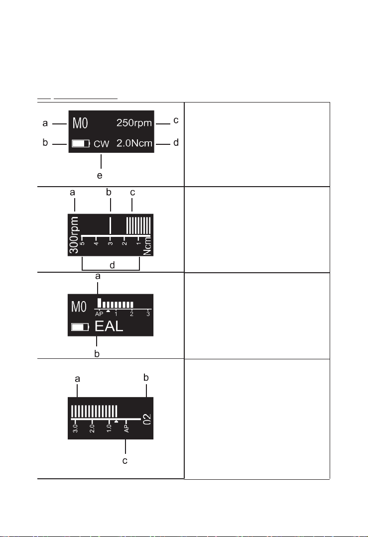
3.2 Screen display
Standby interface
a. Customized program sequence
number 0-9, totally 10 programs.
b. Battery consumption
c. Set speed
d. Set torque
e. Operation mode
Working interface
a. Set speed
b. Set torque
c. Real time torque
d. Torque display scale
Canal measurement mode interface
a. Apical reference point flash bar
b. EAL: Electronic apex locator
Canal measurement state interface
a. Canal length indicator bar
b. Indication number
Digital numbers 00-16 do not
represent the actual length from the
apical foramen. It simply indicates
the file progression towards the
apex. Number “00” indicate that the
file has reached the apical foramen.
c. Apical foramen.

14
3.3 Terms and definition
CW
Clockwise rotation, forward ration
Be applied to rotary file
CCW
Counter clockwise rotation, reverse rotation
Be applied to special file, inject calcium
hydroxide and other solutions
SGP
Safety Glide Path Mode
ATR
Adaptive torque reverse
When the torque reverse value is reduced to
normal – the motor will use a clockwise
continuous rotation movement.
Forward Angle
Angle of clockwise rotation of the file.
Reverse Angle
Angle of counter clockwise rotation of the file.
EAL
Electronic apex locator
In the mode, the device will work like a stand-
alone apex
AP
Apical foramen.
Apical Action
The file action when file tip reaches the flash bar
point.
Flash Bar Position
Shows the point inside the canal where specified
apical action is triggered.
Auto Start
The file rotation starts automatically when the file
is inserted in the canal.
Auto Stop
The file rotation stops automatically when the file
is taken out of the canal.
Apical Slow Down
The file slows down automatically as it
approaches the apex.
Activating in CW and CCW operation mode.
Apical reference point setting
interface
a. Apical reference point flash bar
b. Apical foramen
c. Digital “02” meter reading, very
near physiological apical foramen.
15
Operation Mode
5 operation modes for canal shaping and
measurement.
Such as CW, CCW, SGP, ATR and EAL.
Speed
File rotation speed.
Torque
(Torque Limit /
Trigger Torque)
For CW and CCW modes, the torque value
(Torque Limit) that triggers reverse rotation. For
ATR mode, the torque value (Trigger Torque)
that triggers ATR action.
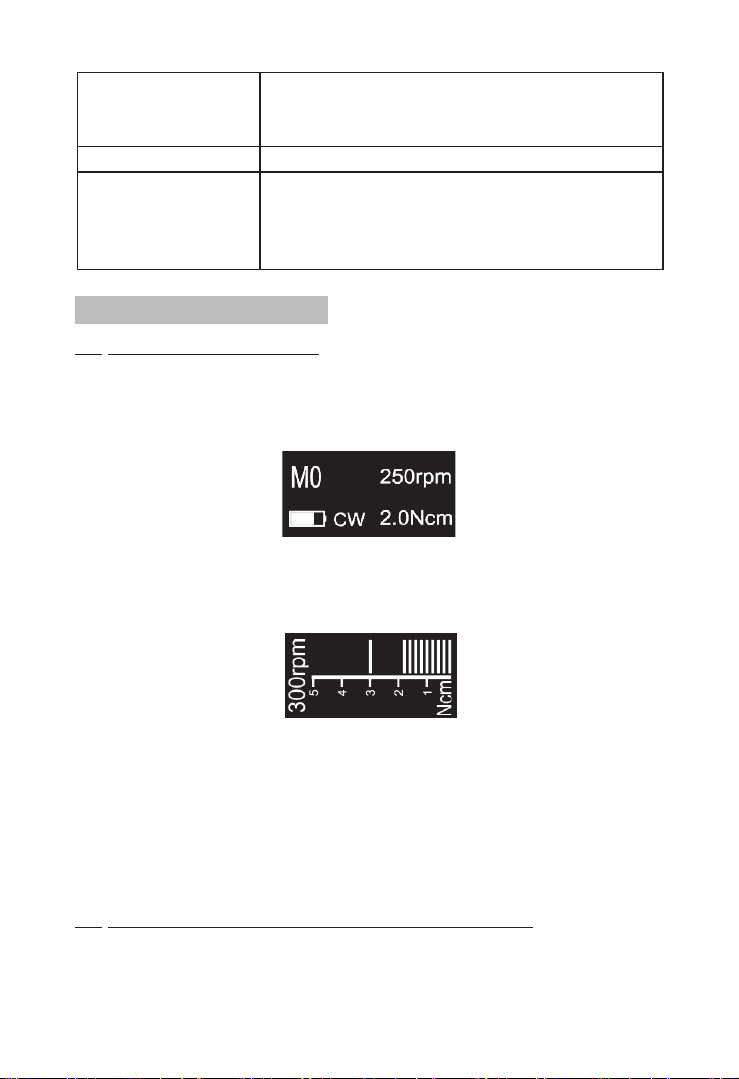
4Operation instruction
4.1 Power on and power off
4.1.1 Starting and stopping of motor handpiece
a) Under the power off state of motor handpiece, press Main button,
and then the motor handpiece will enter Standby interface. The interface
displays are as follow:
Standby interface
b) Under Standby interface, press Main button, and then the motor
handpiece will enter Working interface. The interface displays are as
follow:
Working interface
c) Press the Main button again, and then the motor handpiece backs
to Standby interface.
d) Hold down the setting button “P”, then press Main button to turn
off motor handpiece. In Standby Interface, the motor handpiece would
automatically shut down after 3 minutes without any button-pressing
operation. The motor handpiece will also automatically shut down while
it is put into the charging base.
4.2 Selecting customized program sequence number
The motor handpiece has 10 memory programs(M0-M9) and 5 preset
programs, press Adjusting button “+”/“-” to change customized program

16
sequence number during standby state.
M0-M9 is a memory program for canal shaping and measurement,
every memory program has its own parameters such as Operation mode,
speed and torque, all these parameters can be changed.

17
4.3 Parameter setting
Before starting of motor handpiece, please
check the operation mode is correct.
It has 5 operation modes for canal shaping
and measurement: CW, CCW, SGP, ATR and
EAL(See chapter 3.3 Terms and definition to get
the explanations of these modes.)
Press Setting button “P” once during standby
state, press Adjusting button “+”/“-” to select
correct Operation mode.
CCW mode is used to inject calcium hydroxide
and other medicant. When this mode is being
used, a double-beep sounds continuously,
used for indicating counter clockwise rotation
happening.
Repeatedly press Setting button “P” to check all the next level
parameters of this operation mode are expected, press Adjusting button
“+”/“-” to select if not.
The speed setting can be adjusted from 100 rpm
to 1800 rpm.
Press Adjusting button “+”/“-” to increase or
decrease speed. Long press to fast increase or
fast decrease speed.
In ATR mode, speed of 100~500rpm are
available.
In SGP mode, speed of 100~500rpm are
available.

18
The torque setting can be adjusted from 0.4Ncm
to 5.0Ncm.
Press Adjusting button “+”/“-” to increase or
decrease torque. Long press to fast increase or
fast decrease torque.
In ATR mode, the Trigger Torque of 0.4Ncm~
4.0Ncm are available.
In SGP mode, the torque of 2.0Ncm~5.0Ncm
are available.
Actions that happen automatically when the file
tip reaches the point inside the canal determined
by the Flash Bar setting.
Benefit from integration of length determination,
when the file reaches the reference point, the
motor will response according to setting, it can
be Reverse, Stop and OFF.
Press Adjusting button “+”/“-” to change.
OFF: Disable Apical Action function, file
rotating as usual even if reach the reference
point.
Stop: automatically rotation stop when reach
the reference point, upward a little bit and will
rotate again.
Reverse: automatically reverses rotation when
reach or pass the reference point, upward a
little bit, the rotation direction will change back
again.
Rotation starts automatically when the file is
inserted into the canal and the canal length
indicator bar lights up more than 2 bars.
Press Adjusting button “+”/“-” to change.
OFF: Motor does not start when file is inserted
into the canal. The Main button is used to start
and stop the motor handpiece.
ON: Motor starts automatically.
This manual suits for next models
1
Table of contents
Other Sendoline Dental Equipment manuals


Popular Dental Equipment manuals by other brands


Durr Dental
Durr Dental VS 300 S Installation and operating instructions

TPC
TPC PC2630 user manual

B.A. International
B.A. International BA-Optima BA121T Instructions for use

Woodpecker
Woodpecker UDS-K LED instruction manual

EMS
EMS AirFlow Master Operation instructions

Mikrona
Mikrona MIGMA 200-E PLANNING / MOUNTING GUIDELINES


